Note: Descriptions are shown in the official language in which they were submitted.
CA 02465821 2011-05-06
A SUNROOF WITH LEAD SCREW DRNE TLEN NT
Field of the Invention
The invention relates to a closure panel assembly for selectively covering an
opening in a motor vehicle. More particularly, the invention relates to a
closure panel
assembly including a panel that slides between a closed position and an open
position
outside the motor vehicle.
Description of Related Art
A sunroof is a popular optional accessory item for a motor vehicle. The
sunroof typically includes a closure panel that is movable relative to an
opening
formed through a roof of the motor vehicle. The closure panel is movable
between a
closed position generally flush with the roof that completely covers the
opening, and
an open position rearward of the closed position for allowing ventilation
and/or
sunlight to enter a passenger compartment of the motor vehicle. In addition,
the
closure panel is typically positionable at one of a plurality of partially
open positions
between the closed and open positions. The closure panel may be moved manually
or
via an electric motor. Various sunroofs are well-known to those skilled in the
an and
are disclosed in United States Patent Nos. 4,678,228; 4,690,453; 4,732,422;
4,893,869; 5,058,947; and 5,405,185.
There are two types of sunmafs. The first is where the closure panel is
retracted into the structure of the roof, when open, where it is hidden from
view. The
second type of sunroof; which is commonly known as a spoiler type sunroof,
includes
a lifting mechanism to raise the closure panel to a sufficient height so that
the closure
panel will clear the roof thereabove during sliding away from its closed
position. This
lifting mechanism must also account for positioning the closure panel flush
with the
surrounding roof when the closure panel is in the closed position. It is
important that
a tight seal is formed between the roof and the closure panel when the closure
panel is
in the closed position to prevent air, moisture, and noise from entering the
passenger
compartment of the motor vehicle. But maintaining the tight seal between the
closure
panel and the roof becomes more difficult over time as the multitude of parts
that
provide for lifting and sliding of the closure panel are exposed to wear and
tear. Thus,
3230677v1 l
19339/490349
CA 02465821 2004-04-30
it would be desirable to provide a mechanism that lifts and slides a closure
panel
relative to a roof of a motor vehicle, and that maintains the closure panel
flush with
the surrounding roof to provide a tight seal therebetween.
Summary of the Invention
A closure panel assembly selectively covers an opening formed in a roof of a
motor vehicle. The closure panel assembly includes a frame disposed around the
opening of the roof. The frame has a longitudinal wall including a curved
guide slot
extending between a forward end and a rearward end. A lead screw is disposed
adjacent the longitudinal wall and pivots at one end with respect thereto. A
panel is
movable relative to the lead screw for selectively covering the opening. In
addition, a
sliding bracket is secured to the panel and includes a drive nut extending
through the
guide slot to threadingly engage the lead screw. The rotation of the lead
screw allows
for movement of the drive nut to move the panel between an open position and a
closed position.
Brief Description of the Drawings
Advantages of the invention will be readily appreciated as the same becomes
better understood by reference to the following detailed description when
considered
in connection with the accompanying drawings wherein:
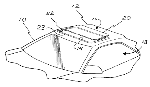
Figure 1 is a fragmentary perspective view of a motor vehicle including a
closure panel assembly according to the invention, shown in a partially open
position;
Figure 2 is a side perspective view of a panel of the closure panel assembly;
Figure 3 is a rear, fragmentary, perspective view of the panel of the closure
panel assembly with a sliding bracket having an L-shaped hinge bracket in the
foreground and a drive nut in the background;
Figure 4 is an isolated side perspective view of a frame of the closure panel
assembly including the panel thereof raised relative to the frame;
Figure 5 is rear, fragmentary, perspective view similar to Figure 3 further
including the frame and a lead screw disposed adjacent the frame;
Figure 6 is a front, fragmentary, perspective view of the panel including a
sliding bracket having a drive nut threadingly engaging the lead screw, which
is
shown isolated from the frame;
2
CA 02465821 2011-05-06
Figure 7 is an isolated, perspective view of the closure panel assembly with
the panel in the closed position and a hinge bracket in a rest position;
Figure 8 is an isolated, perspective view of the closure panel assembly with
the panel in a partially Open position in which the drive nut has moved away
from a
front and of the lead screw;
Figure 9 is an isolated, perspective view of the closure panel assembly with
the drive nut further along the lead screw;
Figure 10 is an isolated, perspective view of the closure panel assembly with
the hinge bracket in an upright position; and
Figure 11 is an isolated side perspective view of the closure panel assembly
with the panel in the open position.
Detailed Description of the Preferred embodiment
Referring to Figure 1, a motor vehicle 10 Includes a roof 12 defining an
opening 14 therethrough. A closure panel assembly, generally shown at '16,
selectively covers the opening 14 to allow sunlight and/or ventilation to
enter a
passenger compartment 18 of the motor vehicle 10. The closure panel assembly
16
includes a panel 20 that is removably securable to the roof 12 to cover the
opening 14,
and a frame 22 disposed around the opening 14 of the roof 12. A sealing member
23
extends along the frame 22 to provide a tight seal between the panel 20 and
the frame
22 when the opening 14 is completely covered by the panel 20. Although the
frame
22 in Figure I is generally rectangular-shaped, it will be appreciated that
the shape of
the frame 22 may vary depending on the configuration of the opening 14.
Further, it
is contemplated that the frame 22 may be integrally formed with the roof 12,
or that
the roof 12 may contain a plurality of openings.
Referring to Figure 2, the panel 20 includes a front edge 24, a rear edge 26.
and side edges 28, 30 extending therebetween. The panel 20 is generally
planar, and
is preferably glass and polycarbonate. It is, however, contemplated that the
panel 20
may be non-planar.
Referring to Figures 2 and 3, a pair of parallel and spaced apart sliding
brackets 32 is mounted to a bottom surface 34 of the panel 20. One of the pair
of
CA 02465821 2004-04-30
sliding brackets 32 is adjacent one of the side edges 28 while the other of
the pair of
sliding brackets 32 is adjacent the other side edge 30. Each of the pair of
sliding
brackets 32 defines a length and includes an elongated slot 36 extending along
a
portion of the length. Each of the elongated slots 36 extends between a front
end 38
and a rearward end 40 defining a travel direction for the panel 20.
Referring to Figure 3, each of the sliding brackets 32 includes a forward leg
42. The forward leg 42 extends downwardly from the sliding brackets 32. A pin
44
extends through each distal end of the forward legs 42 perpendicularly to the
sliding
brackets 32. Each pin 44 includes a head 45 and a shank 46 extending therefrom
through the forward leg 42. A drive nut 48 is secured to the shank 46 opposite
the
head 45. The drive nut 48 has a threaded through-hole 50. A spacer 52 is
mounted to
the shank 46 and is disposed along a portion thereof between the forward leg
42 and
the drive nut 48.
The closure panel assembly 16 also includes L-shaped hinge brackets 54 that
extend between the sliding brackets 32 and the frame 22. The L-shaped hinge
brackets 54 include a first leg 56. A first pin 60 extends out of the first
leg 56 and
through the elongated slot 36 of the sliding bracket 32. In the embodiment
shown, the
first leg 56 defines a channel 57 across which the first pin 60 extends. A
forward end
59 of the channel 57 defines an upper lip 61, over which the sliding bracket
32 passes
to allow the panel 20 to move from its closed position to its open position.
In
addition, a portion of the sliding bracket 32 extends into the channel 57
allowing for a
more compact, low profile when the panel 20 is in its open position.
Each of the L-shaped hinge brackets 54 also includes a second leg 58, which
extends out from the first leg 56 substantially perpendicularly thereto. A
second pin
62 extends out from a distal end 63 of the second leg 58. The second pin 62
extends
through the frame 22. The second pin 62 defines a pivot point about which the
L-
shaped hinge bracket 54 pivots. The channel 57 continues from the first leg 56
down
through the second leg 58.
The L-shaped hinge bracket 54 pivots between a retracted position, shown in
4
CA 02465821 2004-04-30
Figure 7, and an upright position, shown in Figures 10 and 11. When the L-
shaped
hinge bracket 54 is in the retracted position, the panel 20 is in a closed
position.
When the L-shaped hinge bracket 54 is in the upright position, the panel 20 is
raised
above the roof 12 to provide clearance for the panel 20 as the panel 20 slides
relative
to the frame 22 into and out of an open position.
Referring once again to Figure 3, a wheel 64 is positioned within the portion
of the channel 57 extending through the second leg 58. The wheel 64 is moved
into a
camming relationship with the sliding bracket 32 when the L-shaped hinge
bracket 54
is pivoted to the upright position. The wheel 64 urges the sliding bracket 32
over the
upper lip 61. The sliding bracket 32 also slides over the wheel 64 relative to
the first
pin 60, as the panel 20 moves to its open position when the L-shaped hinge
bracket 54
is in the upright position. Thus, the motion of the first pin 60 with respect
to the
elongated slot 36 is achieved as a function of the position of the hinge
bracket 54.
Referring to Figure 4, the frame 22 includes a forward wall 66, a rearward
wall 68, and opposing longitudinal walls 70, 72 extending therebetween. The
longitudinal walls 70, 72 each include a guide slot 74 extending through a
curved path
between a forward end 76 and a rearward end 78. In the embodiment shown, much
of
the curve in the path is disposed adjacent the forward end 76. The forward end
76 is
positioned along each of the longitudinal walls 70, 72 at a height different
from that of
the rearward end 78. In a preferred embodiment, the guide slot 74 extends at
an angle
with respect to the frame 22 such that is rises as it extends from the forward
end 76 to
the rearward end 78.
The invention described to this point defines kinematics of the closure panel
assembly 16, and a drive for moving the panel 20 between the open and closed
positions may be manually operated or power activated.
For power operation, the drive includes a rotatable lead screw 80 disposed
adjacent the longitudinal wall 72. The lead screw 80 extends between a first
end 82
and a second end 84. Although reference is being made only to one of the
longitudinal walls 72, it will be appreciated that the following applies
equally to the
CA 02465821 2004-04-30
other longitudinal wall 70. The lead screw 80 defines a length generally equal
to that
of the guide slot 74.
Referring to Figures 5 and 6, the drive nut 48 threadedly engages the lead
screw 80. More specifically, the lead screw 80 extends through the threaded
through-
hole 50 of the drive nut 48 so that rotation of the lead screw 80 will cause
the drive
nut 48 to move therealong between the first 82 and second 84 ends, which will
drive
the panel 20 between the closed and open positions. At the same time that the
drive
nut 48 moves along the lead screw 80, the spacer 52 slides within the guide
slot 74
between the forward 76 and rearward 78 ends.
The lead screw 80 is retained adjacent to the longitudinal wall 72 by a
mounting bracket 86. A rear end 97 of the mounting bracket 86 is pivotally
secured
along an outboard surface 88 of the longitudinal wall 72. The mounting bracket
86
includes front 90 and rear 92 openings for receiving the lead screw 80. The
lead
screw 80 is fixedly secured to the mounting bracket 86 such that as the
mounting
bracket 86 pivots, the lead screw 80 moves with the mounting bracket 86.
Therefore,
when the panel 20 moves to its closed position, and the spacer 52 is moving
through
the curved path towards the forward end 76 of the guide slot 74, the mounting
bracket
86 pivots so that a front end 95 thereof as well as the first end 82 of the
lead screw 80
drop downwards. As a result, the panel 20 is brought into tight, sealing
engagement
with the frame 22. When the panel 20 moves to its open position, the mounting
bracket 86 pivots so that the front end 95 thereof, and with it the first end
82 of the
lead screw 80, is urged upwards. Thus, the movement of the drive nut 48 along
the
lead screw 80 approximates the movement of the spacer 52 through the curved
path of
the guide slot 74. The lead screw 80 cooperates with the L-shaped hinge
bracket 54
in the initial raising of the panel 20 above to the frame 22.
A reversible motor 94 is mounted along the mounting bracket 86 and is
operatively connected to the lead screw 80. Preferably, a single motor drives
a pair of
flexible cables that are operably connected to an end of the lead screw 80
effecting
rotation thereof. Upon activation, the motor 94 will rotate the lead screw 80
in either
a clockwise or counterclockwise direction.
6
CA 02465821 2004-04-30
The operation of the closure panel assembly 16 will now be described with
reference to Figures 7 through 11. Referring first to Figure 7, when the panel
20 is in
the closed position, the drive nut 48 is positioned at the first end 82 of the
lead screw
80, which abuts the lower end 95 of the front opening 90. In addition, the
spacer 52 is
located at the forward end 76 of the guide slot 74, the first pin 60 abuts the
rearward
end 40 of the elongated slot 36, and the L-shaped hinge bracket 54 is in its
retracted
position.
Referring to Figure 8, the drive nut 48 moves towards the second end 84 of the
lead screw 80 upon rotation thereof, thus moving the panel 20 out of its
closed
position. As the panel 20 moves out of its closed position, the spacer 52
moves out of
the forward end 76 of the guide slot 74 through the curved path thereof. At
the same
time, the first end 82 of the lead screw 80 is raised to abut the upper end 95
of the
front opening 90. The panel 20 moves initially through the curved path of the
forward
end 76 of the guide slot 74 and is raised above the frame 22. The rearward
movement
of the panel 20 drives the L-shaped hinge bracket 54 to pivot out of its
retracted
position (since at this point the sliding bracket 32 engages the upper lip 61
of the L-
shaped hinge bracket 54). Specifically, the L-shaped hinge bracket 54 pivots
about
the second pin 62 relative to the frame 22.
Referring to Figure 9, the drive nut 48 continues to move along the lead screw
80 towards the second end 84 thereof, thus further moving the panel 20 to its
open
position. In addition, the L-shaped hinge bracket 54 continues to rotate
towards its
upright position, further raising the panel 20 relative to the frame 22.
Referring to Figure 10, the L-shaped hinge bracket 54 is in its upright
position.
At this time, the wheel 64 disposed within the channel 65 engages the sliding
bracket
32 and urges it over the upper lip 61 of the L-shaped hinge bracket 54. Rotary
movement of the panel 20 is now complete and from this point on, the panel 20
will
only slide rearward towards the open position, shown in Figure 11. The sliding
bracket 32 slides relative to the first pin 60 until it abuts the front end 38
of the
elongated slot 36. At the same time that the first pin 60 contacts the front
end 38 of
7
CA 02465821 2004-04-30
the elongated slot 36, the drive nut 48 moves to the second end 84 of the lead
screw
80 and the spacer 52 moves to the rearward end 78 of the guide slot 74 so that
the
panel 20 is in its open position.
It will be appreciated that although the closure panel assembly 16 is shown
with regard to a panel and an opening of a roof, the closure panel assembly 16
may
also be utilized with various other panels including, but not limited to,
vertical and
horizontal sliding doors, decklids, glass panels, sun visors, and vertical
gates. Certain
other advantages of this invention may be appreciated including a panel
inherently
secured closed by its four corners, a downward motion of the panel at full
closure to
assist in positive compression of a seal, and a simple, more easily powered
mechanism that achieves a tilt and slide motion for a panel.
The invention has been described in an illustrative manner. It is to be
understood that the terminology, which has been used, is intended to be in the
nature
of words of description rather than of limitation. Many modifications and
variations
of the invention are possible in light of the above teachings and thus the
invention
may be practiced other than as specifically described.
8