Note: Descriptions are shown in the official language in which they were submitted.
CA 02465933 2004-04-30
3105 0068
METHODS AND APPARATUS FOR REFORMING
AND EXPANDING TUBULARS IN A WELLBORE
BACKGROUND OF THE INVENTION
Field of the Invention
The present invention generally relates to methods and apparatus for
expanding a tubular body in a wellbore. More specifically, the invention
relates to
methods and apparatus for forming a cased wellbore having an inner diameter
that
does not decrease with increasing depth within a formation.
Description of the Related Art
In well completion operations, a wellbore is formed to access hydrocarbon-
bearing formations by the use of drilling. Drilling is accomplished by
utilizing a drill
bit that is mounted on the end of a drill support member, commonly known as a
drill
string. To drill within the wellbore to a predetermined depth, the drill
string is often
rotated by a top drive or rotary table on a surface platform or rig, or by a
downhole
motor mounted towards the lower end of the drill string. After drilling to a
predetermined depth, the drill string and drill bit are removed and a section
of casing
is lowered into the wellbore. An annular area is thus formed between the
string of
casing and the formation. The casing string is temporarily hung from the
surface of
the well. A cementing operation is then conducted in order to fill the annular
area
with cement. Using apparatus known in the art, the casing string is cemented
into
the wellbore by circulating cement into the annular area defined between the
outer
wall of the casing and the borehole. The combination of cement and casing
strengthens the wellbore and facilitates the isolation of certain areas of the
formation
behind the casing for the production of hydrocarbons.
It is common to employ more than one string of casing in a wellbore. In this
respect, the well is drilled to a first designated depth with a drill bit on a
drill string.
The drill string is removed. A first string of casing or conductor pipe is
then run into
the wellbore and set in the drilled out portion of the welibore, and cement is
circulated into the annulus behind the casing string. Next, the well is
drilled to a
second designated depth, and a second string of casing, or liner, is run into
the
drilled out portion of the wellbore. The second string is set at a depth such
that the
upper portion of the second string of casing overlaps the lower portion of the
first
1
_,.
CA 02465933 2004-04-30
3105 0068
string of casing. The second liner string is then fixed, or "hung" off of the
existing
casing by the use of slips which utilize slip members and cones to wedgingly
fix the
new string of liner in the wellbore. The second casing string is then
cemented. This
process is typically repeated with additional casing strings until the well
has been
drilled to total depth. As more casing strings are set in the wellbore, the
casing
strings become progressively smaller in diameter in order to fit within the
previous
casing string. In this manner, wells are typically formed with two or more
strings of
casing of an ever-decreasing diameter.
Decreasing the diameter of the wellbore produces undesirable consequences.
Progressively decreasing the diameter of the casing strings with increasing
depth
within the wellbore limits the size of wellbore tools which are capable of
being run
into the wellbore. Furthermore, restricting the inner diameter of the casing
strings
limits the volume of hydrocarbon production which may flow to the surface from
the
formation.
Recently, methods and apparatus for expanding the diameter of casing
strings within a wellbore have become feasible. As a result of expandable
technology, the inner diameter of the cased wellbore does not decrease as
sharply
upon setting more casing strings within the wellbore as the inner diameter of
the
cased wellbore decreases when not using expandable technology. When using
expandable casing strings to line a wellbore, the well is drilled to a first
designated
depth with a drill bit on a drill string, then the drill string is removed. A
first string of
casing is set in the drilled out portion of the wellbore, and cement is
circulated into
the annulus behind the casing string. Next, the well is drilled to a second
designated
depth, and a second string of casing is run into the drilled out portion of
the wellbore
at a depth such that the upper portion of the second string of casing overlaps
the
lower portion of the first string of casing. The second casing string is then
expanded
into contact with the existing first string of casing with an expander tool.
The second
casing string is then cemented. This process is typically repeated with
additional
casing strings until the well has been drilled to total depth.
An exemplary expander tool utilized to expand the second casing string into
the first casing string is fluid powered and run into the wellbore on a
working string.
The hydrauiic expander tool includes radially expandable members which,
through
2
CA 02465933 2004-04-30
3105 0068
fluid pressure, are urged outward radially from the body of the expander tool
and into
contact with the second casing string therearound. As sufficient pressure is
generated on a piston surface behind these expansion members, the second
casing
string being acted upon by the expansion tool is expanded past its point of
elastic
deformation. In this manner, the inner and outer diameter of the expandable
tubular
is increased in the wellbore. By rotating the expander tool in the wellbore
and/or
moving the expander tool axially in the wellbore with the expansion member
actuated, a tubular can be expanded into plastic deformation along a
predetermined
length in a wellbore.
The method of expanding the second casing string into the first casing string
involves expansion of the second casing string past its elastic limit once
located at
the desired depth within the wellbore. Because a casing string is typically
only
capable of expansion to about 22-25% past its elastic limit, the amount of
expansion
of the casing string is limited when using this method. Expansion past about
22-25%
of its original diameter may cause the casing string to fracture due to
stress.
The advantage gained with using expander tools to expand expandable
casing strings is the decreased annular space between the overlapping casing
strings. Because the subsequent casing string is expanded into contact with
the
previous string of casing, the decrease in diameter of the wellbore is
essentially the
thickness of the subsequent casing string. However, even when using expandable
technology, casing strings must still become progressively smaller in diameter
in
order to fit within the previous casing string.
Currently, monobore wells are being investigated to further limit the decrease
in the inner diameter of the wellbore with increasing depth. Monobore wells
would
theoretically result when the wellbore is approximately the same diameter
along its
length, causing the path for fluid between the surface and the wellbore to
remain
consistent along the length of the wellbore and regardless of the depth of the
well.
With a monobore well, tools could be more easily run into the wellbore because
the
size of the tools which may travel through the wellbore would not be limited
to the
constricted inner diameter of casing strings of decreasing inner diameters.
Theoretically, in the formation of a monobore well, a first casing string
could be
inserted into the wellbore. Thereafter, a second casing string of a smaller
diameter
3
CA 02465933 2004-04-30
3105 0068
than the first casing string could be inserted into the wellbore and expanded
to
approximately the same inner diameter as the first casing string.
Certain problems have arisen during the investigation of monobore wells.
One problem relates to the expansion of the smaller casing string into the
larger
casing string to form a sealed connection therebetween where the first and
second
casing strings overlap. Forming a monobore well would involve first running
the
smaller casing string through the restricted inner diameter of the wellbore
produced
by the larger casing string, then expanding the smaller casing string to an
inner
diameter at least as large the smallest inner diameter of the larger casing
string.
This portion of the expansion of the smaller casing string likely would
increase the
inner diameter of the smaller casing string by the limit of 22-25%. To insert
an even
smaller casing string inside the smaller casing string to form a monobore
well, the
inner diameter of a lower portion of the smaller casing string would have to
be
enlarged to receive the even smaller casing string. In this way, expansion of
the
casing string to over 25% of its original diameter would be necessary, but not
currently possible. Merely expanding the casing string past its elastic limit
after
passing the restricted inner diameter portion may not allow the casing string
to
expand to a large enough inner diameter to form a substantially monobore well,
as
the percentage which the casing string may expand past its elastic limit is
limited by
structural constraints of the casing string. Attempts to expand the casing
string
further than about 22-25% past its elastic limit may cause the casing string
to
fracture or may simply be impossible.
Another type of expansion is currently performed in the context of casing
patches. A casing patch is a tubular body which is expanded into contact with
the
wellbore or casing within the wellbore to patch leaking paths existing in the
wellbore
or cased welibore. To patch the leaking path within the casing or wellbore, a
casing
patch is often deformed so that the casing patch possesses a smaller inner
diameter
than the inner diameter of the existing casing or wellbore, then the casing
patch is
reformed to a larger inner diameter when the casing patch is located at the
desired
location for reformation of the casing patch. The reforming process is often
performed by an expander cone. This method often leaves stress lines in the
reformed casing patch where the corrugations originally existed, weakening the
4
CA 02465933 2004-04-30
3105 0068
casing patch at the stress lines so that the casing patch is susceptible to
leaking
wellbore fluids into the casing patch due to the pressure exerted by wellbore
fluids.
Utilizing the current methods of expanding a casing string or reforming a
casing patch, the problems described above are evident when a casing string or
casing patch must run through a restriction in the inner diameter of the
wellbore,
such as a restriction formed by a packer or a previously installed casing
patch, and
then expand to an inner diameter at least as large as the restriction once the
casing
string or casing patch is lowered below the restriction. When using a casing
patch,
merely reforming the casing patch may leave stress lines in the casing patch
which
may allow fluid leakage therethrough. When using a casing string, merely
expanding
the casing string past its elastic limit by 22-25% may not allow enough
expansion to
increase the inner diameter of the casing string to at least the inner
diameter of the
restriction.
There is, therefore, a need for a method for enlarging the inner diameter of a
casing string or other tubular body by more than current methods allow without
compromising the structural integrity of the casing string or tubular body.
There is a
further need for a method for expanding the inner diameter of a casing string
or
tubular body by a larger percentage than the percentage expansion allowed past
the
elastic limit after running the casing string or tubular body through a
restricted inner
diameter portion of the wellbore. There is yet a further need for a method of
expanding a lower portion of the inner diameter of a casing string or tubular
body
further than the remaining portions of the casing string or tubular body
without
compromising the structural integrity of the lower portion of the casing
string or
tubular body.
SUMMARY OF THE INVENTION
The present invention generally includes a method of expanding at least a
portion of a tubular body within a wellbore comprising running a deformed
tubular
body into the wellbore, reforming the tubular body, and expanding at least the
portion
of the tubular body. The deformed tubular body may include corrugations
inflicted
upon the tubular body before insertion of the tubular body into the wellbore.
Expanding the tubular body may comprise expanding the tubular body past its
elastic
limit.
5
CA 02465933 2004-04-30
3105 0068
In one aspect, a method of forming a substantially monobore well is disclosed,
comprising running a deformed first casing string into a wellbore, reforming
the first
casing string, and expanding a lower portion of the first casing string past
its elastic
limit. The method may further comprise running a second deformed casing string
into the wellbore to a depth at which the lower portion of the first casing
string
overlaps an upper portion of the second casing string, and reforming the
second
casing string. The lower portion of the second casing string may then be
expanded
past its elastic limit.
In yet another aspect, the present invention includes a method of forming a
cased wellbore, comprising deforming a tubular body so that at least a portion
of the
deformed tubular body has a smaller inner diameter than an inner diameter of
the
tubular body, running the deformed tubular body into a wellbore through a
restricted
inner diameter portion, locating the deformed tubular body below the
restricted inner
diameter portion, reforming the tubular body, and expanding at least a portion
of the
tubular body past its elastic limit.
The present invention advantageously provides a method for enlarging the
inner diameter of a casing string by more than about 22-25% without
compromising
the structural integrity of the casing string. Further, the present invention
provides a
method for expanding the inner diameter of a casing string further than the
allowed
elastic limit after running the casing string through a restricted inner
diameter portion
of the wellbore. The present invention also allows a method of expanding a
lower
portion of the inner diameter of a casing string further than the remaining
portions of
the casing string without compromising the structural integrity of the lower
portion of
the casing string.
BRIEF DESCRIPTION OF THE DRAWINGS
So that the manner in which the above recited features of the present
invention operate can be understood in detail, a more particular description
of the
invention, briefly summarized above, may be had by reference to embodiments,
some of which are illustrated in the appended drawings. It is to be noted,
however,
that the appended drawings only illustrate typical embodiments of this
invention and
6
CA 02465933 2004-04-30
3105 0068
are therefore not to be considered limiting of its scope, for the invention
may admit to
other equally effective embodiments.
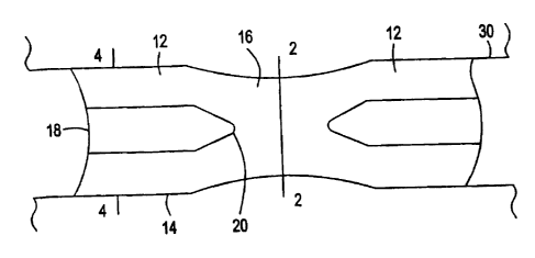
Figure 1 is a schematic view of a section of deformable downhole tubing in
accordance with an embodiment of the present invention.
Figure 2 is a sectional view on line 2 - 2 of Figure 1.
Figure 3 is a sectional view corresponding to Figure 2, showing the tubing
following expansion.
Figure 4 is a sectional view on line 4- 4 of Figure 1.
Figure 5 is a schematic view of a step in the installation of a tubing string
in
accordance with an embodiment of the present invention.
Figure 6 is a cross-sectional view of a lower portion of a corrugated casing
string with an expander tool disposed at the lower portion of the casing
string.
Figure 7 is a cross-sectional view of the corrugated casing string with a
portion of the expander tool of Figure 6 attached. The assembly is run into an
open
hole portion of a cased wellbore.
Figure 8 is a downward view of the corrugated casing string of Figure 7
disposed within the wellbore.
Figure 9 is a sectional view of the corrugated casing string of Figure 7.
Figure 10 is a cross-sectional view of the corrugated casing string being
reformed by the expander tool, showing a portion of the expander tool.
Figure 11 is a cross-sectional view of the reformed casing string. An upper
portion of the casing string is reformed into contact with a lower portion of
the casing
previously disposed within the wellbore.
Figure 12 is a downward view of the reformed casing string of Figure 10
disposed within the wellbore.
7
CA 02465933 2004-04-30
3105 0068
Figure 13 is a cross-sectional view of the reformed casing string disposed
within the wellbore. A lower portion of the reformed casing string is shown
expanded
past its elastic limit by a compliant expander tool.
Figure 14 is a cross-sectional view of the reformed and expanded casing
string cemented into the wellbore.
Figure 15 is a cross-sectional view of an alternate embodiment of the present
invention in the run-in configuration. A system which may be used to reform a
corrugated casing string in one run-in of expander tools is shown disposed in
a
partially cased wellbore. The system includes expander tools connected to one
another and releasably attached to the corrugated casing string.
Figure 16 is a cross-sectional view of Figure 15 in a partially cased
wellbore,
wherein the system is reforming the corrugated casing string and expanding a
lower
portion of the casing string in the same run-in of the expander tools.
Figure 17 is a cross-sectional view of an expander tool with a deformed
casing string attached thereto within a wellbore in the run-in position.
Figure 18 is a cross-sectional view of the expander tool of Figure 17
reforming
and expanding the casing string past its elastic limit.
Figure 19 is a sectional view of the casing string of Figures 1-19, showing
the
casing string partially expanded.
Figure 20 is a sectional view of an expander tool used to expand the casing
string of Figure 19.
Figure 21 is a graph of diameters of the casing string of Figure 19 and of the
expander tool of Figure 20 versus the radius of curvature between the
expansion
surface and the release surface of the expander tool of Figure 20.
DETAILED DESCRIPTION OF THE PREFERRED EMBODIMENT
It is among the objectives of embodiments of the present invention to
facilitate
use of folded tubing in downhole applications, and in particular to permit use
of
8
CA 02465933 2004-04-30
3105 0068
tubing made up from a plurality of folded pipe sections which may be coupled
to one
another at surface before being run into the bore.
According to a first aspect of the present invention there is provided
downhole
apparatus comprising a plurality of tubing sections, each tubing section
having
substantially cylindrical end portions initially of a first diameter for
coupling to end
portions of adjacent tubing sections and being expandable at least to a larger
second
diameter, and intermediate folded wall portions initially in a folded
configuration and
being unfoldable to define a substantially cylindrical form at least of a
larger third
diameter.
The invention also relates to a method of lining a bore using such apparatus.
Thus, the individual tubing sections may be coupled together via the end
portions to
form a string to be run into a bore. The tubing string is then reconfigured to
assume
a larger diameter configuration by a combination of mechanisms, that is at
least by
unfolding the intermediate portions and expanding the end portions. The
invention
thus combines many of the advantages available from folded tubing while also
taking
advantage of the relative ease of coupling cylindrical tubing sections;
previously,
folded tubing has only been proposed as continuous reelable lengths, due to
the
difficulties that would be involved in coupling folded tubing sections.
Preferably, transition portions are be provided between the end portions and
the intermediate portions, and these portions will be deformable by a
combination of
both unfolding and expansion. The intermediate wall portion, transition
portions and
end portions may be formed from a single piece of material, for example from a
single extrusion or a single formed and welded sheet, or may be provided as
two or
more parts which are assembled. The different parts may be of different
materials or
have different properties. The end portions may be foldable, and may have been
previously folded. Alternatively, or in addition, the end portions may be
folded
following coupling or making up with other end portions. This would allow
cylindrical
tubing sections to be made up on site, and then lowered into a well through a
set of
rollers which folded the tubulars including the end portions, into an
appropriate,
smalier diameter folded configuration. Indeed, in certain aspects of the
invention the
end portion may only be subject to unfolding, and may not experience any
expansion.
9
CA 02465933 2004-04-30
3105 0068
The end portions may be provided with means for coupling adjacent tubing
sections. The coupling means may be in the form of male or female threads
which
allow the tubing sections to be threaded together. Alternatively, or in
addition, the
coupling means may comprise adhesive or fasteners, such as pins, bolts or
dogs, or
may provide for a push or interference type coupling. Other coupling means may
be
adapted to permit tubing section to be joined by welding or by amorphous
bonding.
Alternatively, or in addition, the apparatus may further comprise expandable
tubular
connectors. In one embodiment, an expandable connector may define female
threads for engaging male threaded end portions of the tubing sections.
Preferably, the first diameter is smaller than the third diameter. The second
and third diameters may be similar. Alternatively, the unfolded intermediate
wall
portions may be expandable from the third diameter to a larger fourth
diameter,
which fourth diameter may be similar to the second diameter.
According to another aspect of the present invention there is provided a
method of creating a bore liner, the method comprising providing a tubing
section
having a folded wall and describing a folded diameter; running the tubing
section into
a bore; unfolding the wall of the tubing section to define a larger unfolded
diameter;
and expanding the unfolded wall of the tubing section to a still larger
diameter. This
unfolding and expansion of the tubing section is useful in achieving
relatively large
expansion ratios which are difficult to achieve using conventional mechanisms,
and
also minimising the expansion forces necessary to achieve desired expansion
ratios.
The unfolding and expansion steps may be executed separately, or may be
carried out in concert. One or both of the unfolding and expansion steps may
be
achieved by passing an appropriately shaped mandrel or cone through the
tubing, by
applying internal pressure to the tubing, or preferably by rolling expansion
utilising a
rotating body carrying one or more rolling members, most preferably a first
set of
rolling members being arranged in a conical form or having a tapered form to
achieve the initial unfolding, and a further set of rolling members arranged
to be
urged radially outwardly into contact with the unfolded tubing section wall.
Of
course, the number and configuration of the rolling member sets may be
selected to
suit particular applications or configurations. The initial deformation or
unfolding may
be achieved by simple bending of the tubing wall, and subsequent expansion by
CA 02465933 2004-04-30
3105 0068
radial deformation of the wall, reducing the wall thickness and thus
increasing the
wall diameter.
The tubing section may be reelable, but is preferably formed of jointed pipe,
that is from a plurality of shorter individual pipe sections which are
connected at
surface to make up a tubing string. Alternatively, the tubing section may be
in the
form of a single pipe section to be used as, for example, a straddle.
Preferably, an upper portion of the tubing section is deformed initially, into
contact with a surrounding wall, to create a hanger and to fix the tubing
section in the
bore. Most preferably, said upper portion is initially substantially
cylindrical and is
expanded to create the hanger. The remainder of the tubing section may then be
unfolded and expanded.
The tubing section may be expanded into contact with the bore wall over
some or all of the length of the tubing section. Where an annulus remains
between
the tubing section and the bore wall this may be filled or partially filled by
a settable
material, typically a cement slurry. Cementation may be carried out before or
after
expansion. In other embodiments, a deformable material, such as an elastomer,
may be provided on all or part of the exterior of the tubing section, to
facilitate
formation of a sealed connection with a surrounding bore wall or surrounding
tubing.
Reference is first made to Figure 1 of the drawings, which illustrates
downhole
tubing 10 in accordance with a preferred embodiment of the present invention.
The
tubing 10 is made up of a plurality of tubing sections 12, the ends of two
sections 12
being illustrated in Figure 1. Each tubing section 12 defines a continuous
wall 14
such that the wall 14 is fluid tight. Each tubing section 12 comprises two
substantially cylindrical end portions 16 which are initially of a first
diameter di
(Figure 2) and, as will be described, are expandable to a larger second
diameter D,
(Figure 3). However, the majority of the length of each tubing section 12 is
initially in
a folded configuration, as illustrated in Figure 4, describing a folded
diameter d2 and,
as will be described, is unfoldable to a substantially cylindrical form of
diameter D2,
and subsequently expandable to the same or similar diameter D, as the expanded
end portions 16. Between the end portions 16 and intermediate portions 18 of
each
11
CA 02465933 2007-09-21
3105 0068
tubing section 12 are transition portions 20 which are adapted to be deformed
by a
combination of unfolding and expansion to the diameter Di.
In use, the tubing sections 12 may be coupled together on surface in a
substantially similar manner to conventional drill pipe. To this end, the
tubing section
end portions 16 are provided with appropriate pin and box couplings. The thus
formed tubing string may be run into a drilled bore 30 to an appropriate
depth, and
the tubing string then unfolded and expanded to create a substantially
constant bore
larger diameter tubing string of diameter D1. The unfolding and the expansion
of the
tubing string may be achieved by any appropriate method, though it is
preferred that
the expansion is achieved by means of a rolling expander, such as described in
W000\37771, and US Patent No. 6,543,552 The running and expansion process
will now be described in greater detail with reference to Figure 5 of the
accompanying drawings.
Figure 5 of the drawings illustrates the upper end of a tubing string 32 which
has been formed from a plurality of tubing sections 12 as described above. The
string 32 has been run into a cased bore 30 on the end of a running string 34,
the
tubing string 32 being coupled to the lower end of the running string 34 via a
swivel
(not shown) and a roller expander 36. In this particular example the tubing
string 32
is intended to be utilised as bore-lining casing and is therefore run into a
position in
which the upper end of the string 32 overlaps with the lower end of the
existing bore-
lining casing 38.
The expander 36 features a body 40 providing mounting for, in this example,
two sets of rollers 42, 44. The lower or leading set of rollers 42 are mounted
on a
conical body end portion 46, while the upper or following set of rollers 44
are
mounted on a generally cylindrical body portion 48. The rollers 44 are mounted
on
respective pistons such that an increase in the fluid pressure within the
running
string 34 and the expander body 40 causes the rollers 44 to be urged radially
outwardly.
On reaching the desired location, the fluid pressure within the running string
34 is increased, to urge the rollers 44 radially outwardly. This deforms the
tubing
section end portion 16 within which the roller expander 36 is located, to
create points
12
CA 02465933 2004-04-30
3105 0068
of contact between the tubing section end portion outer surface 50 and the
inner face
of the casing 38 at each roller location, creating an initial hanger for the
tubing string
32. The running string 34 and roller expander 36 are then rotated. As the
tubing
string 32 is now held relative to the casing 38, the swivel connection between
the
roller expander 36 and the tubing 32 allows the expander 36 to rotate within
the
upper end portion 16. Such rotation of the roller expander 36, with the
rollers 44
extended, results in localised reductions in thickness of the wall of the
tubing section
upper end portion 16 at the roller locations, and a subsequent increase in
diameter,
such that the upper end portion 16 is expanded into contact with the
surrounding
casing 38 to form a tubing hanger.
With the fluid pressure within the running string 34 and roller expander 36
being maintained, and with the expander 36 being rotated, weight is applied to
the
running string 34, to disconnect the expander 36 from the tubing 32 by
activating a
shear connection or other releasable coupling. The expander 36 then advances
through the tubing string 32. The leading set of rollers 42 will tend to
unfold the
folded wall of the transition portion 20 and then the intermediate portion 18,
and the
resulting cylindrical tubing section is then expanded by the following set of
rollers 44.
Of course, as the expander 36 advances through the string 32, the expansion
mechanisms will vary as the expander 36 passes through cylindrical end
portions 16,
transitions portions 20, and folded intermediate portions 18.
Once the roller expander 36 has passed through the length of the string 32,
and the fluid pressure within the running string 34 and expander 36 has been
reduced to allow the rollers 44 to retract, the running string 34 and expander
36 may
be retrieved through the unfolded and expanded string 32. Alternatively,
before
retrieving the running string 34 and expander 36, the expanded string 32 may
be
cemented in place, by passing cement slurry down through the running string 34
and
into the annulus 52 remaining between the expanded string 32 and the bore wall
54.
It will be apparent to those of skill in the art that the above-described
embodiment is merely exemplary of the present invention, and that various
modifications and improvements may be made thereto without departing from the
scope of the invention. For example, the tubing described in the above
embodiment
is formed of solid-walled tube. In other embodiments the tube could be slotted
or
13
CA 02465933 2007-09-21
3105 0068
otherwise apertured, or could form part of a sandscreen. Alternatively, only a
relatively short length of tubing could be provided, for use as a straddle or
the like.
Also, the above described embodiment is a "C-shaped" folded form, and those of
skill in the art will recognise that the present application has application
in a range of
other configuration of folded or otherwise deformed or deformable tubing.
Further,
the present invention may be useful in creating a lined monobore well, that is
a well
in which the bore-lining casing is of substantially constant cross-section. In
such an
application, the expansion of the overlapping sections of casing or liner will
be such
that the lower end of the existing casing is further expanded by the expansion
of the
upper end of the new casing.
Figure 6 depicts an expander tool 200 which may be used to reform a
corrugated casing string 710. This description refers to 710 as the corrugated
casing
string; however, any type of tubular body is contemplated for use with the
present
invention, including but not limited to a casing patch. The expander tool 200
is
disclosed in U.S. Patent Number 6,142,230, issued to Smalley et al. on
November 7,
2000. The expander tool 200 is releasably attached to the corrugated casing
string
710 during run-in, preferably by shear pins 713, to initially prevent the
expander tool
200 from entering the corrugated casing string 710.
The expander tool 200 includes opposing expandable collet fingers 752, 792
which move outward radially to reform the casing string 710 from the bottom up
after
the casing string 710 has been located below a restricted area, in this case a
casing
730 (see Figure 7). A cone 7.11 is located directly below the casing string
710 so
that a tapered end portion of the cone 711 either initially touches or is
closely
adjacent a lower end of the casing string 710.
An upper piston 723 is movable within an annular area 789 between a piston
housing 722 and an interior channel 721 of the cone 711. A lower end of the
piston
housing 722 is threadedly connected to a spring seat 788. The upper piston 723
moves the cone 711 upward through the casing string 710 to begin to reform the
casing string 710 from the bottom up. An upper end of an upper collet 750 is
threadedly connected to a lower end of the spring seat 788.
14
CA 02465933 2004-04-30
3105 0068
The means for reforming the corrugated casing string 710 is a collet expander
770. Opposing collet fingers 752, 792 of the collet expander 770 are located
on the
upper collet 750 and a lower collet 790, respectively. The collet fingers 752,
792 are
staggered in relation to one another, or offset diametrically relative to one
another,
along the diameter of the upper and lower collets 750 and 790. The collet
fingers
752, 792 are movable outward over the collet expander 770 by upward movement
of
a lower piston 780 within an annular area 785 between the collet expander 770
and
the interior channel 721. Because the collet fingers 752, 792 are opposing and
staggered relative to one another, the collet fingers 752, 792 move over the
collet
expander 770 to engage one another and close the gaps between the staggered
collet fingers 752, 792, providing a continuous surface for expanding. The
expander
tool 200 is compliant when the collet fingers 752, 792 engage one another, as
the
expander tool 200 may reform the casing string 710 uniformly around the
diameter of
the casing string 710.
Figure 15 shows a system 100 which may be utilized with the expander tool
200 of the present invention. Instead of a cone expander 500 as shown in
Figure 15,
the cone 711 of the expander tool 200 is threadedly connected to the system at
501,
so that the expander tool 200 is located within and below the casing 710, as
shown
in Figure 6. The system 100 includes an upper connection 105, which may be
used
to threadedly connect the system 100 to a working string (not shown) to run
the
system 100 in from a surface (not shown) of a wellbore 715 (see Figure 7). The
system 100 includes a centralizer 110, a slide valve 115, a bumper jar 120, a
hydraulic hold down 125, and a setting tool 745. The setting tool 745 has
pistons
131 located therein which are movable in response to hydraulic pressure. The
setting tool 745 is connected by a polish rod 135 and an extending rod 140 to
the
expander tool 200. A safety joint 145 may be used to connect the expander tool
200
to the other parts of the system 100.
Figure 8 shows the corrugated casing string 710 disposed within the wellbore
715 formed in a formation 720. As described above, the setting tool 745 is
disposed
within the casing string 710. The expander tool 200, connected to the lower
end of
the setting tool 745, is shown in Figure 8 moved upward within the casing
string 710.
The casing string 710 of Figure 7 is deformed, preferably prior to insertion
into the
CA 02465933 2004-04-30
3105 0068
wellbore 715, to a shape other than tubular-shaped so that it is corrugated or
crinkled to form grooves 725 within the casing string 710, as shown in Figures
8 and
9. A tubular-shaped body is generally cylindrical. As depicted in Figure 9,
the
grooves 725 are formed along the length of the casing string 710. The shape of
the
corrugated casing string 710 and the extent of corrugation of the casing
string 710 is
not limited to the shape depicted in Figures 8 and 9. The grooves 725 may be
symmetric or asymmetric. The only limitation on the shape of the corrugated
casing
string 710 and the extent of the corrugations of the casing string 710 is that
the
casing string 710 must not be deformed in such a fashion that reformation of
the
casing string 710 (see below) causes sufficient stress on any particular
portion of the
casing string 710 to permit the casing string 710 to fracture in that portion
upon
reformation. Smalley et al., above incorporated by reference, shows and
explains
configurations of the corrugated casing string 710 which may be utilized with
the
present invention.
The casing string 710 may be dispensed from a spool (not shown) at the
surface of the wellbore 715. Alternatively, the casing string 710 may be
provided in
sections at the wellbore 715 and connected by welding or bonding the sections
together. When the casing string 710 is dispensed from a spool, the casing
string
710 may be twisted while running the casing string 710 into the wellbore 715
from
the spool to produce a smaller apparent diameter of the casing string 710
running
into the wellbore 715, thus allowing the casing string 710 to run through more
restricted areas in the wellbore 715.
Figure 7 also shows casing 730 disposed within the wellbore 15. The casing
730 is set within the wellbore 715 by cement 740. A lower portion 735 of the
casing
730 has a larger inner diameter than the remaining portions of the casing 730.
In
this way, the lower portion 735 is designed to receive the subsequent casing
string
710 used to form the substantially monobore well.
Figures 11 and 12 show the casing string 710 after the reformation process.
The casing string 710 is no longer corrugated, but essentially tubular-shaped.
Figure
13 illustrates a compliant expander tool 400 run into the wellbore 715 on a
working
string 410. The working string 410 may have a torque anchor 445 disposed
thereon
with slip members 446 for initially anchoring the expander tool 400 within the
casing
16
CA 02465933 2004-04-30
3105 0068
string 710. The expander tool 400 is used to expand a lower portion 795 of the
casing string 710 past its eiastic limit, thereby strengthening the lower
portion 795 as
well as providing a place into which to reform a subsequent casing string (not
shown). The expander tool 400 is described in U.S. Patent Application Serial
No.
10/034,592, filed on December 28, 2001, which appiication is herein
incorporated by
reference in its entirety.
The hydraulically-actuated expander tool 400 has a central body 440 which is
hollow and generally tubular. The central body 440 has a plurality of windows
462 to
hold respective rollers 464. Each of the windows 462 has parallel sides and
holds a
roller 464 capable of extending radially from the expander tool 400. Each of
the
rollers 464 is supported by a shaft 466 at each end of the respective roller
464 for
rotation about a respective rotational axis. Each shaft 466 is formed integral
to its
corresponding roller 464 and is capable of rotating within a corresponding
piston (not
shown). The pistons are radially slidable, each being slidably sealed within
its
respective radially extended window 462. The back side of each piston is
exposed
to the pressure of fluid within the annular space between the expander tool
400 and
the working string 410. In this manner, pressurized fluid supplied to the
expander
tool 400 may actuate the pistons and cause them to extend radially outward
into
contact with the lower portion 795 of the casing string 710.
The expander tool 400 may include a translating apparatus (not shown) for
axially translating the expander tool 400 relative to the casing string 710.
The
translating apparatus includes helical threads formed on the working string
410. The
expander tool 400 may be operatively connected to a nut member (not shown)
which
rides along the threads of the working string 410 when the working string 410
is
rotated. The expander tool 400 may further include a recess (not shown)
connected
to the nut member for receiving the working string 410 as the nut member
travels
axially along the working string 410. The expander tool 400 is connected to
the nut
member in a manner such that translation of the nut member along the working
string 410 serves to translate the expander tool 400 axially within the
wellbore 715.
In one embodiment, a motor (not shown) may be used to rotate the working
string 410 during the expansion process. The working string 410 may further
include
one or more swivels (not shown) to permit the rotation of the expander tool
400
17
CA 02465933 2004-04-30
3105 0068
without rotating other tools downhole. The swivel may be provided as a
separate
downhole tool or incorporated into the expander tool 400 using a bearing-type
connection (not shown).
In operation, casing 730 is lowered into the wellbore 715. The lower portion
735 is expanded by an expander tool, such as the expander tool 400 or the
expander tool 200, so that the lower portion 735 has a larger inner diameter
than the
remaining portions of the casing 730. Cement 740 is introduced into the casing
730
and flows around the casing 730 to fill an annular space between an inner
diameter
of the wellbore 715 and an outer diameter of the casing 730. The casing 730
cemented within the wellbore 715 forms a partially cased wellbore with an open
hole
portion below the casing 730, as shown in Figure 7.
The corrugated casing string 710 is then run into the wellbore 715 with the
expander tool 200 releasably connected to the lower end of the casing string
710, as
shown in Figure 6. The system 100 of Figure 15 is threadedly connected at 501
to
the cone 711 of the expander tool 200 so that a portion of the system 100 is
located
above the casing string 710 and a portion of the system 100 is located within
the
casing string 710. Upon run-in, the collet fingers 752, 792 are retracted, as
shown in
Figure 6.
As described above, the casing string 710 is corrugated upon run-in, as
shown in Figures 8 and 9. Running in the casing string 710 in this collapsed
form
allows the casing string 710 to fit through the casing 730 disposed within the
wellbore 715 (see Figure 7). As illustrated in Figure 7, the casing string 710
is
lowered to a depth within the wellbore 715 at which an upper portion of the
casing
string 710 overlaps the lower portion 735 of the casing 730. A remaining
portion of
the casing string 710 is located within the open hole portion of the wellbore
715.
Figure 7 shows the casing string 710 in position for reformation within the
wellbore
715.
Once the casing string 710 is in position at the lower portion 735 of the
casing
730, the system 100 of Figures 15-16 connected to the upper end of the
expander
tool 200 is activated so that the working string (not shown) is raised to
close the
circulating slide valve 115. Pressurized fluid is circulated through the
system 100,
18
CA 02465933 2004-04-30
3105 0068
forcing out movable buttons on the hydraulic hold down 125. The hydraulic hold
down 125 anchors the system at the desired location in the casing 730 and
isolates
the working string from tensile loads associated with the setting operation.
Fluid pressure is maintained at about 1000 p.s.i. so that fluid behind the
upper
piston 723 moves the collet expander 770 downward with respect to the lower
piston
780, forcing the collet fingers 752, 792 over the collet expander 770 and thus
outward toward the wellbore 715. Fluid pressure is then increased to shear the
cone
shear pins 713, e.g., to about 1500 p.s.i., thus freeing the cone 711 for
upward
movement into the casing string 710. Figure 7 shows the shear pins 713 sheared
and the cone 711 and the rest of the expander tool 200 moving upward through
the
casing string 710.
Next, pressure is increased, e.g., to 3500 p.s.i. to 5000 p.s.i., to pull the
collet
assembly 750 through the casing string 710 as fluid behind the piston 131 in
the
setting tool 745 (see Figures 15-16) pulls the expanded collet assembly 750
through
the casing string 710 to reform the casing string 710. Figure 10 shows the
expander
tool 200 puiled up through the casing string 710, with the collet assembly 750
reforming the casing string 710 from the bottom up. During the reformation
process,
the expander tool 200 basically "irons out" the crinkles in the corrugated
casing string
710 so that the casing string 710 is reformed into its initial tubular shape.
Fluid circulation is then stopped by lowering the working string (not shown)
to
open the slide valve 115, and the system 100 is pulled up on to re-set the
setting tool
745 and re-stroke hydraulic cylinders in the setting tool 745. Specifically,
the
working string is raised to pull up the dual cylinders of the setting tool 745
in relation
to pistons 131 held down by the expander tool 200. A section of the casing
string
710 is reformed by friction caused by compressive hoop stress. Hydraulic
pressure
is again applied to the casing string 710 after closing the slide valve 115.
Next, the
hydraulic hold down buttons 130 are expanded again to reform the casing string
710
at a new, higher position, and the above cycle is repeated until reformation
of the
casing string 710 is achieved. Figure 16 shows hydraulic fluid pressure on the
underside of the pistons 131 of the setting tool 745 pulling a cone 500 into
the
bottom of the corrugated casing string 710. The cone 500 in this embodiment is
replaced with the expander tool 200 of Figure 10. As pressure increases, the
19
CA 02465933 2004-04-30
3105 0068
expander tool 200 is forced further upward into the casing string 710, so that
the
collet fingers 752, 792 reform the casing string 710 into a tubular body.
After the casing string 710 is reformed along its length, the setting tool 745
and expander tool 200 are removed from the wellbore 715. The casing string 710
remains within the wellbore 715. Figure 11 depicts the reformed casing string
710
within the wellbore 715. Figure 12 shows the tubular shape of the reformed
casing
string 710.
After completion of the reformation of the deformed casing string 710, the
lower portion 795 of the casing string 710 is expanded past its elastic limit
so that the
lower portion 795 has a larger inner diameter than the remaining portions of
the
casing string 710 to subsequently receive additional casing strings (not
shown). The
expander tool 400 is run into the inner diameter of the casing 730 and casing
string
710 on the working string 410. During run-in, the rollers 464 of the expander
tool
400 are unactuated. Once the expander tool 400 is run into the desired depth
within
the casing string 710 at which to expand the lower portion 795, hydraulic
fluid is
introduced into the working string 410 to force the rollers 464 to contact and
expand
the lower portion 795 of the casing string 710. The pressure also actuates the
motor, which rotates the expander tool 400 relative to the casing string 710.
The
roller extension and rotation deform the casing string 710, and the expander
tool 400
simultaneously translates axially along the casing string 710, for example, by
movement of the nut member along the threads. Figure 13 shows the expander
tool
400 after it has expanded the casing string 710 from an upper end of the lower
portion 795 to a lower end of the lower portion 795.
The expander tool 400 is then unactuated when the flow of hydraulic fluid is
stopped so that the rollers 464 retract into the windows 262. The retracted
expander
tool 400 is removed from the wellbore 715. Cement 740 is introduced into the
casing
730 and casing string 710 and flows into the annular space between the inner
diameter of the wellbore 715 and an outer diameter of the casing string 710.
The
casing string 710 is shown in Figure 14 after reformation and subsequent
expansion
of the lower portion 795, as well as after setting the casing string 710
within the
wellbore 715 by curing of the cement 740. At this point, the lower portion 795
of the
CA 02465933 2004-04-30
3105 0068
casing string 710 is ready to receive additional deformed casing strings (not
shown),
which can be reformed and expanded in the same way as described above.
Figures 15-16 illustrate an alternate embodiment of the present invention in
the run-in configuration. In this embodiment, the system 100, which was
previously
described, is threadedly connected at a lower end to an upper end of a cone
expander 500, as shown in Figure 15. A lower end of the cone expander 500 is
threadedly connected to the piston housing 722 of the expander tool 200. The
remainder of the expander tool 200 is located below the piston housing 722, as
depicted in Figure 6, with the collet fingers 752, 792 retracted.
The cone expander 500 includes a cone 505, a collet assembly 510, and a
lower plug end 515 such as a bull plug. The collet assembly 510 of the cone
expander 500 is not retractable and extendable to run through the restriction
of the
casing string 730, so expansion of the inner diameter of the casing string 710
past
the inner diameter of the casing string 730 may be accomplished by the
expander
tool 400 or the expander tool 200.
In operation, the casing string 710 is run into the wellbore 715 so that an
upper portion of the casing string 710 is positioned to overlap the expanded
inner
diameter lower portion of the casing 730, as shown in Figure 15. As described
above in relation to Figures 6-14, the working string (not shown) is raised to
close
the circulating slide valve 110. Hydraulic pressure is introduced into the
system 100
to force out movable buttons on the hydraulic hold down 125, as described
above.
Fluid pressure is maintained at about 1000 p.s.i. so that fluid behind the
upper piston
723 moves the collet expander 770 downward with respect to the lower piston
80,
forcing the collet fingers 752, 792 over the collet expander 770 and thus
outward
toward the wellbore 715. Hydraulic pressure on the underside of the piston 131
pulls
the expander cone 500 into the lower end of the corrugated casing string 710.
The circulating valve 110 is then opened by lowering the working string and
telescoping the circulating valve 110. The working string is raised again to
pull up
the dual cylinders of the setting tool 745 in relation to pistons 131 held
down by the
expander cone 500. The remaining portions of the casing string 710 are then
reformed by stroking the system 100 in the same manner.
21
CA 02465933 2004-04-30
3105 0068
The expander cone 500 reforms the casing string 710 to the shape shown in
Figure 12. As shown in Figure 16, the inner diameter of the casing string 710
is at
least as large as the restriction in the wellbore 715, here at least as large
as the
inner diameter of the casing 730. However, because the expander cone 500 must
run through the restriction of the casing 730, it cannot uniformly expand the
diameter
of the casing string 710 past its elastic limit.
To further expand the casing string 710 past its elastic limit, the expander
tool
200 is employed. Increased pressure, e.g., to 3500 p.s.i. to 5000 p.s.i.,
pulls the
collet assembly 750 through the casing string 710 as fluid behind the piston
131 in
the setting tool 745 (see Figures 15-16) pulls the expanded collet assembly
750
through the casing string 710 to expand the casing string 710, so that the
lower
portion 795 of the casing string 710 has an enlarged inner diameter in
relation to a
remaining portion of the casing string 710 which has merely been reformed and
not
expanded. The collet fingers 752, 792 are expanded to an extent over the
collet
expander 770 to be capable of expanding the casing string 710 past its elastic
limit.
The system 100 is re-stroked as described above to reform and expand the
length of
the casing string 710. The collet fingers 752, 792 are retracted after the
desired
portion 795 of the casing string 710 has been expanded past its elastic limit,
so that
the only expander cone 500 operates to reform the remainder of the casing
string
710. Figure 16 shows the expander cone 500 reforming and the expander tool 200
expanding a lower portion of the casing string 710.
While the expander toof 200 is described in the embodiment of Figures 15-16,
it is also contemplated that the expander tool 400 of Figure 13 may be
utilized with
the expander cone 500. In that embodiment, the upper end of the working string
410
of the expander tool 400 is threadedly connected to the lower end of the
expander
cone 500. The extendable rollers 464 and the axial movement of the expander
tool
400 allow compliant expansion of the diameter of the casing string 710 past
its
elastic limit. Any other expander tool which is extendable and retractable may
be
utilized with the present invention to expand the casing string 10 after
reformation in
one run-in with the expander cone 500, or in two run-ins with any other
expander
tool.
22
CA 02465933 2004-04-30
3105 0068
The above description of the process of reformation and subsequent
expansion is described in relation to overlapping portions of casing strings.
The
above process allows the additional expansion of the lower portion of each
casing
string to form a monobore well. Ordinarily, an expandable tubular may only be
expanded to an inner diameter which is 22-25% larger than its original inner
diameter when an expandable tubular is expanded past its elastic limit. The
reforming process allows expansion without using up this limit of expansion of
the
tubular past its elastic limit, so that the lower portion may be expanded up
to 25%
larger than the original inner diameter before deformation. Advantageously,
reforming the casing string may allow an increase in the inner diameter of the
casing
string of up to about 50% without tapping the 25% limit on the elastic
deformation of
the tubular. The subsequent expansion process then allows expansion of the
tubular
the additional 25%. In this way, the inner diameter of the tubular may be
expanded
up to about 75-80% of its original inner diameter, rather than the mere 25%
expansion which was previously possible.
In Figures 6-16 above, the inner diameter of the casing 730 provides a
restriction in the inner diameter of the wellbore 715. The reformation and
expansion
process is also useful in expanding the length of a casing string which must
run
through any other type of restriction in a wellbore, for example, a previously
installed
casing patch or a packer. Running the casing string into the wellbore in a
corrugated
shape allows the casing string to possess a small enough outer diameter to fit
within
the restricted inner diameter of the wellbore produced by the packer or other
restriction. Reforming and subsequently expanding allows further expansion of
the
casing string than was previously possible because the reformation process
does not
use up the 25% limit on expansion past the elastic limit, as described above.
In this
way, the reformation and expansion process reduces the annulus between the
wellbore and the casing so that a substantially monobore well may be formed
despite the restriction in wellbore inner diameter.
An example of a restriction which the reformation and expansion methods
described above may run through is a casing patch. A casing patch is typically
used
to patch holes in previously set casing strings within the wellbore. A casing
section
23
CA 02465933 2004-04-30
3105 0068
is run into the wellbore and expanded into the portion of the casing
possessing the
unwanted leak paths.
When a casing patch has previously been used to patch a portion of the
casing string set within the wellbore, the inner diameter of the wellbore is
decreased
by the thickness of the casing patch in that portion of the wellbore. A
problem results
when a leak ensues below the previously installed casing patch. To run a
subsequent casing patch into the wellbore to patch the holes below the first
casing
patch, the subsequent casing patch must have a small enough inner diameter to
clear the first casing patch. Current methods of reforming a casing patch
after
running the patch through the restriction are inadequate for the same reasons
discussed above, namely due to problems involving maintaining the structural
integrity of the casing patch after deformation.
In using the present invention to reform and expand a casing patch, the
casing patch is run into the wellbore in a deformed state, as shown in Figures
8-9.
An expansion device may be releasably connected to the casing patch upon run-
in.
Any one of the expansion devices of Figures 6-16 may be used to expand the
casing
patch. The casing patch with the expansion device is run through the
restricted inner
diameter portion of the wellbore produced by the previously set casing patch
and to
the depth at which the leak in the casing set within the wellbore exists. The
casing
patch is reformed, then expanded to contact the casing in the wellbore and
substantially seal the fluid path within the casing. The reformation and
expansion
process is advantageous because it allows expansion of the casing patch
through a
restriction in wellbore inner diameter to over 22-25% of its original inner
diameter
while still maintaining the structural integrity of the casing patch.
Figures 17-18 show a further alternate embodiment of the present invention.
In Figures 17-18, like parts to Figures 6-16 are labeled with like numbers.
SpecificaHy, the same setting tool 100 with the same components operates in
the
same fashion to pull an expander tool 600 through the casing string 710.
Referring now to Figure 17, a lower end of the setting tool 100 is threadedly
connected to an upper end of the expander tool 600. The expander tool 600
coupled
with the setting tool 100 is especially useful when a restricted area through
which the
24
CA 02465933 2004-04-30
3105 0068
casing string 710 must be run does not exist within the wellbore 715, as the
expander tool 600 may be utilized to reform a corrugated casing string 710 and
expand the casing string 710 after reformation in the same run-in of the
expander
tool 600/setting tool 100/casing string 710. Disposed around its upper end,
the
expander tool 600 has a collet assembly 610 with collet fingers (not shown)
made of
a flexible material. The collet fingers are disposed around the expander tool
600
with gaps between the collet fingers to allow flexibility during expansion.
The
expander tool 600 may still substantially uniformly expand the inner diameter
of a
tubular body, as the gaps between the collet fingers are not large enough to
cause
indentions in the tubular body. The collet assembly 610 abuts a lower end of
the
casing string 710 initially. The expander tool 600 also has a lower plug end
615
such as a bull plug.
In operation, the corrugated casing string 710, such as one of the shape
shown in Figure 8, is run into the wellbore 715 in a deformed state with a
lower
portion of the setting tool 100 disposed therein and the expander tool 600
threadedly
connected to the lower end of the setting tool 100. Also, the upper end of the
casing
string 710 abuts the upper end of the expander tool 600 during run-in. The
casing
string 710 is run into the wellbore 715 to the desired depth at which to set
the casing
string 710. Figure 17 shows the casing string 710 after it has been run into
the
wellbore 715 with the above-described components on a working string (not
shown)
from the surface.
The working string is raised to close the circulating slide valve 115.
Pressurized fluid is introduced into the working string, which forces out
movable
buttons on the hydraulic hold down 125, anchoring the setting tool 100 at the
desired
location within the wellbore 715 and isolating the working string from tensile
loads of
the setting operation. Hydraulic pressure on the underside of the pistons 131
forces
the expander tool 600 into the bottom of the casing string 710 and upward
through
the casing string 710, as the collet assembly 610 reforms the corrugated
casing
string 710 into essentially a tubular shape and then expands the outer
diameter of
the casing string 710 past its elastic limit. The collet fingers possess
limited flexibility
to expand the casing string 710 in a compliant manner. The expander tool 600
CA 02465933 2004-04-30
3105 0068
forces the outer diameter of the casing string 710 into the inner diameter of
the
wellbore 715.
The circulating valve 115 is then telescoped open by lowering the working
string. The working string is raised to pull up the dual cylinders of the
setting tool
100 in relation to the pistons 131. At this point, the casing string 710 is
anchored
within the wellbore 715 by friction caused by compressive hoop stress. Again,
the
circulating valve 115 is closed, and hydraulic fluid is introduced into the
setting tool
100. Hydraulic hold down 125 buttons expand again to anchor the cylinder in a
new,
higher position. The expander tool 600 is then forced through the casing
string 710
to expand another portion of the casing string 710 into the wellbore 715. This
process is repeated until the length of the casing string 710 is expanded into
the
wellbore 715.
Figure 18 shows the expander tool 600 reforming the corrugated casing string
710, then expanding the casing string 710 past its elastic limit, along the
length of
the casing string 710. The use of the expander tool 600 is advantageous to
reform
and expand the casing string 710 in one run-in of the expander tool 600 and
the
casing string 710. It is also contemplated that the casing string 710 may be
reformed and expanded upon one run-in by the expander tool 200 of Figure 6.
Reforming and also expanding the casing string 710 past its elastic limit
advantageously allows expansion of the casing string 710 by more than the 22-
25%
currently permitted by mere expansion and also strengthens the casing string
710 to
prevent leaks and structural defects in the casing string 710 often
encountered by
mere reformation of a corrugated casing string.
The expansion process conducted after the reformation process, which is
accomplished by all of the above embodiments, serves to increase the strength
of
the casing string. As such, the expansion process and apparatus above may be
used to reform and expand a casing string at any location within a wellbore to
strengthen the casing string. A reformed casing string retains stress lines
where
previously crinkled, which results in a weaker casing string in these areas.
The
stress lines in the casing string may result in vulnerability to pressure
within the
wellbore, increasing the possibility of a leak within the casing string. The
expansion
process after reformation of the present invention adds strength to the casing
string,
26
CA 02465933 2004-04-30
3105 0068
as the stress lines are reduced and possibly erased by the expansion of the
tubular
past its elastic limit. The stress is redistributed along the casing string by
the
expansion.
The above embodiments have been described in relation to reforming and
expanding by use of expander tools. It is understood that a physical expander
tool is
not necessary for the present invention; rather, the casing strings 710 and
730 may
be reformed and/or expanded past their elastic limit by use of internal
pressure
within the casing strings 710 and 730. The internal pressure may be adjusted
to
produce a given amount of expansion or deformation by increasing or decreasing
the
pressure exerted against the inner diameter of the casing strings 710 and 730.
When using an expander tool such as the cone expander which may be used
in Figures 1-5 or the expander tools depicted in Figures 6-7, 10, 13, and 15-
18, the
casing string 710 and/or 730 of Figures 6-18 or the tubing sections 12 or
tubing
string 32 of Figures 1-5 is expanded from a first diameter d, to a second,
larger
diameter D,, as shown in Figure 19. Figure 19 shows the casing string 710, but
it is
understood that the same principles described below in relation to Figures 19-
21
apply equally with respect to the casing string 730 and the tubing sections
12. Also
shown in Figure 19 is the casing string 710 after its potential elastic
recovery
following expansion, labeled as the elastically recovered casing string 710A.
The
elastically recovered diameter D2 is the diameter of the elastically recovered
casing
string 710A.
Figure 20 shows the expander cone 500 of Figures 15-16, but it is understood
that the expander cone 500 of Figure 20 also represents any of the expander
tools of
Figures 1-18 having at least one cone portion formed by an expander cone wall
which slopes radially inward from a larger, maximum diameter portion D3 to a
smaller, nose portion diameter Dn, as shown in Figure 20. Figure 20 depicts R,
which represents the radius of curvature of the cone between the radius of the
cone
at a maximum diameter portion D3 (at the release or trailing surface, or at
the last
cone portion that the casing string 710 contacts) and the expansion surface of
the
expander cone 500.
27
CA 02465933 2004-04-30
3105 0068
Figure 21 graphically illustrates an approximate relationship between the
diameters D,, D2, and D3 and the radius of curvature R. As shown in Figures 19-
20,
diameters D3, D2, and D, are not equal; rather, diameter D2 is less than
diameter D3,
and diameter D3 is less than diameter Dl. The elastically recovered casing
string
710A thus has a smaller diameter D2 than the maximum diameter D3 of the
expander
cone 500, which results in difficulty removing the expander cone 500 from the
casing
string 710A. It is usually more desirable to obtain the diameter D1 of the
casing
string 710 so that the expander cone 500 is more easily removed following
expansion and the casing string 710 is expanded to its maximum potential. The
relationship between the diameters Di, D2, and D3 and the radius of curvature
R may
be utilized to determine the radius of curvature R which is necessary to limit
the
elastic recovery of the casing string 710A to allow for the maximum expansion
of the
casing string 710 as well as to allow for facilitated removal of the expander
cone 500
from the casing string 710 following expansion. At the very least, it is
desirable to
choose a radius of curvature R of the expander cone 500 which will create an
expanded casing string diameter greater than diameter D3 so that the expander
cone
500 may be removed from the casing string 710.
The following formula is an approximate characterization of the relationship
between the radius of curvature R of the expander cone 500 and the diameters
D3
and dl:
R-yx(D3-d.),
where R is the radius of curvature of the expander cone 500, D3 is the maximum
diameter of the expander cone 500, and d, is the initial, unexpanded diameter
of the
casing string 710. The factor y preferably ranges from approximately 0.3 to
0.7, in
the range which is physically possible and practically acheivable.
Specifically, di is
maximum when R is equal to 0, but it is physically impossible for R to equal
0.
Preferably, y ranges from 0.4 to 0.5, and even more preferably y is 0.5. The
above
equation results in the diameter D being equal to the desired maximum diameter
D,
of the casing string 710 shown in Figure 19.
The radius of curvature R between the expansion surface of the cone 500 and
the radius at D3 affects the difference between the diameter d, of the
unexpanded
28
CA 02465933 2004-04-30
3105 0068
casing string 710 and the diameter D2 or D, (or a diameter in between these
diameters) which the casing string 710 will become. An abrupt slope of the
expander cone 500 produces the desired resulting casing string 710 diameter
Di.
While the foregoing is directed to embodiments of the present invention, other
and further embodiments of the invention may be devised without departing from
the
basic scope thereof, and the scope thereof is determined by the claims that
follow.
29