Note: Descriptions are shown in the official language in which they were submitted.
CA 02466003 2004-05-03
FIELD OF THE INVENTION
The invention relates to a method for precisely filling or
leveling joining surfaces that form a joint between two
structural components such as a body skin and a stringer in an
aircraft body, whereby air pockets in the joint are avoided..
BACKGROUND INFORMATION
Fiber reinforced composite materials particularly carbon fiber
reinforced composite materials are used in aircraft construction.
Conventionally thin stringers and thin skin sections made of
these carbon fiber reinforced materials are used, for example in
passenger aircraft of the "Airbus" (Tradename) type. Stringers
and skin sections are interconnected by adhesive bonding or
riveting. The skin surface areas and the stringer surface areas
to be joined are not uniformly smooth or level so that joining
gaps or air pockets occur. These joining gaps need not occur
throughout the joined surface areas. Rather, joining gaps may
occur depending on the topography of the surfaces to be joined.
Thus, these joining gaps may be randomly distributed between the
surfaces being joined. These joining gaps or air pockets are
undesirable since they reduce the mechanical strength of the
joint. To avoid joining gaps it is known to use a so-called shim
mass to fill the gap or gaps. The quantity of shim mass is
determined by a maximal gap dimension. However, such maximal gap
dimension is not always achieved in the manufacture of the
individual stringers and skin sections. As a result, it is
- 2 -
CA 02466003 2004-05-03
possible to apply too much shim mass and the excess must be
removed which is rather cost intensive and time consuming.
Conventionally, it is difficult to determine the exact quantity
of the required shim mass because the gap depth is not uniform
throughout the gap area. Rather, a hill and dale topography, in
a micro sense, is involved. Prior to an adhesive bonding, for
example of a stringer with a skin section, the joining surface
area of the skin section is smoothed out with the shim mass, then
both surface areas are coated with an adhesive and pressed
against each other. When the adhesive has cured, the connection
or joint is permanent and provides a self-retaining material
bonding.
Riveting structural components to each other also leaves room for
improvement with regard to eliminating the need for a mechanical
preparation of the joining surfaces of the components to be
connected. Preparing the joining surfaces, for example by the
fine grinding or polishing so that these surfaces are completely
or at least substantially plane and do not form any gap, is cost
intensive and time consuming. Thus, fine grinding and polishing
of these joining surface areas should be avoided.
Furthermore, the above conventional joining methods are not
suitable for connecting relatively thick walled components to
each other such as skin sections and stringers made of carbon
fiber reinforced composite materials. Such components are
relatively rigid. The dimensions of gaps that form between or
rather on the joining surfaces of rigid thick structural
- 3 -
CA 02466003 2010-08-24
components depend on the manufacturing tolerances that must be
accepted for economic reasons. Rigid components if pressed to
each other do not allow for minimizing the gap dimensions due to
their rigidity. Prior art solutions as described in European
Patent Publication EP 0,089,954 B1, German Patent Publication DE
197 39 885 Al, and US Patent Publications US 4,980,005 as well
as 5,963,660 do not provide any solutions for the above outlined
problems.
OBJECTS OF THE INVENTION
In view of the foregoing it is the aim of the invention to
achieve the following objects singly or in combination:
to precisely fill any joining gaps or rather joining
gap portions between or on joining surface areas of structural
components with due regard to the individual topographies of the
surface areas to be joined to thereby avoid air pockets in the
joints;
to eliminate or prevent the formation of gaps with
large dimensions and gaps between thick walled, rigid structural
components to be joined;
to avoid excessive filling of the volume of gap
portions regardless of the gap configurations and dimensions also
referred to as gap topographies;
- 4 -
CA 02466003 2004-05-03
to assure a self-retaining material bonding of the
materials to be joined thereby avoiding any air inclusions in the
joint when the joint is finished;
to assure that neither too much nor too little filler
material is supplied for the smoothing out of the surface
topographies with random hill and dale configurations;
to assure that following the smoothing of the
topographies a cost efficient, time efficient, and rational
joining of the structural components is possible; and
to use gap filler materials that have a powder or paste
consistency, or materials that are preformed as a sticker
material or sticker tape, or materials which are solid in the
form of strips, bands or the like.
SUMMARY OF THE INVENTION
The above objects have been achieved according to the invention
by the combination of the following steps in a method for joining
a first joining surface area of a first structural component to
a second joining surface area of a second structural component,
wherein the formation of a joining gap and thus air pockets is
prevented between said first and second joining surface areas
when said first and second structural components are joined to
each other, said method comprising the following steps according
to the invention.
5 -
CA 02466003 2004-05-03
a) scanning said first joining surface area and said second
joining surface area for providing first and second
topographic informations defining varying dimensions of gap
portions of said joining gap,
b) feeding said first and second topographic informations to
a central processing unit,
c) calculating in said central processing unit on the basis of
said first and second topographic informations at least a
volume of said joining gap,
d) generating, based on said volume of said joining gap a
dosing control signal,
e) controlling with said dosing control signal a gap filler
material supply and dosing device for providing a quantity
of gap filler material corresponding to said volume of said
joining gap, and
f) filling said quantity of gap filler material into at least
one topography of said first and second topographies of
said first and second joining surface areas.
When the smoothing out steps are completed the joint is formed
by joining said first and second structural components to each
other whereby said gap filler material fills completely, said
joining gap to prevent the formation of air inclusions in the
joint.
By controlling the supply of filler material in accordance with
the measured topography of both surface areas to be joined, the
invention achieves the advantage that the application of excess
filler material is avoided. The supply of too little filler
- 6 -
CA 02466003 2004-05-03
material that would leave gaps of reduced dimensions or small air
pockets is also avoided. Yet another advantage is seen in that
rigid thick walled structural components can now be joined
without air pockets in the joint. Further, the use of sticking
filler material permits applying the filler material in correct
quantities to each joining surface area of each structural
component to be joined because the sticking filler material will
stick to the topography of the joining surface area even when the
respective structural component is turned around after an
adhesive has been applied so that the joining surface areas face
each other prior to pressing the structural components to each
other for completing the joining.
BRIEF DESCRIPTION OF THE DRAWINGS
In order that the invention may be clearly understood, it will
now be described in connection with example embodiments thereof,
with reference to the accompanying drawings, wherein:
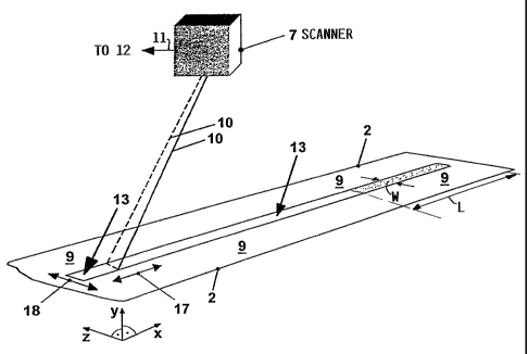
Fig. 1 shows a schematic perspective view of a scanner
positioned for scanning a first joining surface area
of a skin or shell section to be joined to a stringer;
Fig. 2 shows a perspective view of a scanner positioned for
scanning a joining surface area of the stringer to be
joined to the surface area of the skin section of Fig.
I;
7 -
CA 02466003 2004-05-03
Fig. 3 shows a sectional view through a stringer positioned
on a skin section to illustrate the formation of a
joining gap between the two joining surface areas
which gap must be filled and smoothed or leveled out
prior to the joining;
Fig. 3A is a view similar to that of Fig. 3, however showing
portions of two additional gaps that are open sideways
and must also be filled and smoothed or leveled out
prior to the joining;
Fig. 4 shows a sectional view through a stringer and a skin
section spaced from each other prior to joining to
illustrate that a gap is formed by two gap portions,
whereby one gap portion is present in the joining
surface area of the stringer while the other gap
portion is present in the joining surface area of the
skin section;
Fig. 4A is a view similar to that of Fig. 4, however showing
that gap portions can also be formed by a topography
which has projecting hills so that the gap portions
are formed in the neighboring dales;
Fig. 5 shows perspectively a skin or shell section with a
joining surface area that has been smoothed out by
filler material prior to the actual joining;
8 -
CA 02466003 2004-05-03
Fig. 6 is a view similar to that of Fig. 5, but now
illustrating the positioning of a stringer with its
joining surface area facing the joining surface area
of the skin section just prior to joining; and
Fig. 7 shows an embodiment which uses pieces or strips of
solid filler material for filling a gap between a
stringer and a skin section prior to the actual
joining step.
DETAILED DESCRIPTION OF A PREFERRED EXAMPLE EMBODIMENT AND OF THE
BEST MODE OF THE INVENTION
Fig. 1 shows perspectively a first structural component such as
a skin or shell section 2 having a relatively thick wall with an
inwardly facing surface 9. A portion of the inwardly facing
surface 9 of the skin section 2 forms a first joining surface
area 13 that will be joined or bonded by an adhesive to a second
joining surface area 8 of a second structural component 3 such
as a stringer 3 to be described in more detail below. In
practice the first and second joining surface areas 13 and 8 are
not exactly plane due to acceptable manufacturing tolerances.
Thus, it is the purpose of the invention to provide a method to
level out or smooth out any topographic irregularities in the
surface areas 13 and 8 to avoid the formation of air pockets in
the finished joint.
9 -
CA 02466003 2004-05-03
Without such smoothing or leveling air pockets of various
geometric configurations could be formed and it is the purpose
of the invention to avoid such faulty gap formations. For this
purpose the topography of the first joining surface area 13 is
scanned, for example by a laser scanner 7 that directs a scanning
beam 10 onto the first joining surface area 13, whereby the
scanning beam 10 is moved longitudinally as indicated by the
arrow 17 and crosswise to the longitudinal direction as indicated
by the arrow 18. One scanner can be used for sequential scanning
of both structural components. Two scanners can be used for
simultaneous scanning of both structural components.
The output 11 of the scanner 7 is connected to a control and
evaluating unit 12 shown in Fig. 2. The respective output
signals of the scanner 7 contain the topographic information
regarding the first joining surface area 13. Fig. 1 also shows
symbolically the three coordinates of space x, y, Z. The
topographic information contains gap portion dimensions in the
three directions.
Fig. 2 shows a portion of a stringer 3 in the form of a T-section
with a web 6 and a chord 5. An outwardly facing surface of the
chord 5 forms the second joining surface area 8 which is scanned
by the scanner 7 whose output 11 is also connected to the control
and evaluating unit 12 which is controlled by a central
processing unit (CPU) 16 through a control bus 11A. Regardless,
whether one or two scanners are used, in both instances the
control and evaluating unit 12 generates a calculated control
- 10 -
CA 02466003 2004-05-03
signal on its output 11B which is supplied to a filler material
supply and dosing unit 15 which may also include a material
cutter or the like and a length measuring device as will be
described in more detail below.
The skin section 2 and the stringer 3 are generally made of
carbon fiber reinforced composite materials (CFCs) which have
relatively thick walls sufficient to make these structural
components 2 and 3 stiff or rigid. The skin sections 2 have
generally a concave configuration to fit the contour of the
aircraft body. The stringers 3 may have an I-sectional
configuration or a T-sectional configuration or an H-sectional
configuration.
The final joining takes place with conventional adhesives
preferably under pressure and heat. Adhesive and additional
material plies may be inserted between the two structural
components or rather between the joining surface areas for
beneficially influencing the final joining. Additionally, a
thermal welding may be performed along the edges of the chord
sitting on the joining surface area 13. Referring to Fig. 3 the
formation of a gap 1 and its topography will now be described.
These gaps 1 occur because the joining surface areas 8 and 13 of
the stringer 3 and of the skin section 2 are not exactly plane.
Mechanical planing, for example by mechanical material removal,
involves prohibitive costs and is to be avoided according to the
invention.
- 11 -
CA 02466003 2004-05-03
In Fig. 3 the joining gap 1 has two portions 1' and 1" that are
formed by topographic depressions or hills and dales in the first
joining surface area 13 and in the second joining surface area
8. The first gap portion 1' in the surface 13 of the skin
section 2 is initially separated from the second gap portion 1"
in the surface area 8 of the stringer chord 5 by a line or plane
Li - Ll. The plane Ll - Ll passes through the plane touch areas
TA1 and TA2 between the surface area 9 of the skin section 2 and
the surface area 8 of the stringer chord 5. In the touch areas
TA1 and TA2 there are no depressions that could form air pockets
when the joining is completed. The volume of the joining gap 1
is determined by the sum of the volumes of the gap portions or
depressions 1' and 1" as will be described in more detail below.
For this purpose it is necessary to ascertain the gap width s as
a function of space, namely in the x, y and z directions. This
gap width s varies throughout the gap area.
Fig. 3A illustrates the formation of additional gaps 1A and 1B
due to hills 13' in the topography of the surface 13 of the skin
section 2 and due to hills 8' in the topography of the chord
surface of the stringer 3. These hills 8' and 9' form touch
areas TA3. The additional gaps lA and 1B are formed as valleys
outside these touch areas TA3 whereby again a line or plane Li -
Ll passes through the hill tops, so to speak, to define the
volumes of the respective gap portions above and below this line
or plane Li - Li. Again the gap width s of each gap 1B and 1A
will differ from point to point in the three directions of space
x, Y, z.
12 -
CA 02466003 2004-05-03
Fig. 4 illustrates the formation of the gap portion 1' in the
skin section 2 and the gap portion 1" in the stringer 3.
Incidentally, the stringer 3 may be a spar in an aircraft wing
or a girder or beam forming part of the floor support in an
aircraft body. A vertical depth VD1 is formed in the gap portion
1' of the skin section 2 at a depth point DPi. Varying depths
are formed from depth point to depth point depending on the
surface topography of the surface 8 and 13. More specifically,
the vertical depths VD1 are formed between the depth point DPi
and the line or plane L2 - L2. Similarly, a vertical depth VD2
is formed in the gap portion 1" in the surface 8 of the stringer
chord 5 at a depth point DP2. More specifically, the vertical
depth VD2 is formed between the depth point DP2 and the line or
plane L3 - L3.
Fig. 4A illustrates that the additional gaps 1A and 1B are also
made up of respective gap portions lA' and lA" of the gap 1A and
1B' and 1B" of the gap 1B. The vertical depth VD3 between the
depth point DP3 and the high point HP1 is formed between the
planes L2 - L2 and L4 - L4 at the high point HP1 and depth point
DP3. Similarly, the vertical depth VD4 is formed between the
high point HP2 and the depth point DP4 which are positioned on
the plane L3 - L3 and the plane L5 - L5, respectively. In both
Figs. 4 and 4A the view is in the longitudinal direction of the
stringer 3, hence the width W of the first joining surface area
13 on the skin section 2 is shown. The chord 5 of the stringer
3 has the same width W. The two additional gaps 1A formed by the
gap portions 1A' and 1A" and the gap 1B formed by the gap
- 13 -
CA 02466003 2004-05-03
portions 1B' and 1B" are open laterally when the stringer 3 with
its chord 5 is pressed onto the joining surface area 13 of the
skin section 2.
Fig. 5 shows perspectively a skin section 2 having an inwardly
facing, somewhat concave surface 9 with the first joining surface
13. Two gap areas have been filled with filler material 14. The
calculation of the required quantity or rather volume of filler
material will be described in more detail below. Two portions
8' and 8" of the second joining surface area 8 of the stringer
3 have also been smoothed out as symbolically shown in Fig. 5.
The filler material 14 is, for example a filler powder or paste
that has been smoothed into the topographic depression areas of
the first joining surface area 13.
Fig. 6 shows the stringer 3 in a position just prior to
contacting with its second joining surface area 8 the first
joining surface area 13. The stringer 3 has, for example a
T-cross-sectional configuration and the chord 5 faces with its
surface area 8 the surface area 13.
Fig. 7 shows a gap 1 that is amenable for being filled with
pieces 14A of filler material rather than with a filler powder
or paste.
In order to calculate the volume of each joining gap 1, 1A, 1B
or joining gap portions 1A', lA", 1B' and 1B" it is necessary to
obtain the topographical information of the areas that are
- 14 -
CA 02466003 2004-05-03
congruent with these joining gaps. The gap depths varies
throughout the gap area unless a particular topographical
depression has a uniform depth throughout the area covered by the
particular topographical depression. In order to obtain the
required topographical information the invention teaches to scan
the joining surface areas prior to joining.
The topographical information is based on the length L and width
W of a joining surface area portion that requires smoothing out
or leveling with a filler material. This information is also
based on the varying vertical depths VD1 and VD3 of the gap
portions 1', lA' and 1B' in the first structural component 2 such
as a skin or shell section. This information is also based on
the varying vertical depths VD2 and VD4 of the gap portions 1",
lA" and 1B" in the second structural component 3 to be joined
with the first structural component 2. In case only one of the
joining surface 3 areas to be joined comprises topographic
irregularities in its surface, information will be provided only
for the joining surface that has such irregularities which
require filling and smoothing out with a filler material. It
does not matter which of the two joining surface areas is smooth
since both joining surface areas will be scanned. It is then
necessary merely to calculate the volume and configuration of one
gap portion rather than of two gap portions that together form
a gap 1 or 1A or 1B. When one of the joining surfaces is
completely plane the gap is then formed by one gap portion in the
other joining surface or vice versa. The probability that both
joining surfaces are completely plane and smooth is small.
- 15 -
CA 02466003 2004-05-03
Referring to Fig. 4, the above mentioned varying, vertical depths
including VD1 are determined by the scanning between depth points
DPl and the plane L2 - L2 coinciding with the plane portions of
the joining surface area 13. The vertical, varying depths
including VD2 are determined by scanning between depth points DP2
and a line or plane L3 - L3 coinciding with the plane portions
of the joining surface area 8 of the second structural component
such as a stringer 3, a spar, a beam or a girder.
Referring to Fig. 4A, the varying, vertical depths including VD3
are determined by the scanning between high points HP1 of the
topography of the gap portion 1B' and depth points DP3. The high
points HP1 coincide with the line or plane L2 - L2. The depth
points DP3 coincide with a line or plane L4 - L4. Thus, these
depths VD3 are measured between the two planes L2 and L4 outside
the touch areas 8' and 13'. Similarly, the varying vertical
depths VD4 are determined by the scanning between the high points
HP2 and the depth points DP4. The high points HP2 coincide with
a line or plane L3 - L3. The low or depth points DP4 coincide
with a line or plane L5.
Referring to Fig. 1, the topographic informations acquired by the
scanner 7 are transmitted for example through a data bus 11 to
the processing and evaluating unit 12 which is connected, for
example, by a further data bus 11A to a central processing unit
(CPU) 16. The topographic informations of two joining gap
portions for example 1A' and 1A" forming a gap lA are evaluated
by the processing and evaluating unit 12 under the control of a
- 16 -
CA 02466003 2004-05-03
computer 16. The CPU 16 has stored in its memory the required
program or programs and any parameters required for the
topographical calculations to obtain the quantity or volume and
configuration of the gap portions 1', 1", 1A', 1A", 1B', 1B" and
to further obtain the volume and configuration of the respective
gaps 1, 1A, 1B. The unit 12 also converts the just described
topographical information into control signals for a filler
material supply dosing unit 15 connected to the unit 12 by a
further data bus 11B. The filler material supply and dosing unit
15 provides the exact quantity, in terms of gap volume and gap
configuration, of filler material for filling and smoothing any
particular gap. The filler material may be a powder or paste or
it may be solid in the form of strips. For dosing the correct
length of a strip filler material the unit 15 includes a cutter
such as an ultrasound cutter for cutting filler material pieces
14A shown in Fig. 7. The required length of the individual
filler material pieces 14A may be measured by any suitable length
measuring device, e.g. an ultrasound length meter that provides
respective control signals for the cutter not shown.
The dosed quantities of filler material may be transferred
manually or by suitable robot machinery to the joining surface
areas. Such machinery may be remote controlled. Where two gap
portions are forming a gap, as described above, the quantity of
filler material in powder form deposited on one gap portion will
be sufficient to fill both gap portions when the second
structural component 3 with its joining surface area 8 is pressed
down on the first joining surface area 13 of the first structural
- 17 -
CA 02466003 2004-05-03
component 2. Where paste or otherwise sticking filler material
is used the filler material will remain attached to the surface
8 even if the stringer 3 is turned around so that the surface 8
faces down for contacting the surface area 13.
Rather than using one or two laser scanners 7 other optical
topography measuring systems may be used, such as photogrammetry
systems, light section methods using light line projections, and
any other suitable optical measuring system.
The filler material is, for example, a glass fiber reinforced
composite material (GFC), a carbon fiber reinformed composite
material (CFC) or any other suitable material. Further, the
present method is equally practicable for any materials of which
the first and second structural components 2 and 3 may be made,
such as GFCs, CFCs, metals, particularly lightweight metals such
as aluminum. Further, the filler material strips may be coated
with an adhesive bonding material such as a resin film, whereby
the pieces 14A can be handled just like a sticker. Different
filler materials and different filler material consistencies,
e.g. powders, pastes, strips, stickers may be used singly or in
combination.
The invention assures that any kind of gap with any kind of
topography is completely filled and air inclusions are avoided.
Extra filler material may be placed along the edges of the chord
of the second structural component to form tight seams which may
for example be formed or reinforced by thermal welding. Another
- 18 -
CA 02466003 2004-05-03
advantage of the invention is seen, in that the present method
can be used for joining thick walled rigid structural components
and for smoothing out deep and wide gaps. Further, the present
method can accommodate substantial structural component surface
tolerances which are required in the manufacturing of such
structural components for economic reasons.
Incidentally, if one joining surface of two joining surfaces does
not happen to have any topographic irregularities, the respective
topographic information resulting from the scanning will be zero.
The calculation is then based on the topography of one gap
portion that needs to be filled and smoothed out to avoid air
pockets.
Although the invention has been described with reference to
specific example embodiments, it will be appreciated that it is
intended to cover all modifications and equivalents within the
scope of the appended claims. It should also be understood that
the present disclosure includes all possible combinations of any
individual features recited in any of the appended claims.
- 19 -