Note: Descriptions are shown in the official language in which they were submitted.
CA 02466202 2004-05-03
TITLE OF THE INVENTION
Fixing Apparatus
BACKGROUND OF THE INVENTION
Field of the Invention
The present invention relates to a fixing apparatus, and more
particularly to a general-purpose fixing apparatus for fixing a prescribed
component to an object.
Description of the Background Art
A number of fixing apparatuses have conventionally been proposed
for a bicycle, in order to attach components such as a headlamp, a speed
meter or the like to a handlebar or the like. For example, Japanese Patent
Laying-Open No. 8-113175 (U.S. Patent No. 5,735,441) proposes a fixing
apparatus composed of three separate portions fixed to one another. The
three separate portions are (a1) a handlebar mount portion (a2) an
intermediate portion and (a3) a component attachment portion fixed to the
handlebar mount portion with the intermediate portion interposed. The
handlebar mount portion (a1) located in a root portion of the fixing
apparatus includes a pipe securing portion clamping a pipe portion of the
handlebar from an outer circumference, and a screw mechanism fixing the
intermediate portion (a2) while allowing a horizontal rotation thereof
within a prescribed range. The intermediate portion (a2) includes a screw
mechanism secured to the handlebar mount portion (a1) and a rail portion
to which the component attachment portion (a3) is mounted. The
component attachment portion (a3) includes an engagement groove
engaging to the rail of the intermediate portion, a stopper mechanism fixing
the engagement to that rail, and a component fixing screw mechanism for
fixing a component.
The fixing apparatus described above allows for easy attachment of
components to a handlebar or the like while adjusting an orientation of
components such as a headlamp.
In addition, Japanese Utility Model Registration No. 2602582
proposes a fixing apparatus with an excellent adaptability to an object,
using a band-like securing component so as to attain easy attachment of
- 1-
CA 02466202 2004-05-03
components to objects of a variety of sizes. In this fixing apparatus, two
bands having each one end connected to each other are wound on the outer
circumference of a pipe. The fixing apparatus includes a first band having
a convex portion formed on the outer circumference side of an end portion
and a second band having a concave portion formed on an inner
circumference side of the end portion. End portions without convex and
concave portions of the first and second bands are connected by a screw to
each other, and end portions with the convex and concave portions of the
first and second bands are pulled through a member. Accordingly, the
convex portion is inserted in the concave portion, and engagement is thus
achieved. Two bands fasten the object portion in this manner.
Consequently, components can be fixed to the pipe, which is the object
portion, while the outer circumference of the pipe is pressed with the bands.
With the use of this fixing apparatus of a single-type, a headlamp or
a speed meter can be fixed to a variety of types of bicycles with a different
size.
On the other hand, it is difficult to perform attachment, removal,
loosening, and tightening with the conventional fixing apparatus as
described above. For example, in the case of the fixing apparatus having
three separate sections above, a mechanism for the component attachment
portion (a3) or the intermediate portion (a2) tends to be complicated, and
the manufacturing cost is not readily reduced. Moreover, it is difficult to
achieve firm fastening because many parts are interposed. In addition,
further increased tightening or the like is difficult when a band-like
securing component is used. Significant change with time can be observed
in maintaining a fastened state attained by engagement of the convex
portion and concave portion, and it is difficult to maintain strong fastening
force. Therefore, a fixing apparatus readily maintaining strong fixation
with a simplified mechanism in a stable manner for a long time without
limited to an application to a bicycle has been desired.
SUMMARY OF THE INVENTION
An object of the present invention is to provide a fixing apparatus
capable of maintaining strong fixation with a simplified mechanism in a
-2-
CA 02466202 2004-05-03
stable manner for a long time.
A fixing apparatus according to the present invention fixes a
component to an object. The fixing apparatus includes a plurality of arms
supported on one end, having free another end, and capable of changing a
range of enclosure so as to grasp the object a base member supporting the
plurality of arms and an arm driving member changing a position relative
to the base member, and pressing the plurality of arms with its edge to
change the range of enclosure by the arms.
With the above-described structure, the object can be grasped firmly
by an extremely simplified mechanism, and this grasp state can be
maintained. Accordingly, firm fixing can be achieved with bare hands, for
example. The range of enclosure by the arms above refers to a range
enclosed by two arms if two arms are employed, for example. If three or
more arms are provided, the range of enclosure by the arms refers to a
range enclosed by three or more arms.
The foregoing and other objects, features, aspects and advantages of
the present invention will become more apparent from the following
detailed description of the present invention when taken in conjunction
with the accompanying drawings.
BRIEF DESCRIPTION OF THE DRAWINGS
Fig. 1 illustrates a fixing apparatus fixing a headlamp to a
handlebar of a bicycle in an embodiment of the present invention.
Fig. 2 is a partial cross-section along the line II-II in Fig. 1.
Fig. 3 illustrates a fixing apparatus fixing a speed meter to a
handlebar of a bicycle in an embodiment of the present invention.
Fig. 4 illustrates a state in which an arm driving member (nut) is
used in the fixing apparatus in Fig. 1.
Fig. 5 illustrates a connection mechanism for arms in the fixing
apparatus in Fig. 1.
Fig. 6 illustrates a state in which the arms attempt to grasp an
object portion in the fixing apparatus in Fig. 1.
Fig. 7 is a cross-sectional view along the line VII-VII in Fig. 4.
Fig. 8A shows an example in which the object portion has a small
-3-
CA 02466202 2004-05-03
diameter.
Fig. 8B shows an example in which the shape of the object portion
matches to an arc shape of the arm.
Fig. 8C shows an example in which the object portion has a large
diameter.
DESCRIPTION OF THE PREFERRED EMBODIMENTS
In the following, an embodiment of the present invention will be
described with reference to the figures. Fig. 1 shows a state in which a
headlamp is fixed to the handlebar of a bicycle with the fixing apparatus in
the embodiment of the present invention. A fixing apparatus 10 mounted
with a headlamp 50 grasps the outer circumference of a pipe-like handlebar
30 with an arm 1 driven by an arm driving member 5 so as to fix headlamp
50 to handlebar 30.
Fig. 2 is a partial cross-section of a portion fixing the headlamp,
along the line II-II in Fig. 1. A male screw thread is formed on the outer
circumference of a base member 2. In an upper end portion of the base
member, headlamp 50 is screwed to be fit and mounted. Arm driving
member 5 having a female screw thread cut on its inner circumference is
screwed to the lower end of base member 2, to press two arc-like arms 1
facing to each other. Then, a stress is applied to the arms, which in turn
press handlebar 30.
Fig. 3 shows a state in which a speed meter 51 is fixed to handlebar
with fixing apparatus 10 in the embodiment of the present invention.
Speed meter 51 is fixed to one of two arms 1. Fixing may be achieved with
25 a screw or an adhesive. Whereas the fixing apparatus shown in Fig. 1 has
grasped the handlebar from above along a direction of gravity, fixing
apparatus 10 shown in Fig. 3 grasps the handlebar from the side so as to
intersect the direction of gravity.
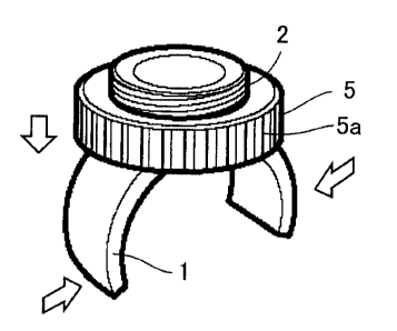
Fig. 4 is a perspective view illustrating the fixing apparatus of the
30 present embodiment. In Fig. 4, a rotation pin 3 serving as a connection
member connecting each one end of a plurality of arms to each other passes
through the center (axis line) of tubular base member 2, and opposite ends
of the rotation pin are fixed to the tubular portion. The end portions of two
-4-
CA 02466202 2004-05-03
arc-like arms 1 facing to each other are pivotably attached to rotation pin 3.
As a structure for an arm end portion in which two arms facing to
each other are pivotably connected to rotation pin 3, a structure as shown in
Fig. 5 may be employed, for example. In the end portions of the two arms
facing to each other, a convex portion la and a concave portion 1b
complementary to each other are formed, and convex portion la is inserted
into concave portion lb. A hole le through which the rotation pin
penetrates is provided in the center of thickness of convex portions of both
arms. Rotation pin 3 passing through the hole provided in base member 2
is inserted into hole lc to implement a hinge structure along with two arms.
Rotation pin 3 attains a function as a connection member connecting two
arms. Base member 2 supports two arms by supporting rotation pin 3
serving as the connection member. In other words, base member 2
supports the hinge structure described above.
As a variation of the above-described example, an arm structure
including two arms described above may be formed as one piece by integral
molding. In the arm structure manufactured by integral molding, a
connection portion to which two arms are connected (root portion) has a
smaller thickness than that of an arm portion so as to have smaller rigidity.
That is, the connection portion is more likely to be elastically deformed
when the arms are driven by the arm driving member. The integrally
formed arms are placed on a shaft such as a pin or a bar-like member so as
to straddle the connection portion (root portion). In other words, the arm
structure is suspended from the shaft at the root portion.
In such a structure, when edges of the arm driving member abut on
the respective arms to narrow the range of enclosure by two arms, the shaft
of the bar-like member or the pin fixed to the base member supports the
connection portion (root portion) of the two arms against the stress applied
from the arm driving portion. Here, the connection member is
implemented by the connection portion (root portion) of the two arms and
the shaft such as the pin or the bar-like member.
In the arm structure manufactured by integral molding described
above, it is not necessary to pass the rotation pin through the end portions
-5-
CA 02466202 2004-05-03
of the arm. Therefore, the pin and the base member are also
advantageously manufactured as one piece by integral molding.
A metal such as a variety of steels including stainless steel,
aluminum, titanium, magnesium alloy, or the like may be used for the
rotation pin described above. In addition, a variety of plastics, engineering
plastic, metal, or the like may be used for the base member, the arm driving
member (nut), and the arm. In selecting a material such as plastic,
engineering plastic or metal, strength, elastic modulus, rigidity, durability,
or the like is taken into account.
When the hinge structure including two arms is formed with the
rotation pin described above, the rotation pin and the base member above
may be manufactured by integral molding. The two arms are, for example,
provided with a groove in order to avoid a problem during fastening, and
the arms can pivotably be attached to the rotation pin.
Fig. 6 shows a state in which a nut 5 serving as the arm driving
member is screwed and moved toward the arms to press the same, so that
the arms exert fastening force to the object portion (not shown). Here,
desirably, nut 5 has a large outer diameter in order to allow turning and
tightening of the same with bare hands. Moreover, grooves 5a may be
provided on the outer circumference of the nut along the axis of the tube.
Fig. 7 is a cross-sectional view along the line VII-VII in Fig. 4.
Arms 1 are supported by base member 2 along with rotation pin 3. The
arms are pressed by arm driving member 5 screwed to base member 2.
Accordingly, the range of enclosure by the arms is narrowed to clamp the
object portion, thereby attaining firm grasping.
Figs. 8A to 8C show three examples. Fig. 8A shows an example in
which the pipe has a small diameter Fig. 8B shows an example in which
the pipe has an intermediate diameter and Fig. 8C shows an example in
which the pipe has a large diameter. In each example shown in Figs. 8A to
SC, a position A where arm driving member 5 comes in contact with arm 1
is closer to the object portion than to rotation pin 3 serving as the arm
connection member. By implementing such a positional relation in a fix
state, the arms can readily grasp or clamp the object portion. As shown in
-6-
CA 02466202 2004-05-03
Figs. 8A to 8C, the larger diameter the object portion has, the closer the
contact position A described above comes toward rotation pin 3 serving as
the connection member. Therefore, the distance between the tip ends of
the arms approaches the diameter of the object portion, and hence, fixation
force of the arms is made-s~,aller
Magnitude of the force with which arms 1 grasp the object portion is
not determined by the positional relation described above. Instead, factors
such as a contact length or a contact area of arms 1 and object portion 30
significantly affect the grasping force. Among the three examples shown
in Figs. 8A to 8C, the contact length or the contact area described above is
largest in Fig. 8B where the arc shape of arm 1 matches the shape of the
object portion. Here, a maximum grasping force or fixation force is
attained.
By using the above-described fixing apparatus with a simplified
structure, a headlamp or a speed meter can readily and firmly be fixed to a
handlebar or the like.
Other embodiments of the present invention will now be described
successively, including the features set forth in the embodiment above.
The following structure may be employed. The base member and
the arm driving member are tubular members. A male screw thread is cut
on the outer circumference of the base member, and a female screw thread
is cut on the inner circumference of the arm driving member. The arm
driving member is screwed to the base member.
With such a structure, the tubular arm driving member is rotated
around the base member and moved along the axis of the tube. Then, the
end portion of the arm driving member is pressed against the arms, and the
arms can firmly grasp the object portion. This fixing operation is
extremely simplified.
In addition, a connection member connecting ends of the plurality of
arms described above may be provided, and the base member may support
the arms with the connection member interposed.
By connecting the ends of the arms with the rotation pin, further
simplified structure is obtained. Then, tightening the arm toward the
CA 02466202 2004-05-03
object portion can be facilitated.
The above-described connection member is provided at one end
portion of the base member. The arm is arranged outwardly from the one
end portion. The arm driving member can come in contact with the arm in
a position outside the connection member at the one end portion of the base
member while it is fixed to the object.
With this structure, a stress for the arm to grasp the object can
readily be applied by driving the arm driving member. As a result, the
arms can grasp the object further firmly.
The following structure may be employed. The connection member
described above is provided as the rotation pin provided in the base member.
Two arc-like arms facing to each other are pivotably attached to the
rotation pin at each one end, so as to grasp a pipe along the outer
circumference.
With this structure, the arms are fixed to the base member with a
simplified structure, and can readily and firmly be fixed to the pipe-like
object portion.
Opposing two cut portions are provided in end portions on the sides
where the arms are located, of the tubular base member. The ends of the
rotation pin are fixed to opposing tube ends except for the cut portions, and
the arm can be arranged so as to face the cut portion.
With this structure, the arm can be shaped like an arc, and can be
arranged so as to pass through the cut portion or outside thereof.
Therefore, the arm driving member can press the arms without moving the
arm driving member as far as a position close to the end of the base
member. Accordingly, reaction force applied from the arm to the arm
driving member when the arms grasp the object portion can be born also by
the base member to a large extent in a stable manner. Thus, firm fixing
can readily be attained.
Grooves along the axis of the tube may be provided on the outer
circumference of the arm driving member. With this structure, the arm
driving member can readily be rotated with bare hands so as to press the
arms. Strong fastening force can thus be applied to the arms.
_8_
CA 02466202 2004-05-03
Though an example of two arc-like arms facing to each other has
been described in the embodiment of the present invention described above,
the embodiment of the present invention is not limited thereto. The fixing
apparatus according to the embodiment of the present invention only
requires a plurality of arms, and therefore three or four arms may be
provided, for example. In such a case, any structure for connecting the
arms to the connection member may be employed so long as the end
portions of the arms are connected to each other. For example, such a
structure that end portions of three arms may be concentrated to one
location to exhibit a cone shape may be employed. If the three arms are
formed integrally as one piece by integral molding, the end portions of the
arms concentrated to one location and an arm support member causing
those end portions to be supported by the base member implement the
connection member described above. If the connection member is arranged
as described above, the manufacturing method is simplified, and fastening
of the arm to the object portion can be facilitated.
The arm may be formed with an elastic member having prescribed
rigidity. In such a case, the arm is driven by the arm driving member to
undergo elastic deformation, thereby narrowing the range of enclosure to
grasp the object potion. The object portion does not need to have a
pipe-like shape, and it may be a tip end portion of a bar, for example. The
fixing apparatus according to the present invention may be adapted to any
device or instrument as the object portion, without limited to each part of a
bicycle.
The fixing apparatus according to the present invention can
maintain strong fixation with a simplified mechanism in a stable manner
for a long time without limited to an application to a bicycle. Therefore,
widespread use of this fixing apparatus in an industry or a household is
expected.
Although the present invention has been described and illustrated
in detail, it is clearly understood that the same is by way of illustration
and
example only and is not to be taken by way of limitation, the spirit and
scope of the present invention being limited only by the terms of the
appended claims.
_9_