Note: Descriptions are shown in the official language in which they were submitted.
CA 02466221 2004-05-04
OR File No. 17064-2CA
-2-
HUMANE ANIMAL TRAP, AND METHOD OF USE THEREOF
FIELD OF THE INVENTION
This invention relates to traps for catching animals in the wild, and in
particular to so-called « humane » traps that minimize or prevent injuries to
animals sustained when and after an animal is caught while providing reliable
physical retention of the animal about the trap.
BACKGROUND OF THE INVENTION
Traps intended for the catching of animals - mainly mammals - in the
wild, consist essentially of snares, of facing jaw traps. The jaws of some
conventional traps are provided with sharp teeth, for penetrating deep into
and
maintaining firmly one of the legs of the animal caught by the trap. The
pressure
applied by those jaws is always very strong, which has the effect of severely
wounding the trapped animal, before release by the hunter. Some of these
animal
may even die of their injuries before the hunter comes back to his trap.
Snares
thrown too quickly may also cause the same results. Moreover, these types of
traps do not allow one to carry out a selective hunting whereby the animals so
trapped cannot be released, because the extent of bodily injuries sustained by
these animals would be such as to require expensive veterinary cares that are
beyond the means of most hunters. Also, domestic animals, or animals protected
under law (e.g. endangered species) may be accidentally trapped and injured or
killed.
Alternate trap embodiments that attempted to deal with the above-noted
bodily injuries to the caught animal, have several drawbacks. One such
drawback
is that these modified traps are too easy for the trapped animal to open and
freely
escape therefrom, and thus are unreliable. Existing humane traps still do
inflict
CA 02466221 2004-05-04
-3-
OR File No. 17064-2CA
some bodily injuries, although to a lesser degree than conventional traps with
sharp teeth jaws. The unstable rigid frame of some humane traps can hamper the
effective operation of the slip-knot lace involved in the animal retention.
Some
other humane traps can also be rendered ineffective by becoming damaged under
the load of a more powerful wild animal, such as a wolf.
United States patent No. 1,031,728 issued in 1912 (inventor Obiols) and
United States patent No. 4,389,807 issued in 1983 (inventor Novak) both show
an animal trap which comprises a snare which lies on the ground in the case of
the Novak device, and which lies on the ground-resting frame in the case of
the
Obiols patent. A trigger located centrally of the snare will release a spring-
loaded
arm when stepped upon, so as to pull the snare up on the animal's leg. This
type
of trap is rather conventional, and has been found to be unreliable, since the
animal often has enough time to retrieve his leg once the mechanism is
triggered
and before he is ensnared. Also, this trap often moves or tilts when stepped
on by
the animal, which will result in the spring-loaded arm carrying the snare
along
the ground instead of up the animal leg. Finally, an animal standing above the
pivotable arm may prevent the trap from functioning.
United States patent No. 4,581,844 issued in 1986 (inventor Torkko)
discloses an animal trap which is similar to the above-mentioned Obiols and
Novak devices, with the exception that the snare rests on a unitary integral
circular frame ring that is attached to the spring-loaded pivotable arm. Thus,
upon the animal triggering the trap, the frame ring carries the snare in its
upwards
pivotal displacement along the leg of the animal, to increase the likelihood
that
the animal will indeed be ensnared. Although animals may indeed be caught
more easily with such a snare, it remains unreliable since the pivotal motion
of
the long spring-loaded arm is too slow to ensnare some animals and animals
standing above the pivotable arm may prevent the trap functioning. Moreover,
and more importantly, the Torkko snare will often injure animals, since the
rigid
frame of the trap will remain caught on the animal's leg, due to the fact the
CA 02466221 2004-05-04
OR File No. 17064-2CA
-4-
animal leg extends through the rigid frame ring. When the animal realizes that
he
has been ensnared, he will kick and struggle to break free and consequently is
likely to injure himself by flailing the rigid trap frame about.
United States patent No. 5,907,922 issued in1999 (inventor Belisle) shows
and animal trap comprising a ground resting frame carrying a pair of opposite,
pivotable, spring-loaded jaws. The jaws will close themselves upon the animal
stepping on a central trigger. A snare lace, initially located under the jaws,
will
close upon the animal's leg due to the animal struggling to break free from
the
rigid frame. However, a problem with the Belisle trap is that the rigid frame
will
more often than not remain attached with the snare lace on the animal's leg.
As
the animal kicks and struggles to break free, he will involuntarily flail the
rigid
frame against himself, injuring himself.
SUMMARY OF THE INVENTION
The invention relates to a trap for use with a snare for ensnaring
animals, the snare of the type including a loop lace, a loop lace anchoring
line
linked to the loop lace and anchoring means for fixedly anchoring the
anchoring
line, said trap comprising:
- a ground-resting frame;
- first and second jaws pivotally carried by said frame, said jaws
being movable between an opened position in which said first and
second jaws are spread apart, and a closed position in which said
first and second jaws are closed against each other;
- releasable biasing means that bias said jaws towards said closed
position;
- a lock movable between a first operative position, in which it
retains said jaws in said opened position against the bias of said
biasing member, and a second inoperative position in which it
CA 02466221 2004-05-04
OR File No. 17064-2CA
-5-
releases said jaws to allow them to move towards said closed
position under the bias of said biasing means;
- a lock trigger for forcing said lock towards said inoperative
position upon a load being applied thereon; and
- a loop lace channel for carrying the snare loop lace, said loop lace
channel comprising a first channel portion on said first jaw and a
second channel portion on said second jaw, said first and second
channel portions thus being movable with said first and second
jaws, respectively, between said opened and closed positions of
said jaws for carrying the loop lace with said jaws from said
opened position towards said closed position, for positively moving
said loop lace around an animal leg upon said jaws being triggered
to move into said closed position on the animal leg.
In on embodiment, the trap further comprises a biasing means disabling
system for selectively disabling said biasing means thus selectively canceling
its
biasing action on said jaws.
In one embodiment, said biasing means is a resilient U-shaped spring
member defining a first and a second leg, with said first leg releasably
engaging a
recess in said frame and with said second leg engaging said first and second
jaws
to bias said jaws towards said closed position, said biasing means disabling
system comprising a spring member anchor line attached to said spring member
at a first end thereof and destined to be fixedly anchored at a second end
thereof
whereby said spring member first leg can be forcibly removed from said recess
to
disable said biasing means thus selectively canceling its biasing action on
said
jaws.
The invention also relates to a trap ensnaring animals comprising:
CA 02466221 2004-05-04
OR File No. 1'7064-2CA
-6-
- a snare comprising a loop lace, a loop lace anchoring line linked to
the loop lace and anchoring means for fixedly anchoring the
anchoring line;
- a ground-resting frame;
- first and second jaws pivotally carried by said frame, said jaws
being movable between an opened position in which said first and
second jaws are spread apart, and a closed position in which said
first and second jaws are closed against each other;
- releasable biasing means that bias said jaws towards said closed
position;
- a lock movable between a first operative position, in which is
retains said jaws in said opened position against the bias of said
biasing member, and a second inoperative position in which it
releases said jaws to allow them to move towards said closed
position under the bias of said biasing mean;
- a lock trigger for forcing said lock towards said inoperative
position upon a load being applied thereon, and
- a loop lace channel carrying said snare loop lace and comprising a
first channel portion on said first jaw and a second channel portion
on said second jaw, said first and second channel portions thus
being movable with said first and second jaws, respectively,
between said opened and closed positions of said jaws and carrying
said loop lace with said jaws from said opened position towards
said closed position, for positively moving said loop lace around an
animal leg upon said jaws being triggered to move into said closed
position on the animal leg.
CA 02466221 2004-05-04
OR File No. 17064-2CA
_7_
In one embodiment, said biasing means is a resilient U-shaped spring
member defining a first and a second leg, with said first leg releasably
engaging a
recess in said frame and with said second leg engaging said first and second
jaws
to bias jaws towards said closed position, said trap further comprising a
spring
member anchor line attached to said spring member at a first end thereof and
destined to be fixedly anchored at a second end thereof whereby said spring
member first leg can be forcibly removed from said recess to disable said
biasing
means thus selectively canceling its biasing action on said jaws.
In one embodiment, the trap further comprises a temporary retaining
device on said anchoring line intermediate said loop lace and said anchoring
means, said temporary retaining device being destined to be releasably
anchored,
the length of said loop lace plus the length of said loop lace anchoring line
between said loop lace and said temporary retaining device being equal to or
less
than the length of said spring member anchoring line, and the length of said
spring member anchoring line being less than the length of said loop lace
anchoring line.
In one embodiment, said temporary retaining device is a ground peg for
releasable engagement of said ground peg in the ground.
BRIEF DESCRIPTION OF THE INVENTION
In the annexed drawings:
Figure 1 is a perspective view of a preferred embodiment of animal trap,
shown in the cocked condition, and associated ground peg;
Figure 2 is a top plan view of the animal trap;
Figure 3 is a perspective view of the animal trap, shown in its uncocked
condition, with the jaws thereof shown as being drawn together against the leg
of
an animal illustrated in phantom lines, and suggesting the release of the lace
first
ground peg under load from the trapped animal;
CA 02466221 2004-05-04
OR File No. 17064-2CA
_g_
Figure 4 is a view similar to figure 3, but a smaller scale and suggesting
how the lace second ground peg and ground peg remain anchored into the ground
as the trapped animal leg releases the uncocked trap;
Figure 5 is an enlarged view of a wire section of the trap;
Figure 6 is an enlarged cross-sectional view taken along line VI - VI of
figure 5;
Figure 7 is an enlarged sectional view of the release arm assembly of the
trap;
Figure 8 is an enlarged sectional view taken along line VIII-VIII of figure
7; and
Figures 9 and 10 are views similar to fig. 8, but suggesting how the release
arm of the trap can detach from the trap frame.
DETAILED DESCRIPTION OF THE PREFERRED EMBODIMENT OF
THE INVENTION
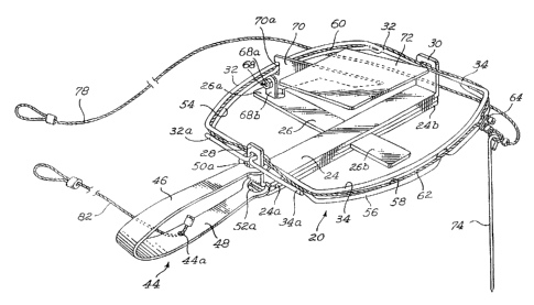
Figures 1-4 show an animal trap 20 according to the present invention.
Trap 20 includes a planar rigid cross-shaped frame 22 defining two
perpendicular
elongated legs 24, 26 having corresponding opposite end portions 24 a, 24b,
and
26a, 26b, respectively. Legs 24, 26 of frame 22 are adapted to lay That
against the
ground. Each of the frame two opposite end portions 24a, 24b, includes a short
upturned flange 28, 30. Each flange 28, 30, includes a bore 28a, 30a,
receiving
the opposite elbowed hook end portions 32a, 34a, and 32b, 34b, respectively of
a
pair of elongated rigid U-shape wire members 32, 34. Each wire member 32, 34,
extends from and joins one flange 28 to the other flange 30. Hook end portions
32a, 34a, should be much longer than hook end portions 32b, 34b. Frame leg end
portion 24a also includes a recess 36 (figs 8-10) beneath the corresponding
said
upturned flange 28. Recess 36 defines a flooring 38, a top wall 40 and a mouth
42 opening orthogonally relative to the orientation of upstanding flange 28.
The
CA 02466221 2004-05-04
OR File No. 17064-2CA
-9-
recess flooring 38 includes an intermediate projecting bulge or boss 38a,
located
spacedly from the recess mouth 42 and from the top wall 40 thereof.
An elongated spring-loaded U-shape handle member 44 is further
provided on trap 20, defining two legs 46 and 48, having opposite end portions
50 and 52, respectively, each having a large circular aperture SOa, 52a. In
the
released, uncocked condition of the trap 20 illustrated in figure 3, the two U-
shape wire legs 32, 34 extend in generally upright condition substantially
parallel
to one another; the opposite ends 50, 52 of the two legs 48, 50 of spring-
loaded
handle member 44 are at their farthest apart position; and upper circular
aperture
SOa is slidingly engaged by the four segments of elbowed hook end portions
32a,
34a. Alternately, in the trap cocked condition illustrated in figures 1 and 8,
the
two U-shape wire legs 32, 34, are spread apart in a generally coplanar fashion
to
form open jaws; the opposite ends of legs 46, 48 of the spring member 44 are
brought closer toward one another, slidingly along hook end portions 32a, 34a,
to
surround flange 28 beneath the plane formed by the coplanar open jaws 32, 34;
the spring member lower end portion 52 is snap-fitted into recess 36 with the
spring member aperture 52a being partially engaged by bulge 38a; and the
spring
member lower end portion 52 extends generally coplanar to the trap frame leg
24.
According to an important feature of the present invention, figures 8 to 10
of the drawings suggest that the lower end 52a of spring member 44 located
inside the trap frame recess 36, should remain engaged into recess due to the
spring loading of spring member 44, during cocking as well as uncocking of the
trap 20. It is difficult to release spring member lower end 52a from frame
recess
36, because it is webged therein by the spring load of spring member 44 and
spring member aperture 52 a is engaged by bulge 38a. However, a pivotal
displacement of handle member 44 about an axis extending through frame recess
38 and perpendicular to the general place defined by frame 24, 26, will allow
spring member aperture 52a to disengage from bulge 38a with relative ease. A
CA 02466221 2004-05-04
OR File No. 17064-2CA
-10-
slight pull on handle member 44 may then dislodge spring member 52 from
recess 38.
'The intermediate U-shape section of each jaw 32, 34, includes an
additional U-shape wire member 54, 56, respectively. Wire members 54, 56,
merge at their opposite ends integrally with the jaw wires, 32, 34, but
otherwise
extend generally spacedly parallel from the main portion of the jaw wires 32
and
34 to form therebetween a channel 58 and 60, respectively. Shallow reinforcing
bridges 54a, 56a, link arms 32 and 54, and arms 34 and 56, respectively, at
selected spaced intervals therealong. Alternately, the wire members 54, 56
could
abut along their full length (not shown) against the jaw wires 32, 34, but
then
wires 32, 34, 54 and 56 should be sized and shaped relative to one another as
to
define therebetween a U-shape groove or channel (not illustrated) that would
be
functionally equivalent to channels 58, 60. Channels 58, 60, are adapted to
receive and releasably retain a snare or loop lace 62.
Double jaws 32, 54, 34, and 56, are made from cross-sectionally circular
or ovoidal shape, without any sharp edge, to prevent injuries or cuts to the
animal.
As shown in figure l, the flexible yet sturdy elongated lace 62 extends in a
loop co-extensively into channels 58, 60 and against the interior faces (i.e.
facing
one another) of flanges 28, 30. The opposite ends of lace 62 are slidingly
interconnected by a slip-knot attachment member 64. Lace 62 should have a soft
external surface, e.g. a soft plastic sheathing embedding a flexible metallic
core
wire.
To keep the jaws 32, 34, in their cocked coplanar spread apart condition
shown in figure l, against the transverse bias of spring leg 46, there is
provided a
releasable locking means 66. Locking means 66 includes a pivot mount 68,
fixedly mounted to the end portion 26a of ground frame leg 26, and an
elongated
locking arm 70 pivotally carried by the pivot mount 68 for pivotal motion
about
CA 02466221 2004-05-04
-11-
OR File No. 17064-2CA
an axis generally parallel to the plane of ground frame 24, 26. Locking arm 70
includes an end notch 70a, sized for releasable engagement by registering
sections of jaw wires 32, 54. Pivot mount 68 is of friction fit type, i.e.
that
locking arm 70 will stand by its own at any inclined position over underlying
main frame 24, 26, and will not pivot freely about pivot mount 68. Arm 70 will
start pivoting once a load is applied beyond a minimum threshold level, to
forcibly pivot arm 70 about pivot 68.
Preferably, a tension adjusting screw 68a is provided at pivot mount 68, to
adjust the friction fit minimum threshold level required to start moving pivot
arm
70 about pivot 68. As illustrated in figure 2, pivot mount assembly 68, 68a,
may
consist for example of a pair of upright transversely bored bracket plates
68b,
68c, anchored to the outer end portion of main frame leg 26, a bolt 69
extending
transversely through bracket plates 68b, 68c, a pair of nylon washers 71a,
71b,
and a partly tightened nut 73 at the end of bolt 69.
The pivotal load on pivot arm 70 can be applied for example by providing
a trigger plate 72 fixed to the inner end or arm 70 opposite notch 70a.
In use, in the cocked trap condition of figure 1, notch 70a, is engaged by a
section of jaw wires 32, 34, locking arm 70 is upwardly inwardly inclined from
its notch end 70a to its opposite inner end. Jaw 32, 54, abuts against arm 70
in
notch 70a. Spring member lower end 52 engages recess 38, and spring member
upper end 50 is tensioned against jaw 32, 54. Jaw 34, 56 is loose, but will be
manually positioned coplanar with the other jaw 32, 54 and will maintain this
position under its own weight when trap 20 is positioned on the ground. Loop
lace 62 is installed in channel 58, 60.
By applying a downward load against trigger plate 72, as when a wild
animal sets foot on plate 72 to retrieve a bait, the locking arm 70 tilts
downwardly inwardly, thus releasing jaw wires 32, 54 from its notch 70a. This
in
turn enables the spring member 44 to express its upwards bias against the hook
CA 02466221 2004-05-04
OR File No. 17064-2CA
-12-
members 32a, 34a, so as to close the jaws 32, 54 and 34, 56 toward each other
against the wild animal leg L (fig. 3). The lace loop 62 is carried upwardly
against the animal leg by jaws 32, 54 and 34, 56 and still loosely surrounds
the
animal leg L at this point. Lace loop 62 is thus carried spacedly over ground
by
jaws 32, 54, 34, 56, and in turn carries in its upward movement a first
lightweight
ground anchored upright peg 74, which will remain partly anchored as shown in
figure 3.
Once the wild animal feels he is caught by the trap jaws 32, 54 34, 56, he
will kick and struggle to break free of trap 20. This will bring about first
of all the
tightening of the slip-knot lace loop 62 around the animal leg L. Indeed, as
suggested in figure 4, since the first ground peg 74 is immediately adjacent
the
lace loop 62, as the animal moves his leg away from first ground peg 74, the
lace
loop 62 will tighten against the animal's leg. This in fact occurs within
moments
after the jaws have closed on the animal leg. When the animal is ensnared, the
ground peg 74, which protrudes over ground as this point, will eventually be
desirable pulled out from the ground. Thus, the purpose of first ground peg 74
is
not to retain the animal in any way, but only to help ensnare the animal.
Loop 62 is spacelly connected to a second heavy-duty ground peg 76, by a
first elongated anchor line 78. The size and shape of this second heavy duty
ground peg 76 and of first anchor line 78 is such as to positively prevent the
wild
animal caught by the trap 20 from moving away beyond a distance corresponding
to the combined length of lace 62 and first anchor line 78 less the remaining
lace
loop around the wild animal leg L. However, the animal will not pull on first
anchor line 78 before the length limit of a second elongated anchor line 82 is
reached, as detailed hereinafter.
The trap spring member 44 is spacedly connected to a third heavy duty
ground peg 80 by second anchor line 82. More specifically, second anchor line
82 is attached to an intermediate section 44a of spring member 44 at its first
end,
and to ground peg 80 at its second end. Ground peg 80 and second anchor line
82
CA 02466221 2004-05-04
OR File No. 17064-2CA
-13-
are sized and shaped to positively prevent the caught animal from moving the
spring member 44 by a distance greater than the length of second anchor line
82.
As suggested in figure 4, as the animal moves away from the original
location of the trap 20, he carries trap 20 along with him and consequently it
pulls anchor line 82 which is anchored by ground peg 80. As sequentially
suggested in figures 8, 9 and 10 and as explained hereinabove, as soon as
handle
member 44 is pivoted about trap frame 24, 26, this will enable release of the
spring member lower leg 48 from the frame recess 36, by clearing boss 38a.
Such pivotal displacement on spring member 44 will occur during these
frantic movements of the trapped animal at the end of its anchor line 82. As
spring member lower end 52 us released from the trap frame 24, there is
concurrent release of the spring load of spring member 44 onto jaws 32, 54 and
34, 56, so that these two jaws spread apart and return to their open uncocked
condition. The animal is therefore free of the jaws 32, 54, 34, 56, which
release
and detach from the animal, as suggested in figure 4.
Once the rigid frame of trap 20 has been removed from the animal leg, the
animal will then be retained by the longer first anchor line 78. He may
however
more freely around peg 76. This is desirable, since it provides some mobility
to
the animal, which may be able to hide beneath vegetation cover. In hiding, the
stress level of the animal is reduced, even if still attached by the tightened
lace
loop 62. This will decrease the likelihood of bodily injuries for the caught
animal.
Accordingly, the present animal double jaws 32, 54, and 34, 56, are not
used for containment of the animal at all. The purpose of jaws 32, 54 and 34,
56
is simply to ensure that lace loop 62 will positively engage the animal leg
above
ground level. Jaws 32, 54 and 34, 56 maintain lace loop 62 over the rigid
frame
of trap 20 at all times, and their sudden concurrent pivotal movement against
each other when the trap is triggered, allows the lace loop to be brought
against
CA 02466221 2004-05-04
OR File No. 17064-2CA
- 14-
the animal leg quickly enough to prevent the animal from escaping the trap.
Also,
the fact that lace loop 62 is located above the trap frame ensures that the
rigid
frame will not be ensnared concurrently with the animal leg, to then be
flailed
about as the animal struggles to free himself. Thus, injury to the animal is
less
likely.
The biasing strength of spring member 44 is not enough to injure the
animal with the blunt jaws 32, 45, 34, 56.
It is noted that this animal trap will be effective even if concealed in
shallow subsurface soil. It is also effective in an omni-directional fashion,
i.e.
that an animal sized for this trap 20 will be caught equally if it comes from
over
handle 44, from over double jaw 32, 54, from over the trap edge opposite
handle
44, or from over the double jaw 34, 56.