Language selection

Search

Patent 2488004 Summary

Third-party information liability

Some of the information on this Web page has been provided by external sources. The Government of Canada is not responsible for the accuracy, reliability or currency of the information supplied by external sources. Users wishing to rely upon this information should consult directly with the source of the information. Content provided by external sources is not subject to official languages, privacy and accessibility requirements.

Claims and Abstract availability

Any discrepancies in the text and image of the Claims and Abstract are due to differing posting times. Text of the Claims and Abstract are posted:

  • At the time the application is open to public inspection;
  • At the time of issue of the patent (grant).
(12) Patent Application: (11) CA 2488004
(54) English Title: TWO-AXIS ACCELEROMETER USED FOR TRAIN SPEED MEASUREMENT AND SYSTEM USING THE SAME
(54) French Title: ACCELEROMETRE A DEUX AXES POUR MESURER LA VITESSE DES TRAINS ET SYSTEME UTILISANT CET ACCELEROMETRE
Status: Deemed Abandoned and Beyond the Period of Reinstatement - Pending Response to Notice of Disregarded Communication
Bibliographic Data
(51) International Patent Classification (IPC):
  • G01P 15/02 (2013.01)
  • G01P 1/00 (2006.01)
  • G01P 3/02 (2006.01)
  • G06F 7/00 (2006.01)
(72) Inventors :
  • LUNGU, MIHAI (Canada)
(73) Owners :
  • THALES
(71) Applicants :
  • ALCATEL (France)
(74) Agent: MARKS & CLERK
(74) Associate agent:
(45) Issued:
(22) Filed Date: 2004-11-19
(41) Open to Public Inspection: 2005-06-22
Examination requested: 2006-10-05
Availability of licence: N/A
Dedicated to the Public: N/A
(25) Language of filing: English

Patent Cooperation Treaty (PCT): No

(30) Application Priority Data:
Application No. Country/Territory Date
10/740,860 (United States of America) 2003-12-22

Abstracts

English Abstract


The present invention is a two-axis accelerometer, and a system in which the
accelerometer is incorporated, to measure the acceleration/deceleration of
train, while
independently dynamically measuring the grade on which the train is traveling.
The two-axis
accelerometer is mounted in a longitudinal plane at a mounting angle .delta.,
and through
measuring the train's acceleration and gravity components along an axis a x
and a y, the
accelerometer provides a measurement of both the acceleration/deceleration of
a train, while
also providing an independent dynamic measurement of the grade on which the
train is
traveling.


Claims

Note: Claims are shown in the official language in which they were submitted.

I claim:
1. ~A system for monitoring a dynamic value of a vehicle, comprising:
a two-axis accelerometer having a first axis and a second axis and at least
one
output for each of said first axis and said second axis; and
a processor coupled to both of said outputs for said first and second axis,
wherein said processor uses data from each of said outputs to determine at
least one of the speed, acceleration, grade, slippage or sliding of said
vehicle.
2. ~A system in accordance with claim 1, wherein said first axis and said
second
axis are perpendicular to each other.
3. ~A system in accordance with claim 1, wherein said two-axis accelerometer
is
positioned in a longitudinal plane with respect to said vehicle.
4. ~A system in accordance with claim 2, wherein said two-axis accelerometer
is
positioned in a vertical place with respect to said vehicle.
5. ~A system in accordance with claim 1, wherein said two-axis accelerometer
is
mounted such that an angle between at least one of the first and second axis
and a
horizontal plane is within the range of 35 to 55 degrees.
-7-

6. A system in accordance with claim 1, wherein said two-axis accelerometer is
mounted such that an angle between at least one of the first and second axis
and a
horizontal plane is 45 degrees.
7. A system in accordance with claim 1, further comprising a tachometer which
provides tachometer data to said processor.
8. A system in accordance with claim 7, wherein said processor uses said
tachometer data to determine a speed of said vehicle.
9. A system in accordance with claim 7, wherein said processor compares said
tachometer data with said data from said outputs to determine at least one of
the
speed, acceleration, slippage and sliding if said vehicle.
10. A system in accordance with claim 7, wherein said tachometer is mounted
onto an axle of said vehicle.
11. A system in accordance with claim 1, wherein said vehicle is a train.
12. A system in accordance with claim 1, wherein said processor determines the
acceleration of said vehicles based on said data, wherein said determination
includes
determining the grade of said vehicle.
-8-

13. A system for monitoring a dynamic value of a train, comprising:
a two-axis accelerometer having a first axis and a second axis and at least
one
output for each of said first axis and said second axis;
a tachometer; and
a device which determines at least one of the speed and acceleration of said
train coupled to said outputs of said two-axis accelerometer and said
tachometer;
wherein said device uses data from each of said outputs and said tachometer to
determine at least one of the speed, acceleration, grade, slippage or sliding
of said
train.
14. A system in accordance with claim 13, wherein said first axis and said
second
axis are perpendicular to each other.
15. A system in accordance with claim 13, wherein said two-axis accelerometer
is
positioned in a longitudinal plane with respect to said train.
16. A system in accordance with claim 15, wherein said two-axis accelerometer
is
positioned in a vertical place with respect to said train.
-9-

17. A system in accordance with claim 13, wherein said two-axis accelerometer
is
mounted such that an angle between at least one of the first and second axis
and a
horizontal plane is within the range of 35 to 55 degrees.
18. A system in accordance with claim 13, wherein said two-axis accelerometer
is
mounted such that an angle between at least one of the first and second axis
and a
horizontal plane is 45 degrees.
19. A system in accordance with claim 7, wherein said device compares said
tachometer data with said data from said outputs to determine at least one of
the
speed, acceleration, slippage or sliding of said train.
20. A system in accordance with claim 13, wherein said tachometer is mounted
onto an axle of said train.
21. A system in accordance with claim 13, wherein said device determines the
acceleration of said train based on said data from said tachometer and said
two-axis
accelerometer, wherein said determination includes determining the grade of
said
vehicle.
-10-

22. A system in accordance with claim 13, wherein at least one of an actual
speed
and acceleration are determined by said device based on a difference between
said
data from said tachometer and said data from said two-axis accelerometer.
-11-

Description

Note: Descriptions are shown in the official language in which they were submitted.


CA 02488004 2004-11-19
TWO-AXIS ACCELEROMETER USED FOR TRAIN SPEED MEASUREMENT
AND SYSTEM USING THE SAME
BACKGROUND OF THE INVENTION
Field of the Invention
The present invention generally relates to the field of two-axis
accelerometers, in
particular the present invention is directed to two-axis accelerometers used
for train speed
measurement.
Discussion of Related Art
Currently, a need exists for a train speed measurement system that accurately
measures the acceleration and grade of a locomotive assembly. Existing train
speed
measurement systems use a one-axis accelerometer including a mechanical sensor
arrangement to provide velocity, acceleration, adhesion, and speed sensor
tracking.
However, due to the dependence, in these systems, on the acceleration
measurements upon a
rail-wheel adhesion factor, the current systems must compensate for the loss
of adhesion
during the measurement phase of operations.
The loss of rail-to-wheel adhesion during the course of train operations
renders the
measuring of speed parameters difficult and unreliable when utilizing
conventional systems.
Because measured acceleration is dynamically biased with the current grade, a
need exists to
properly compensate when taking speed measurements, requiring additional
algorithms for
obtaining an accurate measurement of the necessary data. These factors
culminate in a train
speed measurement system that has an estimated error measurement of more than
10%.
-1-

CA 02488004 2004-11-19
SUMMARY OF THE INVENTION
The present invention is directed to two-axis accelerometers used for train
speed
measurement, which address the problems discussed above. Specifically, the
present
invention is a two-axis accelerometer which separates the train's grade
component from the
train's acceleration component. This configuration and structure allows far a
tighter tracking
of train's primary speed sensor, a more reliable detection of the loss of
adhesion and more
accurate compensation during loss of adhesion.
In the present invention, a two-axis accelerometer is mounted in a
longitudinal plane
at an angle to a reference plane. The two-axis accelerometer measures the
train's acceleration
and gravity components along both an x and y axis, with respect to the mounted
accelerometer. In using the two-axis accelerometer of the present invention,
the train's
acceleration is a function of the mounting angle and actual acceleration
measurements.
The two-axis accelerometer, of the present invention, provides a train
acceleration
measurement that is independent of the grade on which the train is traveling,
while
determining a dynamic measurement of the grade.
BRIEF DESCRIPTION OF THE DRAWINGS
The advantages, nature and various additional features of the invention will
appear
more fully upon consideration of the illustrative embodiment of the invention
which is
schematically set forth in the drawing, in which:
Figure 1 is a graphical representation of a coordinate system and vectors for
a train
acceleration/deceleration and grade measurement with a two-axis accelerometer
of the
present invention;
-2-

CA 02488004 2004-11-19
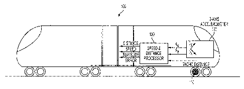
Figure 2 is a diagrammatical representation of a train acceleration and grade
monitoring system incorporating a two-axis accelerometer of the present
invention.
DETAILED DESCRIPTION OF THE INVENTION
The present invention will be explained in further detail by making reference
to the
accompanying drawings, which do not limit the scope of the invention in any
way.
Turning now to Figure 1, this Figure depicts a vector representation of the
train
acceleration at with respect to a normal reference axis x-y. In the embodiment
of the present
invention, the two-axis accelerometer is mounted in a longitudinal plane, with
respect to the
train, and at an angle 8 with respect to the x-axis (i.e. horizontal). The y
axis denotes a
vertical reference while the x axis denotes a horizontal reference. It is
noted that the angle 8
of mounting can be at any point between 0° to 90°, but is
preferably within the range of 35°
to 55°, and most preferably at an angle of 45°.
When the train is accelerating/decelerating andlor is on a graded portion of
the track,
the two-axis accelerometer measures the train's acceleration/deceleration and
gravity g
components along both the ax and ay axis of the accelerometer, as shown in
Figure 1. Based
on these measurements, obtained from the two-axis accelerometer, both the
acceleration/deceleration at and the grade Y of the train can be calculated.
The equations that
can be used to perform these calculations are as follows:
(1) ar=axCOSCS-f-ay'~'.Jg2-(axsinfi-ayCOS~)2
2 = acct a~ sin ~ - ay - ~ - _~c
( ) Y g~a~cos~-aX~ 2
-3-

CA 02488004 2004-11-19
As shown in the above equations the acceleration a~ of the train is dependent
only on
actual measurements taken by the two-axis accelerometer measurements and known
constants, such as the mounting angle b and gravity g. Additionally, by using
the above
equations the current grade y can be dynamically measured.
Figure 2 depicts, train acceleration and grade monitoring system incorporating
a two-
axis accelerometer of the present invention, shown on a train 100. As
indicated above, the
system uses a two-axis accelerometer 120 which is mounted in a longitudinal
plane of the
train 100. The mounting of the two-axis accelerometer 120 is in accordance
with the required
mounting standards for the particular accelerometer 120 used, and preferably
should be in a
vertical orientation, as shown in Figure 2. An example of a two-axis
accelerometer which
can be used is the ADXL202 from Analog Devices.
In a preferred embodiment, the two-axis accelerometer 120 uses iMEMS
technology
to integrate two accelerometers which are positioned 90 degrees, with respect
to teach other,
and provides outputs proportional to the tilt of each of the integrated
accelerometers. The
1 S accelerometer 120 has a plurality of outputs to provide the needed data.
Two of the outputs,
one each fox the X and Y directions, are in PWM format, where the output has a
nominal
50% duty cycle for a 0 degree tilt. These outputs are used in a
microcontroller based system.
Two additional outputs, again one each for the X and Y directions, are in
analogue format,
providing a DC voltage which is proportional to the tilt.
As shown in Figure 2, the system for monitoring the train acceleration uses a
speed
and distance processor card 130 and two sensors, the two-axis accelerometer
120 and a
tachometer 110. The two-axis accelerometer 120 is mounted in a longitudinal
plane of the
-4-

CA 02488004 2004-11-19
train 100 with the Ox and Oy axis rotated, most preferably, at 45 degrees from
the horizontal
and vertical axis, respectively.
The two PWM outputs from the two-axis accelerometer 120 are coupled to the
processor card 130, and the processor card 130 determines, from these inputs,
the true
S acceleration of the train 100, eliminating the grade component. This
determination is made in
accordance with the previous discussion, regarding Figure 1.
Additionally, the processor card 130 receives a signal from the tachometer
110, which
can be a digital tachometer. The tachometer 110 is mounted on an axle or wheel
of the train
100. The tachometer 110 outputs a predefined number of pulses for each
complete rotation
of the axle, (or wheel depending on the configuration). Thus, the tachometer
110 provides
the information on the distance traveled by the train 100 under normal
conditions, i.e. when
the wheel-to-rail adhesion is sufficient and no slipping or sliding is
occurring.
With the above information, the processor card 130 determines the speed of the
train
and then differentiates the distance traveled in time, using the tachometer
110 input, and
integrates the acceleration in time, using the acceleration input from the
accelerometer 120.
Then, the two speed values (from each of the sensors 110 and 120) are
continuously cross-
compared to ensure that the two are in agreement, within a predetermined or
defined
tolerance. If the tolerance is exceeded (i.e. the difference in speed values
between the sensors
120 and 110 is too great) a slippage or sliding condition is detected and the
processor card
130 compensates the train's 100 dynamics values. Stated differently, when the
difference
between the values from the two sensors 110 and 120 is over a threshold the
card 130
determines that the train 100 is slipping or sliding, and then the card 130
corrects the dynamic
-S-

CA 02488004 2004-11-19
values (i.e. speed and distance traveled) of the train 100. This permits the
train's systems to
accurately monitor the train's progress and data during conditions or times
when the train 100
has lost adhesion with the rails.
It is noted that although the above embodiment is discussed within the context
of
monitoring the dynamic values of a train, it is understood and contemplated
that the above
described system can be used on additional modes of transportation, including
passenger
vehicles, freight vehicles and the like.
It is of course understood that departures can be made from the preferred
embodiments of the invention by those of ordinary skill in the art without
departing from the
spirit and scope of the invention that is limited only by the following
claims.
-6-

Representative Drawing
A single figure which represents the drawing illustrating the invention.
Administrative Status

2024-08-01:As part of the Next Generation Patents (NGP) transition, the Canadian Patents Database (CPD) now contains a more detailed Event History, which replicates the Event Log of our new back-office solution.

Please note that "Inactive:" events refers to events no longer in use in our new back-office solution.

For a clearer understanding of the status of the application/patent presented on this page, the site Disclaimer , as well as the definitions for Patent , Event History , Maintenance Fee  and Payment History  should be consulted.

Event History

Description Date
Application Not Reinstated by Deadline 2010-12-08
Inactive: Dead - No reply to s.30(2) Rules requisition 2010-12-08
Deemed Abandoned - Failure to Respond to Maintenance Fee Notice 2010-11-19
Inactive: Abandoned - No reply to s.30(2) Rules requisition 2009-12-08
Inactive: S.30(2) Rules - Examiner requisition 2009-06-08
Revocation of Agent Requirements Determined Compliant 2008-05-13
Inactive: Office letter 2008-05-13
Letter Sent 2008-05-13
Appointment of Agent Requirements Determined Compliant 2008-05-13
Revocation of Agent Request 2008-03-11
Appointment of Agent Request 2008-03-11
Inactive: Office letter 2007-11-07
Inactive: Adhoc Request Documented 2007-11-07
Appointment of Agent Request 2007-10-02
Revocation of Agent Request 2007-10-02
Letter Sent 2006-10-26
Request for Examination Requirements Determined Compliant 2006-10-05
All Requirements for Examination Determined Compliant 2006-10-05
Request for Examination Received 2006-10-05
Inactive: IPC from MCD 2006-03-12
Application Published (Open to Public Inspection) 2005-06-22
Inactive: Cover page published 2005-06-21
Inactive: First IPC assigned 2005-02-02
Inactive: IPC removed 2005-02-02
Inactive: IPC assigned 2005-01-28
Inactive: Filing certificate - No RFE (English) 2005-01-12
Filing Requirements Determined Compliant 2005-01-12
Letter Sent 2005-01-12
Application Received - Regular National 2005-01-12

Abandonment History

Abandonment Date Reason Reinstatement Date
2010-11-19

Maintenance Fee

The last payment was received on 2009-10-29

Note : If the full payment has not been received on or before the date indicated, a further fee may be required which may be one of the following

  • the reinstatement fee;
  • the late payment fee; or
  • additional fee to reverse deemed expiry.

Please refer to the CIPO Patent Fees web page to see all current fee amounts.

Fee History

Fee Type Anniversary Year Due Date Paid Date
Application fee - standard 2004-11-19
Registration of a document 2004-11-19
Request for examination - standard 2006-10-05
MF (application, 2nd anniv.) - standard 02 2006-11-20 2006-10-25
MF (application, 3rd anniv.) - standard 03 2007-11-19 2007-10-22
Registration of a document 2008-02-21
MF (application, 4th anniv.) - standard 04 2008-11-19 2008-10-20
MF (application, 5th anniv.) - standard 05 2009-11-19 2009-10-29
Owners on Record

Note: Records showing the ownership history in alphabetical order.

Current Owners on Record
THALES
Past Owners on Record
MIHAI LUNGU
Past Owners that do not appear in the "Owners on Record" listing will appear in other documentation within the application.
Documents

To view selected files, please enter reCAPTCHA code :


To view images, click a link in the Document Description column. To download the documents, select one or more checkboxes in the first column and then click the "Download Selected in PDF format (Zip Archive)" or the "Download Selected as Single PDF" button.

List of published and non-published patent-specific documents on the CPD .

If you have any difficulty accessing content, you can call the Client Service Centre at 1-866-997-1936 or send them an e-mail at CIPO Client Service Centre.


Document
Description 
Date
(yyyy-mm-dd) 
Number of pages   Size of Image (KB) 
Abstract 2004-11-19 1 17
Description 2004-11-19 6 229
Claims 2004-11-19 5 108
Drawings 2004-11-19 2 22
Representative drawing 2005-05-25 1 8
Cover Page 2005-06-06 1 37
Courtesy - Certificate of registration (related document(s)) 2005-01-12 1 105
Filing Certificate (English) 2005-01-12 1 158
Reminder of maintenance fee due 2006-07-20 1 110
Acknowledgement of Request for Examination 2006-10-26 1 176
Courtesy - Abandonment Letter (R30(2)) 2010-03-02 1 165
Courtesy - Abandonment Letter (Maintenance Fee) 2011-01-14 1 172
Correspondence 2007-10-02 3 78
Correspondence 2007-11-07 1 13
Correspondence 2008-03-11 3 82
Correspondence 2008-05-13 1 21