Language selection

Search

Patent 2488235 Summary

Third-party information liability

Some of the information on this Web page has been provided by external sources. The Government of Canada is not responsible for the accuracy, reliability or currency of the information supplied by external sources. Users wishing to rely upon this information should consult directly with the source of the information. Content provided by external sources is not subject to official languages, privacy and accessibility requirements.

Claims and Abstract availability

Any discrepancies in the text and image of the Claims and Abstract are due to differing posting times. Text of the Claims and Abstract are posted:

  • At the time the application is open to public inspection;
  • At the time of issue of the patent (grant).
(12) Patent Application: (11) CA 2488235
(54) English Title: FLAT-SURFACE QUICK COUPLING TUBES EXTENDING BETWEEN A PRESSURIZED FLUID USER DEVICE AND A FLUID FEEDING MEANS
(54) French Title: TUBES DE RACCORDEMENT RAPIDE A SURFACE PLANE INSTALLES ENTRE UN DISPOSITIF UTILISATEUR DE FLUIDE SOUS PRESSION ET UN DISPOSITIF D'ALIMENTATION EN FLUIDE
Status: Deemed Abandoned and Beyond the Period of Reinstatement - Pending Response to Notice of Disregarded Communication
Bibliographic Data
(51) International Patent Classification (IPC):
  • F16L 37/56 (2006.01)
  • F16L 37/10 (2006.01)
  • F16L 39/00 (2006.01)
(72) Inventors :
  • AROSIO, MASSIMO (Italy)
(73) Owners :
  • FASTER, S.P.A.
(71) Applicants :
  • FASTER, S.P.A. (Italy)
(74) Agent: GOWLING WLG (CANADA) LLP
(74) Associate agent:
(45) Issued:
(22) Filed Date: 2004-11-23
(41) Open to Public Inspection: 2005-06-02
Examination requested: 2005-04-11
Availability of licence: N/A
Dedicated to the Public: N/A
(25) Language of filing: English

Patent Cooperation Treaty (PCT): No

(30) Application Priority Data:
Application No. Country/Territory Date
MI2003 A 002348 (Italy) 2003-12-02

Abstracts

English Abstract


A flat-surface quick coupling for coupling tubes extending
between a pressurized fluid user device and fluid feeding means
comprises a quick coupling (2) female part (1) and a quick
coupling (2) male part (12), to which are coupled concentric
tubes for providing a delivery duct and a return duct for a
hydraulic fluid, the ducts delimited by the concentric tubes being
operatively coupled to a delivery duct, respectively a return duct,
made inside the quick coupling parts (1) and (12), said ducts,
upon assembling the female part (1) and male part (12) being
mutually operatively connected.


Claims

Note: Claims are shown in the official language in which they were submitted.

-9-
Claims
1. A flat-surface quick coupling for coupling tubes extending
between a pressurized fluid user device and a fluid feeding
means, characterized in that said quick coupling (2) comprises a
quick coupling female part (1) and a quick coupling male part
(12) to which are connected concentric tubes (5, 10, 15, 20) so
as to provide a hydraulic fluid delivery duct (6, 16) and a
hydraulic fluid return duct (11, 37), and that the ducts defined by
said concentric tubes (5, 10, 15; 20) are operatively coupled to a
fluid delivery duct (7) respectively a fluid return duct (17)
provided inside said female part (1) and male part (12) and that
said ducts (7, 17), upon assembling said male and female parts
(11, 12), are mutually operatively connected.
2. A flat-surface quick coupling according to claim 1,
characterized in that said male part (12) rotatively houses a ring
nut (21) adapted to be locked at an axial position thereof by a
resilient ring element (22), and that said ring-nut (21) comprises
a front inner thread (23) to be coupled with a thread (24) of said
female part (1).
3. A flat-surface quick coupling according to claim 1,
characterized in that said stem (25) operates as a guide element
for a movable tubular element (31) including a circumferential
enlarged portion (32) thereagainst abuts a spring (33)

-10-
encompassed, on a front side thereof, by a movable ring gear
(34), said ring gear (34) being brought into abutment with an
outer tubular body (36) of said female part (1).
4. A flat-surface quick coupling according to claim 1,
characterized in that said mate part (12) supports in an inside
thereof, through and enlarged portion (18), a locally fixed tubular
element (40) and that against said tubular element (40) abuts a
spring (41) thereagainst abuts an enlarged portion (42) of an
axially movable tubular element (43), which, on a front side
thereof, is encompassed by a spring (44) thereagainst a further
tubular element (45) bears.

Description

Note: Descriptions are shown in the official language in which they were submitted.


CA 02488235 2004-11-23
_1 _
Description of the industrial invention entitled: "Flat-surface quick
coupling tubes extending between a pressurized fluid user device
and a fluid feeding means".
Background of the invention
The present invention relates to a flat-surface quick coupling for
coupling tubes extending between a pressurized fluid user device
and a fluid feeding means.
Is already known in the prior art to use quick couplings for
coupling flexible hoses to an user device; such as an actuator
device provided in an agricultural apparatus or a civil building
apparatus, for example a grader or an excavator.
Actually, in these machines resilient tubes or hoses for supplying
through a delivery tube a hydraulic fluid, e.g. a highly pressurized
oil, to an user, such as a cylinder/piston unit or hydraulic motor,
are used.
To recover or return the hydraulic fluid from the user to the
pressure source, such as a pump, it is indispensable to also
provide a fluid return tube.
Thus, from the prior art is already known to use two separated
flexible tubes or hoses provided, at their end portions, with quick
couplings for coupling an user device t~ a pressure source.

CA 02488235 2004-11-23
-2-
It is moreover frequently necessary to disconnect the fluid
delivery tube and fluid return tube from a set user, for example to
replace an operating tool, or to carry out servicing operations to
said operating tool.
Considering that in the past it was conventional to use two
separated tubes having a delivery function, respectively a return
function, and considering that the coupling operations were to be
performed in dirty environments and, moreover, that the
pressurized fluid tube connecting operations were to be
performed with a comparatively high speed, the delivery tube
could be erroneously connected to a hydraulic fluid return fitting
or vice versa, with the risk of a failure of the auxiliary apparatus
or of irreparable damages.
Finally, a further drawback of prior quick coupling for coupling a
delivery tube separated from a return tube, was the necessity of
providing two pairs of quick couplings, thereby greatly increasing
the system cost.
Summary of the invention
The main object of the present invention is to overcome the
above mentioned drawbacks of the prior art, by allowing to use a
single, quick coupling, both for the pressurized fluid delivery line
and return line, while allowing a quick and simple coupling to be

CA 02488235 2004-11-23
-3-
obtained, while absolutely preventing any assembling errors in
resilient tube connecting operations from occurring.
The above object is achieved by a flat-surface quick coupling for
coupling tubes extending between a pressurized fluid user device
and a fluid feeding means, characterized in that to a female part
of the flat-surface quick coupling and a male part of said flat-
surface quick coupling are coupled mutually concentric tubes to
provide a hydraulic fluid delivery duct and a hydraulic fluid return
duct, and that the ducts delimited by said concentric tubes are
operatively coupled to a fluid delivery duct, respectively a fluid
return duct, said ducts being made inside said female quick
coupling part and male quick coupling part, and that said ducts,
upon assembling said quick coupling parts, are mutually
operatively connected.
Brief description of the drawings
The subject matter according to the present invention will be
disclosed in a more detailed manner hereinafter and illustrated
by an embodiment thereof, given only by way of an example, and
shown in the accompanying drawings, where:
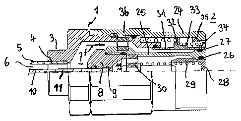
Figure 1 is a partially cross-sectioned view illustrating the female
part of the novel quick coupling;
Figure 2 is a partially cross-sectioned view illustrating the male

CA 02488235 2004-11-23
_4~
part of the novel quick coupling;
Figure 3 is a partially cross-sectioned view showing. the
components of the quick coupling at the start of the coupling
operation or step;
Figure 4 is a partially cross-sectioned view illustrating the quick
coupling components in an operatively connected condition; and
Figure 5 shows the quick coupling components at the end of the
connecting operation or step, with the flow ducts in an opened
condition to allow the hydraulis fluid to flow therethrough.
Description of the preferred embodiments
As shown in figure 1, the female part 1 of the flat-surface quick
coupling, generally indicated by 2, comprises an end fitting 3,
including an inner recess 4 for engaging therein an end portion of
a resilient tube or hose 5, defining a first annular duct 6.
The annular duct 6 is coupled to a further duct 7 formed inside
the body of the female part 1.
Inside said female part 1 is provided a ring-nut 8 defining a
recess 9 for engaging therein an end portion of a second resilient
tube or hose 10, leading to a duct 11 formed inside said female
part 1.
The fluid delivery and return tubes 5 and 10 are arranged
coaxially with respect to one another.

CA 02488235 2004-11-23
_5_
Figure 2 is a partially cross-sectioned view showing the male part
12 of the quick coupling, also indicated by the reference number
The quick coupling 2 comprises an end fitting 13 having an inner
recess 14 in which is engaged a flexible hose or tube 15 defining
a first hydraulic fluid flow duct 16 leading to a duct 17 delimited
by an insert 18, including a recess 19 therein is engaged an end
portion of a further flexible tube or hose 20 defining a further duct
37.
The fitting 12 rotatably houses a ring-nut 21 locked at an axial
position by a resilient ring element 22.
The rotary ring-nut 21 comprises, on a front side thereof, an inner
thread 23 allowing the two quick coupling parts 1, 12 to be
coupled, as the ring nut 21 is screwed on the outer thread 24 of
the female part 1.
The coupling steps for coupling the female part 1 and male part
12 are shown in figures 3, 4 and 5.
Figure 1 shows moreover that the female part 1 comprises a
locally fixed inner tubular stem 25, known per se in the prior art.
The tubular stem 25 operates as a separating element for the
ducts 7, 11. As shown, the stem 25 comprises a front enlarged
portion engaging an inner annular gasket 26, and an outer
annular gasket 27.

CA 02488235 2004-11-23
_6_
The inner annular gasket 26 is contacted by a tubular sliding ring
nut 28, urged by an urging preloaded spring 29 bearing against a
perforated bush 30, rigid with the end portion of the stem 25.
Against the outer annular gasket 27 is abutted a movable tubular
element 31, having a circumferential enlarged or bulged portion
32; thereagainst abuts a spring 33 which on a front side.thereof
is encompassed by a movable ring gear 34 which, at an
abutment point 35; abuts against an outer tubular body 36 of the
female part 1.
Figure 2 shows that the quick coupling male part 12 supports in
its inside, through the enlarged portion 18; a tubular element 40
which is locally fixed.
Against said tubular element 40 abuts a spring 41, thereagainst
abuts an enlarged portion 42 of an axially movable tubular
element 43 and which, on the front side thereof, is encompassed
by a spring 44 thereagainst a further tubular element 45 abuts.
Between the tubular element 43, the tubular element 45 and front
end portion of the body 46, a series of gaskets 47 and 48 are
provided.
The constructional elements 42, 43 and 45 are held in their
proper position by a central stem 50.
At the start of the coupling operation for coupling the quick
coupling parts 1 and 12, as shown in figure 3, the thread 23 of

CA 02488235 2004-11-23
-7-
the rotary ring nut 21 is brought into engagement with the outer
thread 24 of the tubular body 36. All the movable elements 34;
28 and 31 as well as 45 and 43, by way of an example, are yet in
their starting positions and the ducts 7, respectively 17, are shut-
off, and, accordingly, no delivery or return hydraulic fluid flow will
occur therethrough.
By further screwing on the ring nut 21 of the thread 24, the stem
25 causes the tubular body 45 to be backward displaced against
a spring 44, which will be consequently preloaded. In the
meanwhile; the tubular body 43 is also moved backward against
an urging spring 41 which is also preloaded.
This effect is obtained since the tubular elements 45 is driven by
the stem 25 included in the female part 1. Simultaneously the
tubular element 43, sliding along a stem 50 which is locally fixed
inside the male part 12, is axially displaced, thereby disengaging
the duct 9.
In figure 5, the female part 1 is fully coupled to the male part 12.
Owing to the operation of the locally fixed stem 25, the body 45
has been backward displaced against the urging spring 44 which
is preloaded and, owing to the operation of the body 46, also the
ring nut 34 and tubular body 31 will have been driven toward the
rear or back part of the female part 1, thereby disengaging or
clearing the duct 7 while allowing an unhindered hydraulic fluid

CA 02488235 2004-11-23
_ 8
flow through the duct 7, in the direction indicated by the arrows
{f) in figure 5.
Simultaneously, since also the duct 9 has been fully cleared, it
will be possible to provide return fluid, as shown by the arrows
(g) in figure 5.
Thus, a quick coupling 2 including the quick coupling parts 1 and
12 allows, for the first time, to use concentric tubes 5 and 10, and
thereby allowing a delivery flow and a return flow inside a single
quick coupling 2.

Representative Drawing
A single figure which represents the drawing illustrating the invention.
Administrative Status

2024-08-01:As part of the Next Generation Patents (NGP) transition, the Canadian Patents Database (CPD) now contains a more detailed Event History, which replicates the Event Log of our new back-office solution.

Please note that "Inactive:" events refers to events no longer in use in our new back-office solution.

For a clearer understanding of the status of the application/patent presented on this page, the site Disclaimer , as well as the definitions for Patent , Event History , Maintenance Fee  and Payment History  should be consulted.

Event History

Description Date
Time Limit for Reversal Expired 2009-11-23
Application Not Reinstated by Deadline 2009-11-23
Deemed Abandoned - Failure to Respond to Maintenance Fee Notice 2008-11-24
Amendment Received - Voluntary Amendment 2008-07-08
Inactive: S.30(2) Rules - Examiner requisition 2008-01-08
Inactive: IPC from MCD 2006-03-12
Application Published (Open to Public Inspection) 2005-06-02
Inactive: Cover page published 2005-06-01
Letter Sent 2005-05-16
Letter Sent 2005-05-03
Inactive: Single transfer 2005-04-11
Request for Examination Requirements Determined Compliant 2005-04-11
All Requirements for Examination Determined Compliant 2005-04-11
Request for Examination Received 2005-04-11
Inactive: First IPC assigned 2005-03-04
Inactive: IPC assigned 2005-03-04
Inactive: Courtesy letter - Evidence 2005-01-18
Inactive: Filing certificate - No RFE (English) 2005-01-13
Filing Requirements Determined Compliant 2005-01-13
Application Received - Regular National 2005-01-13

Abandonment History

Abandonment Date Reason Reinstatement Date
2008-11-24

Maintenance Fee

The last payment was received on 2007-11-09

Note : If the full payment has not been received on or before the date indicated, a further fee may be required which may be one of the following

  • the reinstatement fee;
  • the late payment fee; or
  • additional fee to reverse deemed expiry.

Please refer to the CIPO Patent Fees web page to see all current fee amounts.

Fee History

Fee Type Anniversary Year Due Date Paid Date
Application fee - standard 2004-11-23
Registration of a document 2005-04-11
Request for examination - standard 2005-04-11
MF (application, 2nd anniv.) - standard 02 2006-11-23 2006-11-23
MF (application, 3rd anniv.) - standard 03 2007-11-23 2007-11-09
Owners on Record

Note: Records showing the ownership history in alphabetical order.

Current Owners on Record
FASTER, S.P.A.
Past Owners on Record
MASSIMO AROSIO
Past Owners that do not appear in the "Owners on Record" listing will appear in other documentation within the application.
Documents

To view selected files, please enter reCAPTCHA code :


To view images, click a link in the Document Description column. To download the documents, select one or more checkboxes in the first column and then click the "Download Selected in PDF format (Zip Archive)" or the "Download Selected as Single PDF" button.

List of published and non-published patent-specific documents on the CPD .

If you have any difficulty accessing content, you can call the Client Service Centre at 1-866-997-1936 or send them an e-mail at CIPO Client Service Centre.


Document
Description 
Date
(yyyy-mm-dd) 
Number of pages   Size of Image (KB) 
Abstract 2004-11-23 1 30
Description 2004-11-23 8 335
Drawings 2004-11-23 5 227
Claims 2004-11-23 2 72
Representative drawing 2005-05-05 1 24
Cover Page 2005-05-17 1 54
Description 2008-07-08 8 325
Claims 2008-07-08 2 55
Filing Certificate (English) 2005-01-13 1 158
Acknowledgement of Request for Examination 2005-05-03 1 177
Courtesy - Certificate of registration (related document(s)) 2005-05-16 1 104
Reminder of maintenance fee due 2006-07-25 1 110
Courtesy - Abandonment Letter (Maintenance Fee) 2009-01-19 1 173
Correspondence 2005-01-13 1 28
Fees 2006-11-23 1 23
Fees 2007-11-09 1 20