Language selection

Search

Patent 2489079 Summary

Third-party information liability

Some of the information on this Web page has been provided by external sources. The Government of Canada is not responsible for the accuracy, reliability or currency of the information supplied by external sources. Users wishing to rely upon this information should consult directly with the source of the information. Content provided by external sources is not subject to official languages, privacy and accessibility requirements.

Claims and Abstract availability

Any discrepancies in the text and image of the Claims and Abstract are due to differing posting times. Text of the Claims and Abstract are posted:

  • At the time the application is open to public inspection;
  • At the time of issue of the patent (grant).
(12) Patent: (11) CA 2489079
(54) English Title: KNIFE GATE VALVE
(54) French Title: ROBINET-VANNE A GUILLOTINE
Status: Granted and Issued
Bibliographic Data
Abstracts

English Abstract

A valve for controlling the flow of materials is provided. The valve has a valve body having a bore, a guide attached to the valve body, a gate movable within the guide into and out of the bore, and an actuator for the gate, the bore of the valve body having a profile where the gate enters the bore, and the gate having a concave leading edge conforming to a profile of the bore. The valve may be us ed in throttling applications.


French Abstract

Valve servant à régler le débit d'une substance. Le corps de la valve comprend un alésage, un guide fixé au corps de la valve, une vanne mobile glissant dans le guide et se prolongeant dans l'alésage, de même qu'un actionneur pour la vanne. L'alésage du corps de la vanne est profilé à l'endroit ou la vanne pénètre dans l'alésage et celle-ci est munie d'un bord d'attaque concave dont le profil s'adapte à celui de l'alésage. La valve peut être utilisée pour régler un débit.

Claims

Note: Claims are shown in the official language in which they were submitted.

THE EMBODIMENTS OF THE INVENTION IN WHICH AN EXCLUSIVE PROPERTY OR
PRIVILEGE IS CLAIMED ARE DEFINED AS FOLLOWS:
1. A valve comprising:
a valve body having a bore;
a guide attached to the valve body;
a gate movable within the guide into the bore from a retracted position and
out of the
bore into the retracted position;
an actuator for the gate;
the bore of the valve body having sides and a bore width between the sides,
and the
bore having a profile where the gate enters the bore;
the gate having a concave leading edge conforming to the profile of the bore,
the
concave leading edge of the gate being flush with the profile of the bore
where the
gate enters the bore to eliminate exposed chest area when the gate is in the
retracted
position; and the gate having a gate width less than the bore width to produce
gaps
between the sides of the bore and the gate when the gate is extended into the
bore.
2. The valve of claim 1, where the gate is a knife gate.
3. The valve of claim 1 where the valve body further comprises retainer rings
and a valve
body bore liner.
4. The valve of claim 3 where the retainer rings and valve body bore liner are
replaceable.
5. The valve of claim 1, where the valve body further comprises an insert, the
insert creating
an obstruction in the bore.

6
6. The valve of claim 5, where the insert is V-shaped.
7. The valve of claim 1 in which:
the bore is circular and has a diameter;
the knife gate has parallel sides separated by the gate width;
the gate width is less than the diameter of the bore; and
the leading edge of the gate has a leading edge diameter equal to the diameter
of the bore.
8. A knife gate valve comprising:
a valve body having a bore;
a guide attached to the valve body;
a gate movable within the guide into the bore from a retracted position and
out of the
bore into the retracted position;
an actuator for the gate;
the bore of the valve body having sides and a bore width between the sides,
and the
bore having a profile where the gate enters the bore;
the gate having a recessed leading edge conforming to the profile of the bore,
the
recessed leading edge of the gate being flush with the profile of the bore
where the
gate enters the bore to eliminate exposed chest area when the gate is in the
retracted
position; and the gate having a gate width less than the bore width to produce
gaps
between the sides of the bore and the gate when the gate is extended into the
bore.
9. The knife gate valve of claim 8 in which:
the bore is circular and has a diameter;
the knife gate has parallel sides separated by the gate width;
the gate width is less than the diameter of the bore; and
the leading edge of the gate has a leading edge diameter equal to the diameter
of the bore.

Description

Note: Descriptions are shown in the official language in which they were submitted.


CA 02489079 2010-02-05
KNIFE GATE VALVE
BACKGROUND OF THE INVENTION
001 Gate valves are commonly used in the mining, pulp and paper, and food
handling
industries, among others. As known in the art, the gate moves linearly,
perpendicular to the
direction of flow. Typically, gate valves are used in a fully opened or fully
closed position, and
generally considered not suitable for throttling applications. In order to
seat properly when fully
closed, the typical gate valve is shaped to occupy all or substantially all of
the bore. While this
provides for robust sealing, the shape of the gate also has its disadvantages.
002 In a fully open position, areas within the bonnet or guide of a typical
gate valve, known
in the art as the chest area, may be exposed to flowing materials. When used
in higher flow
applications, this flow can have a detrimental effect on the integrity of the
valve. Materials can
also get clogged within the chest area of the valve body and the guide. Even
if the chest area
could be suitably sealed off, the traditional shape of the gate may create
flow characteristics not
desirable for throttling applications.
SUMMARY OF THE INVENTION
003 The present invention provides a gate valve for use in throttling
applications.
004 The gate valve in one embodiment comprises a valve body having a bore, a
guide
attached to the valve body, a gate movable within the guide into the bore from
a retracted
position and out of the bore into the retracted position; an actuator for the
gate; the bore of the
valve body having sides and a bore width between the sides, and the bore
having a profile where
the gate enters the bore; the gate having a concave leading edge conforming to
the profile of the
bore, the concave leading edge of the gate being flush with the profile of the
bore where the gate
enters the bore to eliminate exposed chest area when the gate is in the
retracted position; and the
gate having a gate width less than the bore width to produce gaps between the
sides of the bore
and the gate when the gate is extended into the bore.

CA 02489079 2004-12-21
2
BRIEF DESCRIPTION OF THE FIGURES
005 Preferred embodiments of the invention will now be described with
reference to the
figures, in which like reference characters denote like elements, by way of
example, and in
which:
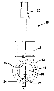
Fig. 1 is a front view of one embodiment of the valve;
Fig. 2 is a cross-section of the valve taken along line A of Fig. 1;
Fig. 3 is a perspective view of the valve in Fig. 1;
Fig. 4 is a front view of an alternative embodiment of the valve;
Fig. 5 is a rear view of the valve in Fig. 4;
Fig. 6 is a cross-section of the valve taken along line A of Fig. 4; and
Fig. 7 is a perspective view of tll valve ofFig. 4..
DETAILED DESCRIPTION OF PREFERRED EMBODIMENTS
006 In the claims, the word "comprising" is used in its inclusive sense and
does not
exclude other elements being present. The indefinite article "a" before a
claim feature does
not exclude more than one of the feature being present. The phrase "concave
leading edge"
refers to any shape of the leading edge such that if a straight line were
drawn from one side of
the end of the gate to the other side of the end of the gate, no part of the
leading edge would
touch any part of that line, and comprises any edge forming a recess.
007 Referring to Figs. 1 to 3, a valve 10 has a valve body 12 having a bore
14, a guide 16
attached to the valve body 12, a gate 18 movable within the guide 16 into and
out of the bore
14, and an actuator 20 for the gate 18. In a preferred embodiment, the bore 14
is circular.
The bore 14 has a profile 22, and the gate 18 has a concave leading edge 24
that conforms to
the profile 20 of the bore 14. The leading edge 24 is shaped such that when
the gate 18 is in a
fully open position, the leading edge 24 of the gate 18 is completely flush
with the profile 22
of the bore 14. This results in a complete elimination of any chest area
within the valve body
12 or the guide 16.

CA 02489079 2004-12-21
3
008 The valve gate 18 may be made of any suitable material for the application
The valve
gate may also be replaceable. In a preferred embodiment, the gate 18 is a
knife gate, but any
type of gate capable of linear movement perpendicular to the direction of flow
through the
valve 10 may be used. The gate 18 is movable incrementally between a fully
open position
where the gate 18 is retracted within the guide 16 and a fully lowered
position where the gate
18 acts in a throttling fashion within the bore 14, creating an obstruction
around which the
material flows. In a fully lowered position, the gate 18 will not seat in a
fashion causing a
total obstruction within the bore. The shape of the gate 18 inherently
requires that a gap 26
exist in the bore 14 at least between the leading edge 24 of the gate 18 and
the side of the bore
14 opposite the profile 22. The gap 26 may also occur between the sides of the
gate 18 and
the sides of the bore 14.
009 The valve body 12 may be unitary in construction, or it may have
replaceable parts.
The valve body 12 may have replaceable retainer rings 28. The retainer rings
28 may be
made of any suitable material for the application. The retainer rings 28 would
be installed in
conventional fashion using seals known in the art. The valve body 12 may also
have a
replaceable valve body bore liner 30 made of any suitable material for the
application
010 The actuator 20 may be of any type suitable for the purpose, including
handwheels,
chainwheels, bevel gears, levers, cylinders and electric motors. In a
preferred embodiment,
the actuator 20 uses a cylinder.
Ol l In an alternative embodiment, as shown in Figs. 4 to 7, the valve 40
incorporates a V-
shape in the valve body 12. The V-shape may be formed with the use of a V-
shaped insert 42.
All other parts are the same between the valve 10 and the valve 40. The V-
shaped insert 42
may be made of any suitable material for the application. The V-shaped insert
42 may be
replaceable. When the gate 18 of valve 40 is raised in a fully open position,
the V-shaped
insert 42 creates an initial obstruction which constricts the flow of material
passing through
the bore 14. As the gate 18 is lowered, the V-shaped insert 42 prevents
material from flowing

CA 02489079 2004-12-21
4
around the sides of gate 18. Also, the gap 26 between the side of the bore 14
opposite the
profile 22 and the leading edge 24 of the gate 18 is greatly reduced.
012 It should be understood that the V-shaped bore liner may be some other
shape than a
V, such as a modified V-shape, a [shape, a diamond, a rectangle, semi-circles
with parallel
sides, or crescent-shaped, depending on the degree of initial obstruction and
final obstruction
desired and the flow characteristics desired within the bore 14 of the valve
40.
013 Immaterial modifications may be made to the embodiments of the invention
described
here without departing from the invention.

Representative Drawing
A single figure which represents the drawing illustrating the invention.
Administrative Status

2024-08-01:As part of the Next Generation Patents (NGP) transition, the Canadian Patents Database (CPD) now contains a more detailed Event History, which replicates the Event Log of our new back-office solution.

Please note that "Inactive:" events refers to events no longer in use in our new back-office solution.

For a clearer understanding of the status of the application/patent presented on this page, the site Disclaimer , as well as the definitions for Patent , Event History , Maintenance Fee  and Payment History  should be consulted.

Event History

Description Date
Revocation of Agent Requirements Determined Compliant 2020-04-22
Appointment of Agent Requirements Determined Compliant 2020-04-22
Common Representative Appointed 2019-10-30
Grant by Issuance 2010-10-19
Inactive: Cover page published 2010-10-18
Inactive: Final fee received 2010-08-09
Pre-grant 2010-08-09
Letter Sent 2010-06-07
Notice of Allowance is Issued 2010-06-07
Inactive: Approved for allowance (AFA) 2010-05-13
Amendment Received - Voluntary Amendment 2010-02-05
Inactive: S.30(2) Rules - Examiner requisition 2009-08-06
Letter Sent 2008-02-19
Small Entity Declaration Request Received 2008-01-21
Letter Sent 2008-01-17
Inactive: Correspondence - Transfer 2007-12-20
Request for Examination Requirements Determined Compliant 2007-12-20
Small Entity Declaration Request Received 2007-12-20
All Requirements for Examination Determined Compliant 2007-12-20
Small Entity Declaration Determined Compliant 2007-12-20
Small Entity Declaration Request Received 2007-12-20
Request for Examination Received 2007-12-20
Application Published (Open to Public Inspection) 2006-06-21
Inactive: Cover page published 2006-06-20
Inactive: Office letter 2006-05-09
Inactive: Single transfer 2006-04-21
Inactive: First IPC assigned 2005-03-11
Inactive: Filing certificate - No RFE (English) 2005-01-19
Filing Requirements Determined Compliant 2005-01-19
Application Received - Regular National 2005-01-19

Abandonment History

There is no abandonment history.

Maintenance Fee

The last payment was received on 2009-12-17

Note : If the full payment has not been received on or before the date indicated, a further fee may be required which may be one of the following

  • the reinstatement fee;
  • the late payment fee; or
  • additional fee to reverse deemed expiry.

Please refer to the CIPO Patent Fees web page to see all current fee amounts.

Fee History

Fee Type Anniversary Year Due Date Paid Date
Application fee - small 2004-12-21
MF (application, 2nd anniv.) - small 02 2006-12-21 2006-12-06
Registration of a document 2007-12-20
MF (application, 3rd anniv.) - small 03 2007-12-21 2007-12-20
Request for examination - small 2007-12-20
MF (application, 4th anniv.) - small 04 2008-12-22 2008-10-24
MF (application, 5th anniv.) - small 05 2009-12-21 2009-12-17
Final fee - small 2010-08-09
MF (patent, 6th anniv.) - small 2010-12-21 2010-10-21
MF (patent, 7th anniv.) - small 2011-12-21 2011-12-13
MF (patent, 8th anniv.) - small 2012-12-21 2012-12-06
MF (patent, 9th anniv.) - small 2013-12-23 2013-12-18
MF (patent, 10th anniv.) - small 2014-12-22 2014-10-15
MF (patent, 11th anniv.) - small 2015-12-21 2015-10-02
MF (patent, 12th anniv.) - small 2016-12-21 2016-10-11
MF (patent, 13th anniv.) - small 2017-12-21 2017-11-24
MF (patent, 14th anniv.) - small 2018-12-21 2018-10-31
MF (patent, 15th anniv.) - small 2019-12-23 2019-11-22
MF (patent, 16th anniv.) - small 2020-12-21 2020-12-02
MF (patent, 17th anniv.) - small 2021-12-21 2021-10-15
MF (patent, 18th anniv.) - small 2022-12-21 2022-10-13
MF (patent, 19th anniv.) - small 2023-12-21 2023-10-30
Owners on Record

Note: Records showing the ownership history in alphabetical order.

Current Owners on Record
SUMMIT VALVE AND CONTROLS INC.
Past Owners on Record
MICHEL LEROUX
Past Owners that do not appear in the "Owners on Record" listing will appear in other documentation within the application.
Documents

To view selected files, please enter reCAPTCHA code :


To view images, click a link in the Document Description column. To download the documents, select one or more checkboxes in the first column and then click the "Download Selected in PDF format (Zip Archive)" or the "Download Selected as Single PDF" button.

List of published and non-published patent-specific documents on the CPD .

If you have any difficulty accessing content, you can call the Client Service Centre at 1-866-997-1936 or send them an e-mail at CIPO Client Service Centre.


Document
Description 
Date
(yyyy-mm-dd) 
Number of pages   Size of Image (KB) 
Description 2004-12-21 4 202
Abstract 2004-12-21 1 19
Drawings 2004-12-21 3 97
Claims 2004-12-21 2 48
Representative drawing 2006-05-25 1 7
Cover Page 2006-06-09 1 29
Description 2010-02-05 4 195
Claims 2010-02-05 2 62
Cover Page 2010-09-29 1 30
Filing Certificate (English) 2005-01-19 1 158
Reminder of maintenance fee due 2006-08-22 1 110
Courtesy - Certificate of registration (related document(s)) 2008-01-17 1 105
Acknowledgement of Request for Examination 2008-02-19 1 177
Commissioner's Notice - Application Found Allowable 2010-06-07 1 166
Maintenance fee payment 2023-10-30 1 26
Fees 2011-12-13 1 155
Fees 2012-12-06 1 155
Maintenance fee payment 2018-10-31 1 24
Correspondence 2005-01-19 1 72
Correspondence 2006-05-09 1 8
Correspondence 2006-05-09 1 19
Correspondence 2006-08-22 1 38
Fees 2006-12-06 1 26
Fees 2007-12-20 3 65
Correspondence 2007-12-20 3 66
Correspondence 2008-01-17 1 9
Correspondence 2008-02-19 1 85
Correspondence 2007-01-17 1 21
Correspondence 2007-12-20 3 81
Correspondence 2008-01-21 4 93
Fees 2008-10-24 1 28
Fees 2009-12-17 1 26
Correspondence 2010-06-07 1 88
Correspondence 2010-08-09 1 28
Fees 2010-10-21 1 199
Fees 2013-12-18 1 23
Fees 2014-10-15 1 24
Fees 2015-10-02 1 24
Fees 2016-10-11 1 25
Maintenance fee payment 2017-11-24 1 24
Maintenance fee payment 2019-11-22 1 25
Maintenance fee payment 2020-12-02 1 25
Maintenance fee payment 2021-10-15 1 25
Maintenance fee payment 2022-10-13 1 26