Language selection

Search

Patent 2490458 Summary

Third-party information liability

Some of the information on this Web page has been provided by external sources. The Government of Canada is not responsible for the accuracy, reliability or currency of the information supplied by external sources. Users wishing to rely upon this information should consult directly with the source of the information. Content provided by external sources is not subject to official languages, privacy and accessibility requirements.

Claims and Abstract availability

Any discrepancies in the text and image of the Claims and Abstract are due to differing posting times. Text of the Claims and Abstract are posted:

  • At the time the application is open to public inspection;
  • At the time of issue of the patent (grant).
(12) Patent: (11) CA 2490458
(54) English Title: EXTENDED RANGE LESS LETHAL PROJECTILE
(54) French Title: PROJECTILE A GRANDE PORTEE MOINS MEURTRIER
Status: Granted
Bibliographic Data
(51) International Patent Classification (IPC):
  • F42B 7/10 (2006.01)
  • F42B 10/38 (2006.01)
  • F42B 12/74 (2006.01)
(72) Inventors :
  • KEEGSTRA, NEIL (United States of America)
  • FRITZ, RANDY R. (United States of America)
  • FRITZ, ROBIN A. (United States of America)
  • KINCHIN, ANTHONY EDWARD (United Kingdom)
(73) Owners :
  • KEEGSTRA, NEIL (United States of America)
  • FRITZ, RANDY R. (United States of America)
  • FRITZ, ROBIN A. (United States of America)
  • KINCHIN, ANTHONY EDWARD (United Kingdom)
(71) Applicants :
  • KEEGSTRA, NEIL (United States of America)
  • FRITZ, RANDY R. (United States of America)
  • FRITZ, ROBIN A. (United States of America)
  • KINCHIN, ANTHONY EDWARD (United Kingdom)
(74) Agent: PIASETZKI NENNIGER KVAS LLP
(74) Associate agent:
(45) Issued: 2013-07-09
(22) Filed Date: 2004-12-17
(41) Open to Public Inspection: 2005-06-29
Examination requested: 2009-11-24
Availability of licence: N/A
(25) Language of filing: English

Patent Cooperation Treaty (PCT): No

(30) Application Priority Data:
Application No. Country/Territory Date
10/748,943 United States of America 2003-12-29

Abstracts

English Abstract

An extended range munition including a projectile having a generally cylindrical body includes a forward end and rearward end. The forward end includes a protruding member extending therefrom, thereby increasing the weight of said body and said forward. end. The body is formed of a non-metallic material having a durometer hardness less than conventional metallic projectile.


French Abstract

Une munition à grande portée comprenant un projectile dont le corps est généralement cylindrique comprend une extrémité avant et une extrémité arrière. L'extrémité avant comprend un élément en saillie qui s'étend à partir de l'extrémité avant, ce qui augmente ainsi le poids dudit corps et de ladite extrémité avant. Le corps est formé d'un matériau non métallique qui affiche une dureté mesurée au duromètre inférieure à celle d'un projectile métallique ordinaire.

Claims

Note: Claims are shown in the official language in which they were submitted.


THE EMBODIMENTS OF THE INVENTION IN WHICH AN EXCLUSIVE
PROPERTY OR PRIVILEGE IS CLAIMED ARE DEFINED AS FOLLOWS:
1. A less-lethal shot gun round comprising:
a generally elongate tubular hull having a forward end and an opposed
rearward end, said hull including a roll crimp at said forward end thereof;
a base enclosing said rearward end of said hull;
a propellant contained within said base;
a wad sealably positioned in said hull adjacent said rearward end;
a penetration-resistant kinetic energy projectile carried in said hull, said
projectile being a generally cylindrical member having an outer cylindrical
wall, said
projectile having a rearward end and a forward end with a hollow cylindrical
bore
extending from said rearward end of said projectile and further including a
convex
solid head at said forward end of said projectile, such that the center of
mass of said
projectile is closer to said forward end of said projectile than to said
rearward end of
said projectile, thereby increasing the weight of said projectile at said
forward end of
said projectile, said forward end of said projectile defining a rim about said
convex
solid head; and
said rim supporting said roll crimp and configured to open said roll crimp
upon firing, said projectile being formed of a homogenous non-metallic
material
having a durometer hardness of between about 20 and 90.
2. The less-lethal shot gun round of claim 1, wherein said outer
cylindrical wall
is dimpled.
3. The less-lethal shot gun round of claim 1, wherein said projectile is
manufactured of material molded from the group consisting of rubber, foam and
plastic.
4. The less-lethal shot gun round of claim 1, wherein said non-metallic
material
has a mass that is less than that of conventional shot gun projectile
materials.
5. The less-lethal shot gun round of claim 1, wherein said non-metallic
material
has a density that is less than that of conventional shot gun projectile
materials.

8


6. The less-lethal shot gun round of claim 1, wherein said durometer
hardness is
less than that of conventional shot gun projectile materials.
9

Description

Note: Descriptions are shown in the official language in which they were submitted.


~i'CA 02490458 2004-12-17
EXTENDED RANGE LESS LETHAL PROJECTILE
FIELD OF THE INVENTION
[0001) The present invention relates generally to a munition designed to
impact a target
with low lethality. More particularly, the present invention relates to a less-
lethal projectile
having extended range capabilities:
BA~GROUND OF THE INVENTION
[0002] There is a well established need to pmvide a munition, having a
projectile which
can impact a target with a low likelihood of inflicting a lethal blow. The
need for such a
munition can be seen in numerous situations such as military and police
applications, self
defense and even animal control. A desirable, less-lethal munition would be
able to impart a
stopping or disabling force on the target.
[0003) The art includes numerous examples of various projectiles, which are
designed to
impact the target with a less lethal force. One type of shotgun round designed
for less lethal
applications includes substituting a conventional shot gun slug with a
flexible deformable sack
which may contain particulate matter. The sack is designed to deform upon
impact with the
target, imparting a blow without significant penetration. Examples of such
less lethal rounds are
shown in U.S. Patent Nos. 6,202,562 and 6,283,037.


~~~ CA 02-490458 2004-12-17
[0804] Other examples of less-lethal shot gun rounds include slugs
manufactured from
deformable materials, which deform or spread out upon impact, thereby reducing
incidences of
penetration upon impact. An example of such rounds are shown in U.S. Patent
Nos. 3,952,662
and 5,691,501. Additionally, other rounds include destructible slugs carrying
fluid or other
substances within. Recreational paint balls are an example of such
destructible projectiles and
which are shown for example in U.S. Patent Nos. 5;254,379 and 6,546,874.
[0005] Each of the projectiles of the prior art, which are designed to be less
lethal, suffer
~ ~m certain disadvantages. First, the projectile or slug itself is
complicated and expensive to
manufacture, as compared with traditional shot gun slugs. Second, many of the
known, less-
lethal rounds require use of specialized non-standard weapons. Lastly, most
of~the available shot
gun rounds are not accurate over an extended range. This greatly reduces the
effectiveness of the
round.
[0006] It is, therefore, desirable to provide a less-lethal munition
projectile which is easy
to manufacture and provides effective, less-lethal impact over an extended
range.
SUMMARY OF INVENTION
[0007] The present invention provides an extended range munition of low
lethality. The
munition includes a projectile having a generally cylindrical body with a
forward end and a
rearward end. The forward end includes an extending protruding member to
increase the weight
of the body at the forward end. The body is formed of a light weight low
durometer non-metallic
material wliich dissipates energy upon impact.
2
i:

CA 02490458 2004-12-17
. . . . _ l''
. ~
[0008] In a preferred embodiment the outer wall of the body may be dimpled.
Also the
rearward end of the body may include a hollow bore.
[0009] The present invention additionally provides a less-lethal shot gun
mend. The
round inchtdes a generally tubular hull having a forward end and an opposed
rearward end. A
base encloses the rearward end of the hull. A propellant is contained within
the base. A wad is
sealably positioned in the hull adjacent to rearward end. A projectile slug is
carried in the hull.
The slug is generally a cylindrical member, having an outer cylindrical wall.
The slug further
includes a solid head at a forward end of the cylindrical member, thereby
increasing the weight
of the slug at the forward end. The slug is foriried of nonmetallic material
having a durometer
hardness less than conventional shot gun slug materials
gg~F DESCRIPTION OF THE DRAWINGS
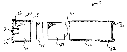
[0010] FIG. 1 is an exploded view partially in section of an extended range
munition
projectile of the present invention in the form of a shot gun round.
(0011] FIGS. 2-4 show a shot gun slug of the present invention in combination
with a
wad.
[0012) FIG. 5 shows an alternate embodiment of the shot gun slug of FIGS. 2-4.
3

' 1 _
CA 02490458 2004-12-17
DETAILED DESCRIPTION OF THE PREFERRED EMBODI1VVIENTS
[0013] The present invention directed to an extended range less-lethal
munition
projectile. The projectile of the present invention may be fired from various
weapons. The type
of weapon employed dictates the type of cartridge in which the projectile is
placed. For
simplicity of description the projectile will be described with respect to a
shot gun slug. It may
be appreciated, however, that the present invention is not limited thereto.
(0014] As is shown in FIG. 1, round 10 of the present invention may include a
base 12,
a wad 14 and a hull 16, all of generally conventional construction. Such
construction is shown
for example in U.S. Patent Nos. 6,202,562, issued March 20, 2001, to Brunn et
al and entitled,
"Methods of Preparing a Low Lethally Projectile for Flight'; and 6,546,874,
issued April 1S,
2003 to Vasel et al, entitled, "Non-lethal Projectile fo>~ Delivering an
Inhibiting Substance to a
Living Target," incorporated herein for all purposes.
[001 S) Base 12, which is generally formed of metallic material, preferably
brass, is a cup
shape member having an open upper end defining a base interior 20. Base
interior 20 supports a
propellant 22, which is generally an explosive charge. The base 12 also
supports at a lower end
24 ther~f a primer 26, which when struck, ignites the propellant. A wad 14
interposed between
base 12 and hull 16 which sealably contains propellant 22 in compression
sealing it from the
hull. As shown herein by way of example, wad 14 is a generally disk shape,
plastic member.
However, as is well known is the art and as is shown further herein below, wad
14 may take
various sizes, shapes and constructions, depending upon the application of the
round. Hull 16 is
an elongate, tubular member having an open end 30 adjacent base 12 and an
opposed crimped,
4
r

,,,~ . _., .
,CA 02490458 2004-12-17
i
closed end 32. Hull 16 of the present invention is typically formed of a
plastic material.
However, as is well known in the art, other materials and constructions for
hull 16 may also be
employed. In accordance with the present invention, hull 16 is designed to
support one or more
non lethal projectile shot gun slugs 40.
[0016] Referring more specifically to FIGS. 2-5, the projectile slug 40 of the
present
invention is shown. .Slug 40 is a generally, elongate cylindrical member
having a forward or
front end 42 and a rearward end 44. An outer cylindrical wall 46 extends
between the two ends.
The forward end 42 of slug 40 includes an outwardly extending dome shaped
element 48 about a
rim 49, so that slug 40 has the size and shape of a conventional lead shot gun
slug. The slug 40
may include a generally cylindrical bore 50, extending partially through the
body of slug 40, and
opening at end 44. The particular construction of the slug, shown in FIGS. 2
and 3, results in
the forward end 42 of the slug having an increased weight. Such weight
distribution is provided
in part by the hollow cylindrical bore adjacent end 44, as well as the dome
shaped element 48
extending from end 42. The weight distribution of the slug of the present
invention is such that
its weight is biased -forwardly. The nose forward aerodynamics (similar to a
badminton
shuttlecock) allows the slug to function as an accurate projectile when fired,
with little or no
distortion in its flight path over an extended range. While the hollow bore 50
helps in weight
distribution, it is contemplated that an aerodynamically stable slug may be
provided which is
completely solid, such as shown in FIG. 4. Slug 4' of FIG. 4 is identical to
slug 40 of FIGS. 2
and 3. However, the central bore 50 has been eliminated and the slug is
completely solid.

' ~,..,,~ CA 02490458 2004-12-17 .
s 'l
(0017] As shown in FIGS. 2-5, the large frontal area and the domed element 48
provides
a greater frontal surface area than a flat surface. This helps dissipate
energy on impact. In
situations where the hull 16 includes a roll crimp 33, the rim 49 serves to
open the roll crimp
upon firing.
[0018] FIGS. 2, 3 and 4 also show fiuther embodiments of the wad, which may be
employed by the slug of the present invention. Pressure wad 14' is of the type
more specifically
shown and described in U.S. Patent No. 6,502;516, issued fanuary 7, 2003,
entitled, "Sabot Shot
Gun Slug Assembly," which is incorporated by reference herein for all
purposes. The wad may
be attached to the slug as shown in FIG. 2, or may be a separate member, as
shown in FIGS. 3
and 4.
[0019] 'The less lethal shot gun slug of the present invention, while shaped
to mimic a
conventional lead shot gun slug of similar. size, is formed of a material
having low velocity and is
resistant to target penetration upon impact. Preferably, the slug of the
present invention may be
formed from a plastic material or other natural or synthetic materials having
a low hardness, such
as rubber, foam or a wide variety of plastics.
[0020] It is contemplated that preferable results are obtained with materials
having a
durometer hardness, ranging from about between 20 and 90. With this
construction and hardness
of material, the plug 40 of the present invention will impact the target with
low lethality and less
incidences of penetration.
6


- CA 02490458 2004-12-17
[0021] The present invention also contemplates modifying the outside
cylindrical surface
of slug 40.
[0022] Referring now to FIG. 5, slug 40" is shown. Slug 40" provides for a
dimpled
cylindrical wall 46". Dimples 49", which may be formed uniformly along the
outer surface of
the slug. The dimples 49" reduce the weight of the slug. Also the dimples 49"
reduce barrel
friction upon firing. This reduces the charge required to establish the
requisite velocity needed
for firing. ~ Such lower velocity is advantageous in firing less-lethal slugs.
[0023] Thus; the present invention provides an aerodynamic, extended range
projectile of
low lethality, which has a configuration which mimics a conventional slug of
similar size, so that
conventional weapons may be employed to fire the round.
7

Representative Drawing
A single figure which represents the drawing illustrating the invention.
Administrative Status

For a clearer understanding of the status of the application/patent presented on this page, the site Disclaimer , as well as the definitions for Patent , Administrative Status , Maintenance Fee  and Payment History  should be consulted.

Administrative Status

Title Date
Forecasted Issue Date 2013-07-09
(22) Filed 2004-12-17
(41) Open to Public Inspection 2005-06-29
Examination Requested 2009-11-24
(45) Issued 2013-07-09

Abandonment History

There is no abandonment history.

Maintenance Fee

Last Payment of $229.04 was received on 2022-12-08


 Upcoming maintenance fee amounts

Description Date Amount
Next Payment if small entity fee 2023-12-18 $253.00
Next Payment if standard fee 2023-12-18 $624.00

Note : If the full payment has not been received on or before the date indicated, a further fee may be required which may be one of the following

  • the reinstatement fee;
  • the late payment fee; or
  • additional fee to reverse deemed expiry.

Patent fees are adjusted on the 1st of January every year. The amounts above are the current amounts if received by December 31 of the current year.
Please refer to the CIPO Patent Fees web page to see all current fee amounts.

Payment History

Fee Type Anniversary Year Due Date Amount Paid Paid Date
Application Fee $200.00 2004-12-17
Maintenance Fee - Application - New Act 2 2006-12-18 $50.00 2006-12-13
Maintenance Fee - Application - New Act 3 2007-12-17 $50.00 2007-11-30
Maintenance Fee - Application - New Act 4 2008-12-17 $50.00 2008-12-12
Request for Examination $400.00 2009-11-24
Maintenance Fee - Application - New Act 5 2009-12-17 $100.00 2009-11-24
Maintenance Fee - Application - New Act 6 2010-12-17 $100.00 2010-12-15
Maintenance Fee - Application - New Act 7 2011-12-19 $100.00 2011-11-04
Maintenance Fee - Application - New Act 8 2012-12-17 $100.00 2012-12-17
Final Fee $150.00 2013-04-16
Maintenance Fee - Patent - New Act 9 2013-12-17 $100.00 2013-12-12
Maintenance Fee - Patent - New Act 10 2014-12-17 $125.00 2014-12-12
Maintenance Fee - Patent - New Act 11 2015-12-17 $125.00 2015-12-16
Maintenance Fee - Patent - New Act 12 2016-12-19 $125.00 2016-12-14
Maintenance Fee - Patent - New Act 13 2017-12-18 $125.00 2017-12-15
Maintenance Fee - Patent - New Act 14 2018-12-17 $125.00 2018-12-12
Maintenance Fee - Patent - New Act 15 2019-12-17 $225.00 2019-12-13
Maintenance Fee - Patent - New Act 16 2020-12-17 $225.00 2020-12-09
Maintenance Fee - Patent - New Act 17 2021-12-17 $229.50 2021-11-23
Maintenance Fee - Patent - New Act 18 2022-12-19 $229.04 2022-12-08
Owners on Record

Note: Records showing the ownership history in alphabetical order.

Current Owners on Record
KEEGSTRA, NEIL
FRITZ, RANDY R.
FRITZ, ROBIN A.
KINCHIN, ANTHONY EDWARD
Past Owners on Record
None
Past Owners that do not appear in the "Owners on Record" listing will appear in other documentation within the application.
Documents

To view selected files, please enter reCAPTCHA code :


To view images, click a link in the Document Description column. To download the documents, select one or more checkboxes in the first column and then click the "Download Selected in PDF format (Zip Archive)" or the "Download Selected as Single PDF" button.

List of published and non-published patent-specific documents on the CPD .

If you have any difficulty accessing content, you can call the Client Service Centre at 1-866-997-1936 or send them an e-mail at CIPO Client Service Centre.


Document
Description 
Date
(yyyy-mm-dd) 
Number of pages   Size of Image (KB) 
Maintenance Fee Payment 2019-12-13 1 33
Cover Page 2005-06-15 1 31
Maintenance Fee Payment 2020-12-09 1 33
Maintenance Fee Payment 2021-11-23 1 33
Maintenance Fee Payment 2022-12-08 1 33
Abstract 2004-12-17 1 15
Description 2004-12-17 7 272
Claims 2004-12-17 3 72
Drawings 2004-12-17 3 36
Representative Drawing 2005-06-01 1 6
Claims 2011-06-21 1 46
Claims 2012-05-23 2 51
Cover Page 2013-06-13 1 33
Prosecution-Amendment 2009-11-24 2 67
Fees 2010-12-15 2 63
Correspondence 2005-01-31 1 26
Assignment 2004-12-17 3 84
Correspondence 2006-06-02 5 172
Maintenance Fee Payment 2017-12-15 1 33
Correspondence 2006-08-16 1 13
Assignment 2004-12-17 4 123
Fees 2006-12-13 1 49
Correspondence 2007-11-30 6 148
Fees 2007-11-30 1 50
Fees 2008-12-12 1 47
Fees 2009-11-24 2 61
Prosecution-Amendment 2011-01-06 3 96
Prosecution-Amendment 2011-06-21 9 358
Fees 2011-11-04 2 64
Fees 2012-12-17 2 62
Prosecution-Amendment 2012-02-28 2 49
Prosecution-Amendment 2012-05-23 7 245
Correspondence 2013-04-16 2 69
Fees 2013-12-12 2 67
Fees 2014-12-12 1 33
Fees 2015-12-16 1 33
Fees 2016-12-14 1 33