Language selection

Search

Patent 2490948 Summary

Third-party information liability

Some of the information on this Web page has been provided by external sources. The Government of Canada is not responsible for the accuracy, reliability or currency of the information supplied by external sources. Users wishing to rely upon this information should consult directly with the source of the information. Content provided by external sources is not subject to official languages, privacy and accessibility requirements.

Claims and Abstract availability

Any discrepancies in the text and image of the Claims and Abstract are due to differing posting times. Text of the Claims and Abstract are posted:

  • At the time the application is open to public inspection;
  • At the time of issue of the patent (grant).
(12) Patent Application: (11) CA 2490948
(54) English Title: CONTROLLER SUPERVISION FOR ACTIVE VIBRATION DAMPING OF ELEVATOR CARS
(54) French Title: CONTROLEUR DE SUPERVISION DE L'AMORTISSEMENT DES VIBRATIONS DES CABINES D'ASCENSEUR
Status: Deemed Abandoned and Beyond the Period of Reinstatement - Pending Response to Notice of Disregarded Communication
Bibliographic Data
(51) International Patent Classification (IPC):
  • B66B 5/00 (2006.01)
  • B66B 1/06 (2006.01)
  • B66B 1/34 (2006.01)
  • B66B 3/00 (2006.01)
  • B66B 7/02 (2006.01)
  • B66B 7/04 (2006.01)
  • B66B 11/02 (2006.01)
(72) Inventors :
  • HUSMANN, JOSEF (Switzerland)
  • CORTONA, ELENA (Switzerland)
(73) Owners :
  • INVENTIO AG
(71) Applicants :
  • INVENTIO AG (Switzerland)
(74) Agent: RICHES, MCKENZIE & HERBERT LLP
(74) Associate agent:
(45) Issued:
(22) Filed Date: 2004-12-20
(41) Open to Public Inspection: 2005-06-22
Examination requested: 2009-11-25
Availability of licence: N/A
Dedicated to the Public: N/A
(25) Language of filing: English

Patent Cooperation Treaty (PCT): No

(30) Application Priority Data:
Application No. Country/Territory Date
03 405919.6 (European Patent Office (EPO)) 2003-12-22

Abstracts

English Abstract


The present invention automatically detects the onset of instability of the
active ride
control system and activates to system shutdown if this happens. As an
elevator car (1) is
guided along rails (15) by guide elements (6), a plurality of sensors (11,12)
mounted on
the car (1) measure vibration transverse to a direction of travel. The signals
from the
sensors (11,12) are input to a controller (19) which in turn produces a
controller output
signal (F). This signal (F) is used to energise an actuator (10) positioned
between the car
(1) and the guide elements (6) and thereby dampen the vibrations acting on the
car (1).
As instability sets in, a controller signal (F a) increases. This controller
signal (F a) is
monitored by a comparator (28) such that the actuator (10) is deactivated if
the controller
signal (F a) becomes greater than a predetermined value (F a max)


Claims

Note: Claims are shown in the official language in which they were submitted.

-5-
Claims
1. An apparatus for damping vibrations of an elevator car, the elevator car
guided
along rails by guide elements, comprising:
a plurality of sensors mounted on the car for measuring vibrations
transverse to a direction of travel;
at least one actuator positioned between the car and the guide elements;
and a closed-loop feedback controller responsive to signals from the
sensors to produce a controller output signal (F) to energize the actuator
CHARACTERISED IN THAT the controller includes a comparator to temporarily
deactivate the actuator if a selected component (F a,F p,F) of the controller
signal
(F) is greater than a predetermined value thereby preventing the onset of
instability.
2. An apparatus according to claim 1, wherein the plurality of sensors
includes a
position sensor and an accelerometer, the controller comprises a position
controller and an acceleration controller responsive to the signals from the
position
sensor and accelerometer respectively, outputs (F p,F a) from the controllers
are
combined to provide the controller output signal (F).
3. An apparatus according to claim 2, wherein the selected component of the
controller signal (F) is an output (F a) from the acceleration controller.
4. An apparatus according to claim 3, wherein the output (F a) from the
acceleration
controller is passed through a root-mean-square determining unit and a maximum
value determined is input to the comparator.
5. An apparatus according to any one of claims 2 to 4 wherein the controller
further
comprises a limiter to restrict the output (F p) from the position controller
to a
maximal value (F p) dependent on the temperature of the actuator.
6. A method for reducing oscillations of an elevator car, the elevator car
guided along
rails by guide elements, comprising the steps of:
measuring oscillations of the car transverse to a direction of travel; and

-6-
providing a control signal (F) for energising at least one actuator positioned
between the car and the guide elements in response to the measured
oscillations
CHARACTERISED BY
deactivating the actuator if a component of the control signal (F) is greater
than a
predetermined value and thereby preventing the onset of instability.
7. A method according to claim 6, wherein the step of measuring oscillations
includes
measuring a position and an acceleration of the car and the step of
deactivating
the actuator occurs if an acceleration component (F a) of the control signal
(F) is
greater than the predetermined value (F a max).
8. A method according to claim 7 further comprising the step of restricting a
position
component (F p) of the control signal (F) to a maximal value (F pL) depending
on the
temperature of the actuator.

Description

Note: Descriptions are shown in the official language in which they were submitted.


CA 02490948 2004-12-20
IP 1496
Controller Supervision for Active Vibration Damping of Elevator Cars
The present invention relates to a method and apparatus for detecting
instability of a
controller used to actively dampen vibrations on an elevator car in an
elevator installation.
EP-B-0731051 describes an elevator installation in which the ride quality is
actively
controlled using a plurality of electromagnetic linear actuators. Such a
system in
commonly referred to as an active ride control system. As an elevator car
travels along
guide rails provided in a hoistway, sensors mounted on the car measure the
vibrations
occurring transverse to the direction of travel. Signals from the sensors are
input to a
controller which computes the activation current required to suppress the
sensed
vibrations for each linear actuator. These activation currents are supplied to
the linear
actuators which actively dampen the vibrations and thereby the ride quality
for
passengers traveling within the car is enhanced.
The controller comprises a position controller with position feedback and an
acceleration
controller with acceleration feedback. The position controller is rather slow
and its output
is limited to a level so as not to cause overheating of the actuators. This
procedure is
described further in our co-pending Application entitled "Thermal Protection
of
2o Electromagnetic Motors". The output from the acceleration controller,
however, is not
restricted and can produce large amplitude, resonance forces at the actuators.
All closed loop controllers can become unstable if feedback gain is too high.
Indeed, the
acceleration controller can become unstable very easily since the feedback
gain margin
that leads to stability can be as low as a factor of two. Hence, simple
hardware failures or
software errors can easily cause instability of the acceleration controller.
An unstable
situation would not necessarily harm the safety of any passengers traveling in
the
elevator car, but undoubtedly causes a considerable amount of discomfort for
them. Since
the active ride control system is solely designed to improve passenger
comfort, an
3o unstable and vibrating system would therefore defeat the purpose of, and
completely
undermine user confidence in, the active ride control system.
Accordingly, the objective of the present invention is to detect instability
of the alive ride
control system and to shut the system down if this happens. Although the
vibration level

CA 02490948 2004-12-20
IP 9496
_2_
will rise, it will not approach the level inherent in the unstable active ride
control system.
The objective is met by providing an apparatus and method according to the
appended
claims.
By way of example only, a preferred embodiment of the present invention will
be
described in detail with reference to the accompanying drawings, of which:
FIG. 1 is a schematic representation of an elevator car traveling along guide
rails, the car
incorporating linear actuators to suppress vibration of the car; and
0
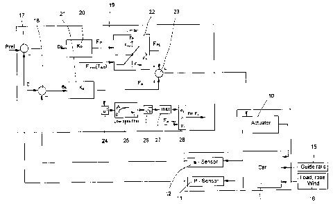
FIG. 2 shows a signal flow scheme of the active ride control system for the
elevator
installation of FIG. 1 incorporating instability detection according to the
present invention.
FIG. 1 is a schematic illustration of an elevator installation incorporating
an active ride
~5 control system according to the EP-B-0731051. An elevator car 1 is guided
by roller guide
assemblies 5 along rails 15 mounted in a shaft (not shown). Car 1 is suspended
elastically
in a car frame 3 for passive oscillation damping. The passive oscillation
damping is
performed by several rubber springs 4, which are designed to be relatively
stiff in order to
isolate sound or vibrations having a frequency higher than 50Hz.
The roller guide assemblies 5 are laterally mounted above and below car frame
3. Each
assembly 5 includes a mounting bracket and three rollers 6 carried on levers 7
which are
pivotally connected to the bracket. Two of the rollers 6 are arranged
laterally to engage
opposing sides of the guide rail 15. The levers 7 carrying these two lateral
rollers 6 are
interconnected by a linkage 9 to ensure synchronous movement. The remaining,
middle
roller 6 is arranged to engage with a distal end of the guide rail 15. Each of
the levers 7 is
biased by a contact pressure spring 8 towards the guide rail 15. This spring
biasing of the
levers 7, and thereby the respective rollers 6, is a conventional method of
passively
dampening vibrations.
Each roller guide assembly 5 further includes two electrical actuators 10
disposed to
actively move the middle lever 7 in the y direction and the two
interconnected, lateral
levers 7 in the x direction, respectively.

CA 02490948 2004-12-20
IP 7496
-3-
Unevenness in rails 15, lateral components of traction forces originated from
the traction
cables, positional changes of the load during travel and aerodynamic forces
cause
oscillations of car frame 3 and car 1, and thus impair travel comfort. Such
oscillations of
the car 1 are to be reduced. Two position sensors 11 per roller guide assembly
5
continually monitor the position of the middle lever 7 and the position of the
interconnected lateral levers 7, respectively. Furthermore, accelerometers 12
measure
transverse oscillations or accelerations acting on car frame 3.
The signals derived from the positions sensors il and accelerometers 12 are
fed into a
1o controller box 14 mounted on top of the car 1. The controller box 14
contains the power
electronics necessary to drive the actuators 10 and the closed loop feedback
controller 19
processing the signals from the sensors 11 and 12 to operate the actuators 10
in
directions such to oppose the sensed oscillations. Thereby, damping of the
oscillations
acting on frame 3 and car 1 is achieved. Oscillations are reduced to the
extent that they
are imperceptible to the elevator passenger.
FIG. 2 shows a signal flow diagram of the active ride control system for the
elevator
installation of FIG. 1 incorporating instability detection according to the
present invention.
External disturbances act of the car 1 and frame 3 as they travel along the
guide rails 15.
2o These external disturbances generally comprise high frequency vibrations
due mainly to
the unevenness of the guide rails 15 and relatively low frequency forces 16
produced by
asymmetrical loading of the car 1, lateral forces from the traction cable and
air
disturbance or wind forces. The disturbances are sensed by the positions
sensors 11 and
accelerometers 12 which produce signals that are fed into the controller 19.
In the controller 19, the sensed position signals are compared with reference
values P,~ at
summation point 17 to produce position error signals eP. The position error
signals eP are
then fed into a position feedback controller 20 which produces an output
signal Fp which
is restricted to a maximum absolute value Fm~ by a limiter 22. The value of F~
depends
on the temperature Tatt of the electrical actuators 10 and on their ability to
endure
thermal stress. This temperature limitation is fully described in our co-
pending Application
"Thermal Protection of Electromagnetic Motors". The output Fps from the
limiter 22 is fed
into summation point 23.

CA 02490948 2004-12-20
IP 1496
-4-
The signals from the accelerometers 12 are inverted at a summation point 18
and fed into
an acceleration feedback controller 21 as acceleration error signals ea. The
output Fa from
the acceleration controller 21 is combined with the output FPS from the
limiter 22 at
summation point 23. The resulting output control signal F is used as the input
for a power
amplifier (not shown) to produce current for the actuators 10 to counteract
the
disturbance forces and thus reduce vibrations on the car 1.
The output Fa of the acceleration controller 21 contains a broad band of
frequencies and
the amplitude of the higher frequency signals can be relative large. To detect
instability it
o is not sufficient to look at the amplitude of the signal; time duration has
also to be
weighted. A good measurement of stability is the moving root mean square or
RMS value.
It is a measure for the energy or power that is contained in a signal and time
duration
weighting can be chosen freely. The moving RMS value can be compared with a
maximum admissible value and if it exceeds the admissible value an error flag
is set true.
~ 5 The error signal will then deactivate the active ride control system and
the elevator car
will continue its operation with passive vibration damping. Deactivate can
mean switch off
or to gradually reduce the current supplied to the actuator 10. In the present
embodiment
the output signal Fa of the acceleration controller is squared in block 24.
The squared
signal has always a positive sign. In block 25 the squared signal is filtered
through a first
20 order low pass filter. The time constant of the low pass filter has to be
defined by
knowledge of the system and based on experience. In block 26 the square root
of the
filtered signal is calculated. Since the signal is a vector signal, which
contains several
values, the maximum value is chosen in block 27 and therefore the output from
block 27
represents the signal with the largest RMS amplitude. It is compared against a
maximum
25 admissible value Fa maX in block 28. If the largest RMS signal is greater
than the admissible
value, an error flag Err Fa is set true and the active ride control system is
switched off.
The admissible value again is derived by knowledge of the system and based on
experience. The active ride control system is reactivated after a
predetermined time
period.
It will be appreciated that the guide assemblies 5 may incorporate guide shoes
rather
then rollers 6 to guide the car 1 along the guide rails 15.

Representative Drawing
A single figure which represents the drawing illustrating the invention.
Administrative Status

2024-08-01:As part of the Next Generation Patents (NGP) transition, the Canadian Patents Database (CPD) now contains a more detailed Event History, which replicates the Event Log of our new back-office solution.

Please note that "Inactive:" events refers to events no longer in use in our new back-office solution.

For a clearer understanding of the status of the application/patent presented on this page, the site Disclaimer , as well as the definitions for Patent , Event History , Maintenance Fee  and Payment History  should be consulted.

Event History

Description Date
Inactive: Dead - Final fee not paid 2013-04-24
Application Not Reinstated by Deadline 2013-04-24
Deemed Abandoned - Failure to Respond to Maintenance Fee Notice 2012-12-20
Deemed Abandoned - Conditions for Grant Determined Not Compliant 2012-04-24
Notice of Allowance is Issued 2011-10-24
Letter Sent 2011-10-24
Notice of Allowance is Issued 2011-10-24
Inactive: Approved for allowance (AFA) 2011-10-07
Amendment Received - Voluntary Amendment 2011-08-22
Inactive: S.30(2) Rules - Examiner requisition 2011-07-25
Letter Sent 2010-01-07
Request for Examination Received 2009-11-25
All Requirements for Examination Determined Compliant 2009-11-25
Request for Examination Requirements Determined Compliant 2009-11-25
Inactive: IPC from MCD 2006-03-12
Application Published (Open to Public Inspection) 2005-06-22
Inactive: Cover page published 2005-06-21
Inactive: IPC assigned 2005-04-20
Inactive: First IPC assigned 2005-04-20
Application Received - Regular National 2005-02-01
Inactive: Filing certificate - No RFE (English) 2005-02-01
Filing Requirements Determined Compliant 2005-02-01
Letter Sent 2005-02-01

Abandonment History

Abandonment Date Reason Reinstatement Date
2012-12-20
2012-04-24

Maintenance Fee

The last payment was received on 2011-11-24

Note : If the full payment has not been received on or before the date indicated, a further fee may be required which may be one of the following

  • the reinstatement fee;
  • the late payment fee; or
  • additional fee to reverse deemed expiry.

Please refer to the CIPO Patent Fees web page to see all current fee amounts.

Fee History

Fee Type Anniversary Year Due Date Paid Date
Application fee - standard 2004-12-20
Registration of a document 2004-12-20
MF (application, 2nd anniv.) - standard 02 2006-12-20 2006-11-29
MF (application, 3rd anniv.) - standard 03 2007-12-20 2007-11-30
MF (application, 4th anniv.) - standard 04 2008-12-22 2008-11-28
Request for examination - standard 2009-11-25
MF (application, 5th anniv.) - standard 05 2009-12-21 2009-11-27
MF (application, 6th anniv.) - standard 06 2010-12-20 2010-11-25
MF (application, 7th anniv.) - standard 07 2011-12-20 2011-11-24
Owners on Record

Note: Records showing the ownership history in alphabetical order.

Current Owners on Record
INVENTIO AG
Past Owners on Record
ELENA CORTONA
JOSEF HUSMANN
Past Owners that do not appear in the "Owners on Record" listing will appear in other documentation within the application.
Documents

To view selected files, please enter reCAPTCHA code :


To view images, click a link in the Document Description column. To download the documents, select one or more checkboxes in the first column and then click the "Download Selected in PDF format (Zip Archive)" or the "Download Selected as Single PDF" button.

List of published and non-published patent-specific documents on the CPD .

If you have any difficulty accessing content, you can call the Client Service Centre at 1-866-997-1936 or send them an e-mail at CIPO Client Service Centre.


Document
Description 
Date
(yyyy-mm-dd) 
Number of pages   Size of Image (KB) 
Description 2004-12-20 4 203
Abstract 2004-12-20 1 21
Claims 2004-12-20 2 61
Drawings 2004-12-20 2 37
Representative drawing 2005-05-25 1 10
Abstract 2005-06-09 1 21
Cover Page 2005-06-16 1 42
Description 2011-08-22 5 240
Claims 2011-08-22 2 52
Courtesy - Certificate of registration (related document(s)) 2005-02-01 1 105
Filing Certificate (English) 2005-02-01 1 158
Reminder of maintenance fee due 2006-08-22 1 110
Reminder - Request for Examination 2009-08-24 1 125
Acknowledgement of Request for Examination 2010-01-07 1 188
Commissioner's Notice - Application Found Allowable 2011-10-24 1 163
Courtesy - Abandonment Letter (NOA) 2012-07-17 1 164
Courtesy - Abandonment Letter (Maintenance Fee) 2013-02-14 1 173