Language selection

Search

Patent 2491264 Summary

Third-party information liability

Some of the information on this Web page has been provided by external sources. The Government of Canada is not responsible for the accuracy, reliability or currency of the information supplied by external sources. Users wishing to rely upon this information should consult directly with the source of the information. Content provided by external sources is not subject to official languages, privacy and accessibility requirements.

Claims and Abstract availability

Any discrepancies in the text and image of the Claims and Abstract are due to differing posting times. Text of the Claims and Abstract are posted:

  • At the time the application is open to public inspection;
  • At the time of issue of the patent (grant).
(12) Patent Application: (11) CA 2491264
(54) English Title: DEVICE FOR PRODUCING MULTILAYER BLOWN FILM
(54) French Title: DISPOSITIF DE PRODUCTION DE FILM TUBULAIRE COMPLEXE
Status: Deemed Abandoned and Beyond the Period of Reinstatement - Pending Response to Notice of Disregarded Communication
Bibliographic Data
(51) International Patent Classification (IPC):
  • B29C 49/04 (2006.01)
  • B29C 49/42 (2006.01)
  • C08J 5/18 (2006.01)
(72) Inventors :
  • HESSENBRUCH, ROLF (Germany)
(73) Owners :
  • KIEFEL EXTRUSION GMBH
(71) Applicants :
  • KIEFEL EXTRUSION GMBH (Germany)
(74) Agent: SMART & BIGGAR LP
(74) Associate agent:
(45) Issued:
(22) Filed Date: 2004-12-21
(41) Open to Public Inspection: 2005-06-22
Examination requested: 2005-05-19
Availability of licence: N/A
Dedicated to the Public: N/A
(25) Language of filing: English

Patent Cooperation Treaty (PCT): No

(30) Application Priority Data:
Application No. Country/Territory Date
103 60 360.3 (Germany) 2003-12-22

Abstracts

English Abstract


Nine-layer blowing head for producing coextruded nine
layer blown film, in which the melt reunification is
chosen such that predominantly 3 melt streams are
reunited and the flowing together takes place in the
vicinity of the outlet region. The individual rings
forming the melt channel are mounted together to form a
number of groups and in this way allow rapid removal
and easier mounting.


Claims

Note: Claims are shown in the official language in which they were submitted.

-7-
CLAIMS
1. Method for producing multilayer films by the blown
film method, in which at least two melt streams are
respectively reunited at a combining location,
characterized in that, for producing nine-layer
films, at most three melt streams are reunited
respectively at a combining location.
2. Method according to Claim 1, characterized in that,
starting from nine individual streams, firstly
groups of three neighbouring melt streams are
combined to form three three-layer melt streams and
in that then the three three-layer melt streams are
combined.
3. Method according to Claim 1, characterized in that
initially three melt streams are combined to form a
three-layer melt stream, in that two individual
melt streams are combined with the three-layer melt
stream to form a five-layer melt stream, in that
groups of two individual melt streams are combined
to form two double melt streams and in that then
the five-layer melt stream is combined with the two
two-layer melt streams to form a nine-layer melt
stream.
4. Coextrusion blowing head for carrying out the
method according to one of Claims 1 to 3 with a
number of rings arranged concentrically in relation
to one another, which bound the channels for the
individual melt streams, characterized in that ten
concentric rings (11 to 18, 23, 24) are provided,
in that at least two rings (13, 15, 17) are
provided with flange-like attachments for
respectively receiving at least one ring (11, 12,

-8-
14, 18) and in that the supporting rings (13, 15,
17), supporting the at least one further ring, are
arranged on a base plate (25).
5. Coextrusion blowing head according to Claim 4,
characterized in that the respective combining
locations (6 to 10; 19 to 22) for combining melt
streams lie in the upper region of the blowing head
and the last combining location (10, 22) is
provided in the direct vicinity of the melt flow
outlet of the blowing head.

Description

Note: Descriptions are shown in the official language in which they were submitted.


CA 02491264 2004-12-21
w'
Kiefel Extrusion GmbH
Our ref: 221/K31/CA
DEVICE FOR PRODUCING MULTILAYER BLOWN
The invention relates to a device for producing nine-
layered film comprising different polymer layers which
are produced by the blown film method.
Multilayer films are produced from different polymers
to combine the different properties of the individual
polymers in one film. These properties are required
for the use of the films, for example in the case of
food packagings. Barrier properties, welding
characteristics and mechanical and thermal properties
can be optimized in this way. It is understandable
that, as the number of layers increases, so too do the
possibilities of achieving optimization. Furthermore,
commercial advantages can be achieved by the use of
plastics which are inexpensive and easy to process.
Films with more than 7 layers are usually produced in
blowing heads in which the individual layers are
distributed over the circumference by means of
horizontal melt distributions (known as pancake design)
(Figure 1). The individual layers are fed at offset
heights to a central melt channel. On account of the
individual layer distributions, arranged one above the
other, such a blowing head is of a relatively great
height, and consequently the central joint flow channel
is also very long. This in turn leads to disadvantages
from aspects of process technology with regard to the
use of different melt viscosities and makes it more
difficult to achieve greatly differing layer
thicknesses with good layer thickness tolerances. In
addition to this there are disadvantages caused by the
very great forces occurring in the distribution of the
melts over the circumference.

CA 02491264 2004-12-21
- 2 -
The purpose of the present invention is to avoid these
disadvantages and to develop a method an a blowing head
with conventional passage of the melt. This object is
achieved by the features of Claims 1 and 4.
Developments can be found in Claims 2,3 and 5.
Important in this respect is the passage of the melt in
separate streams and a reunification of the melt which
allows a high degree of flexibility with regard to the
plastics used and the layer thicknesses. For this
purpose, it is necessary to keep the individual melt
streams separate for as long as possible, to limit the
number of different melt streams that are reunited and
to locate where they are reunited as close as possible
to the outlet region of the blowing head. It is also
important that the reunification of the melt streams
takes place in such a way that similar materials are
grouped together first and these groups of melts are
meaningfully combined with the other, likewise grouped,
melt streams.
The invention is described in more detail on the basis
of exemplary embodiments shown in the accompanying
drawings, in which:
Figure 1 shows a blowing head with horizontal melt
pre-distribution (pancake design)
Figure 2 shows a blowing head with 2 points of melt
reunification
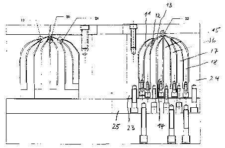
Figure 3 shows a blowing head according to this
invention with 3 triple and 2 double melt
reunifications
Figure 4 shows another blowing head according to this
invention with 4 triple points of melt
reunification.
Figure 1 shows a blowing head with horizontal melt
distribution over the circumference 1 and the
reunification of the individual layers in the joint

CA 02491264 2004-12-21
- 3 -
channel 2, the layers of melt being reunited at offset
heights. The type of construction results in very long
channels in which the individual layers are reunited.
This gives rise to problems in the selection of the
materials used, since only a limited spectrum of
viscosities can be used to avoid instances of mixing or
flow irregularities. Furthermore, with the long
channel 2, instances of separation or changes of
tolerances can occur. Furthermore, the forces caused
by the melt pre-distribution 1 are very great and can
only be handled with great effort.
These disadvantages are avoided by blowing heads with
conventional passage of melt in which the individual
melt streams are reunited not far from the outlet.
However, these blowing heads are known only in the form
of blowing heads with a maximum of 7 layers, since it
has appeared that, with more than 7 layers, the number
of layers and the reunification of the individual
layers cannot be handled.
Figure 2 shows a blowing head with 9 layers, in which
it is attempted to reunite as many layers as possible
at one point. In the present case, five layers are
reunited at the point 3. Since the melts consist of
different types of raw material, for example adhesion
promoters and barrier materials, this solution cannot
be used without difficulties, since turbulences can
occur at the combining point. At the 2nd combining
point 4, 5 layers are again reunited, specifically four
layers obliquely from below and one layer vertically
from below, comprising the layers reunited at point 3,
as a result of which the problems mentioned above can
occur here too. Furthermore, Figure 2 shows that the
rings 5 forming the melt channels are all mounted on
the base plate 5A and, as a result, the tolerances of
the individual rings 5 are added together and the
maintenance of close tolerances is not ensured.
Moreover, mounting, and in particular removal, is very

CA 02491264 2004-12-21
- 4 -
time-consuming and can make disassembly into the
individual parts impossible, since removal has to take
place at temperatures at which all the polymers still
have to be in the plastic state, but, because of the
great amount of time required, the individual parts
cool down and the polymers solidify, and consequently
prevent removal.
The present invention solves these problems. Figure 3
shows a nine-layer blowing head in which the individual
layers are reunited in such a way that never more than
3 melt channels are combined. At the point 6, the 3
inner layers are reunited. Since these materials
normally come from the same family of barrier
materials, this reunification is unproblematical. This
melt composite is combined at the point 7 with the next
two layers, normally the adhesion promoters, i.e. here,
too, 3 laminar-flowing melt streams are combined,
specifically two flows from obliquely below and one
flow vertically from below, making up the three flows
reunited at point 6. This melt composite, likewise as
a laminar flow, in turn meets the melt combination 10
comprising the two inner layers and the two outer
layers, which have previously been combined at the
points 8 and 9. The individual rings from which the
melt channels are formed are already pre-mounted, and
so make easier mounting and removal possible. For
instance, the inner rings 11 and 12 are mounted on the
supporting ring 13, the rings 14 and 16 are mounted on
the supporting ring 15 and the ring 18 is mounted on
the supporting ring 17. In respect of mounting and
removal, the 3 groups of supporting rings 13, 15 and 17
for example are removed and can be simultaneously
disassembled at separate locations without the risk of
solidification existing. In this blowing head shown in
Figure 3, the inner ring is designated 23 and the
outermost ring is designated 24, while the bas plate on
which the supporting rings are fastened by means of
screws has the designation 25.

CA 02491264 2004-12-21
Shown in Figure 4 is another solution of a nine-layer
blowing head, which essentially meets the criteria of
the blowing head in Figure 3, but represents an even
better solution for the reunification of the melts. In
the case of this blowing head, the 9 layers are
immediately reunited by 3 layers respectively being
combined at the points 19, 20 and 21 to form a melt
composite and combined at a further combining point 22
to form the final composite. It is particularly
advantageous in the case of this solution that the
melts that are respectively combined belong to similar
types of polymer. At the point 19, the three outer
layers, which all come from the family of polyolefins
(PE and adhesion promoters), are combined. The same
applies at the combining point 21, at which 3
polyolefin layers likewise flow together. At the
combining point 20, finally, 3 polymers which belong to
the family of barrier materials (COPA, PA, EVOH) are
combined. These melt composites come together as
laminar flows at the combining point 22. A further
advantage of this solution is that all the layers flow
separately for a relatively long distance and only flow
together shortly before leaving the blowing head. This
avoids instances of mixing of the individual melts due
to turbulences which may arise if a number of melt
streams flow jointly over relatively long channels. In
the case of this solution, polymers which have very
different melt viscosities can also be used. Different
melt viscosities in turn also make very different layer
thicknesses possible. This contributes to an increase
in cost-effectiveness, since the layer thicknesses are
not determined by the structural design of the blowing
head but essentially by the requirements of the
packaging task. In this case too, the rings which form
the melt channels are pre-mounted on supporting rings
in order to exploit the advantages mentioned above. In
Figure 4, the same reference numbers have been used,
although the individual rings are not formed

CA 02491264 2004-12-21
- 6 -
identically to those according to Figure 3 in terms of
the formation of the combining locations. There are
also ten rings present here, some rings being formed as
supporting rings as in Figure 3, in order to be able to
combine groups of rings into mounting units, which are
then mounted on the base plate 25, thereby facilitating
mounting and removal.

Representative Drawing
A single figure which represents the drawing illustrating the invention.
Administrative Status

2024-08-01:As part of the Next Generation Patents (NGP) transition, the Canadian Patents Database (CPD) now contains a more detailed Event History, which replicates the Event Log of our new back-office solution.

Please note that "Inactive:" events refers to events no longer in use in our new back-office solution.

For a clearer understanding of the status of the application/patent presented on this page, the site Disclaimer , as well as the definitions for Patent , Event History , Maintenance Fee  and Payment History  should be consulted.

Event History

Description Date
Inactive: IPC deactivated 2011-07-29
Application Not Reinstated by Deadline 2010-09-03
Inactive: Dead - Final fee not paid 2010-09-03
Deemed Abandoned - Failure to Respond to Maintenance Fee Notice 2009-12-21
Deemed Abandoned - Conditions for Grant Determined Not Compliant 2009-09-03
Notice of Allowance is Issued 2009-03-03
Letter Sent 2009-03-03
Notice of Allowance is Issued 2009-03-03
Inactive: IPC removed 2009-02-23
Inactive: First IPC assigned 2009-02-23
Inactive: IPC removed 2009-02-23
Inactive: Approved for allowance (AFA) 2008-11-12
Amendment Received - Voluntary Amendment 2008-09-08
Amendment Received - Voluntary Amendment 2008-08-06
Inactive: S.30(2) Rules - Examiner requisition 2008-03-06
Inactive: S.29 Rules - Examiner requisition 2008-03-06
Inactive: IPC from MCD 2006-03-12
Application Published (Open to Public Inspection) 2005-06-22
Inactive: Cover page published 2005-06-21
Letter Sent 2005-05-30
Request for Examination Requirements Determined Compliant 2005-05-19
All Requirements for Examination Determined Compliant 2005-05-19
Request for Examination Received 2005-05-19
Inactive: IPC assigned 2005-03-08
Inactive: First IPC assigned 2005-03-08
Inactive: IPC assigned 2005-03-08
Inactive: IPC removed 2005-03-08
Inactive: IPC assigned 2005-03-08
Letter Sent 2005-03-04
Inactive: Single transfer 2005-02-08
Inactive: Courtesy letter - Evidence 2005-02-08
Application Received - Regular National 2005-02-02
Filing Requirements Determined Compliant 2005-02-02
Inactive: Filing certificate - No RFE (English) 2005-02-02
Amendment Received - Voluntary Amendment 2004-12-21

Abandonment History

Abandonment Date Reason Reinstatement Date
2009-12-21
2009-09-03

Maintenance Fee

The last payment was received on 2008-11-20

Note : If the full payment has not been received on or before the date indicated, a further fee may be required which may be one of the following

  • the reinstatement fee;
  • the late payment fee; or
  • additional fee to reverse deemed expiry.

Please refer to the CIPO Patent Fees web page to see all current fee amounts.

Fee History

Fee Type Anniversary Year Due Date Paid Date
Application fee - standard 2004-12-21
Registration of a document 2005-02-08
Request for examination - standard 2005-05-19
MF (application, 2nd anniv.) - standard 02 2006-12-21 2006-12-20
MF (application, 3rd anniv.) - standard 03 2007-12-21 2007-11-22
MF (application, 4th anniv.) - standard 04 2008-12-22 2008-11-20
Owners on Record

Note: Records showing the ownership history in alphabetical order.

Current Owners on Record
KIEFEL EXTRUSION GMBH
Past Owners on Record
ROLF HESSENBRUCH
Past Owners that do not appear in the "Owners on Record" listing will appear in other documentation within the application.
Documents

To view selected files, please enter reCAPTCHA code :


To view images, click a link in the Document Description column. To download the documents, select one or more checkboxes in the first column and then click the "Download Selected in PDF format (Zip Archive)" or the "Download Selected as Single PDF" button.

List of published and non-published patent-specific documents on the CPD .

If you have any difficulty accessing content, you can call the Client Service Centre at 1-866-997-1936 or send them an e-mail at CIPO Client Service Centre.


Document
Description 
Date
(yyyy-mm-dd) 
Number of pages   Size of Image (KB) 
Abstract 2004-12-21 1 13
Description 2004-12-21 6 268
Claims 2004-12-21 2 55
Drawings 2004-12-21 4 184
Representative drawing 2005-05-25 1 23
Cover Page 2005-06-09 1 49
Description 2008-08-06 7 281
Claims 2008-08-06 1 37
Filing Certificate (English) 2005-02-02 1 158
Courtesy - Certificate of registration (related document(s)) 2005-03-04 1 105
Acknowledgement of Request for Examination 2005-05-30 1 176
Reminder of maintenance fee due 2006-08-22 1 110
Commissioner's Notice - Application Found Allowable 2009-03-03 1 162
Courtesy - Abandonment Letter (NOA) 2009-11-26 1 164
Courtesy - Abandonment Letter (Maintenance Fee) 2010-02-15 1 171
Correspondence 2005-02-02 1 26