Note: Descriptions are shown in the official language in which they were submitted.
CA 02514664 2005-08-03
-1-
STAIR TREAD PROTECTION SYSTEM
FIELD OF THE INVENTION
[0001 ] This invention relates to a device for protecting stair treads and
a stair system using a tread protector device.
BACKGROUND OF THE INVENTION
[0002] Stairs such as those installed in residential homes can be made
of costly but decorative materials. For example, stairs can be made of
hardwood such as oak or cherry. A finished staircase is typically built in a
location remote from the site of final installation. Once built, the staircase
is
shipped to the installation location and then installed as required. The
staircase is generally installed prior to completion of construction of the
home
or other building, and is used during construction of the building to gain
access to upper floors.
[0003] A staircase is susceptible to damage during shipping,
installation, and use prior to completion of construction of the building in
which
the stairs are installed. The stair treads (the upper surfaces of the
horizontal
step portions of the staircase) are particularly susceptible to damage.
Workers using the stairs can damage the treads with work boots or by
embedding nails or other objects in the treads.
[0004] To help protect the stairs, it is known to cover the stairs with a
loose fitting plastic wrap. Such a wrap can help keep paint and other debris
off the stairs, but does not generally offer significant protection against
damage such as that which may be caused by impact to the stairs, or by
imbedding objects into the stairs. Securing a sheet of wood onto the upper
surface of the treads can improve protection, but this can be time-consuming,
costly, and, upon removal, can leave nail or staple marks in the finished
staircase.
CA 02514664 2005-08-03
_2_
SUMMARY OF THE INVENTION
[0005] It is an object of this invention to provide a method and
apparatus suitable for protecting stairs from certain types of damage. In
particular, this invention provides a protector device for stair treads that
can
be installed in a press-fit or snap-fit arrangement on the stairs, without
need
for using any nails, staples, or the like to secure the protector device to
the
stair treads. Moreover, the present invention provides a system for protecting
stairs including providing stairs with a first retaining element along the
underside of the tread nose, and a stair protector with a second retaining
element for engaging the first retaining element in snap-fit when the
protector
is installed on the stair.
[0006] According to a first aspect of the invention, a protector device for
protecting a stair tread has a base portion adapted to cover at least a
portion
of a stair tread and upon which a user can step. The base portion has a
forward edge adapted to be generally aligned with a forward edge of the stair
tread. The protector is further provided with a clip portion extending from
the
forward edge of the base portion and adapted to secure the protector device
to the stair tread.
[0007] The clip portion can have an offset arm extending from the
forward edge of the base portion, and a retaining member extending from the
offset arm, opposite the base portion. The retaining member can be movable
between open and closed positions, wherein in the closed position, the
retaining member is adapted to bear against the underside surface of the
tread and the clip portion exerts a clamping force across the thickness of the
tread. The retaining member can be biased toward the closed position. The
clip portion can have a generally C-shaped configuration.
[0008] According to a second aspect of the present invention, a system
for protecting stairs includes a stair tread in combination with a tread
protector
device. The protector device can have a tread connection element that can
be in the form of a tooth or barb for engaging the underside surface of a
tread.
CA 02514664 2005-08-03
-3-
The tread can have a protector device connection element for interengaging
with the tread connector element to enhance the attachment between the
protector device and the tread. The protector device connection element of
the tread can be in the form of a groove provided in the underside surface of
the tread and adapted to receive the tread connection element of the
protector device.
[0009] According to a third aspect of the present invention, a protector
device for protecting stair treads is provided with a template portion. The
template portion can facilitate the installation of staircase accessories,
such
as balusters for a handrail, to the treads. The template portion can include
template features such as holes, cut-outs, or a visible design punched or
pressed into the protector device.
BRIEF DESCRIPTION OF THE INVENTION
[0010] For a better understanding of the present invention and to show
more clearly how it would be carried into effect, reference will now be made
by way of example, to the accompanying drawings that show a preferred
embodiment of the present invention, and in which:
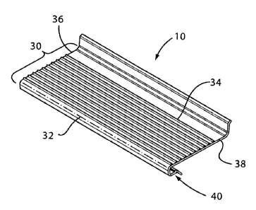
[0011] Figure 1 is a perspective view of the stair protector device of
Figure 1;
[0012] Figure 2 is a perspective view of a stair protector device shown
in combination with a staircase, in accordance with one embodiment of the
present invention;
[0013] Figure 3a is an enlarged side view of a portion of the
combination of Figure 1;
[0014] Figure 3b is a partially exploded side view of a portion of the
combination of Figure 1;
[0015] Figure 3c is a further enlarged side view of a portion of the
combination of Figure 3a;
CA 02514664 2005-08-03
-4-
[0016] Figure 4 is a perspective view of an alternate embodiment of a
staircase and a tread protector device according to the present invention;
[0017] Figure 5a is an exploded view of the staircase and protector
device of Figure 4;
[0018] Figure 5b is an enlarged view of a portion of the staircase and
protector device of Figure 5a;
[0019] Figures 6 and 7 are a perspective view and an enlarged portion
thereof, respectively, illustrating a further alternate embodiment of a
staircase
and a tread protector device according to the present invention; and
[0020] Figures 8 and 9 are side views in cross-section of alternative
embodiments of stair tread protector devices in accordance with the present
invention.
DETAILED DESCRIPTION OF THE INVENTION
[0021] A stair tread protector device 10 according to the present
invention is shown in Figure 1. Referring to Figure 2, a staircase 14 is
shown.
The staircase 14 can be, for example, a finished staircase built in a location
remote from the site of final installation. The staircase 14 typically
comprises
one or more treads 12 providing generally horizontal members upon which a
person can step when walking up or down the staircase 14. The staircase 14
can further be provided with risers 15 extending generally vertically between
successive treads 12 of the staircase 14. In Figure 2, a plurality of
protector
devices 10 are shown, with each one associated with a respective tread 12 of
the staircase 14.
[0022] As best seen in Figure 3a, each tread 12 has a forward end 16
with a front face 18 directed towards the front of the staircase 14, and a
rearward end 20 opposite the forward end (also called forward tread edge) 16.
A generally horizontal upper surface 22 (onto which a user can step) extends
between the forward and rearward ends 16, 20. Each tread 12 has an
underside surface 24 opposite the upper surface 22.
CA 02514664 2005-08-03
-5-
[0023] For the embodiment of the staircase 14 illustrated in Figure 3a,
one riser 15a extends generally vertically downward beneath the forward end
16 of each tread 12, and has an upper surface 17 that abuts the underside
surface 24 of the tread 12. The riser 15a is typically set back from the front
face 18 of the tread 12 by an offset distance 26a of about 25 to 30 cm, for,
for
example, a staircase suitable for a typical residential home. The forward end
16 of the tread 12 defines a tread nose 28, which, in the embodiment
illustrated, generally overhangs the riser 15a. Another riser 15b extends
generally vertically upward from the rearward end 20 of the tread 12, and has
a front surface 19 directed towards the front of the staircase 14. For the
embodiment illustrated, the rearward end 20 of the tread 12 generally abuts
the front surface 19 of the riser 15b. The present invention also comprehends
the use of other staircase configurations, such as, for example, an "open"
staircase without risers.
[0024] Referring to Figures 1 and 3a, the tread protector device 10 has
a base portion 30 adapted to cover at least a portion of the upper surface 22
of tread 12. The base portion 30 can be generally planar, having a front
boundary (also called forward protector edge) 32, a rear boundary 34, and left
and right side edges 36 and 38, respectively. The distance between the front
and rear boundaries 32 and 34 defines a depth that can be sized to be
generally equal the depth of the tread 12. Alternatively, the distance between
the front and rear boundaries 32 and 34 can be less than the depth of the
tread 12, so that the base portion 30 extends only partially between the front
and rear ends 16 and 20 of the tread 12. The base portion 30 can be
provided with a textured pattern such as, for example, but not limited to,
grip
ridges 39 that can improve traction between the protector 10 and the foot of a
person using the staircase 14.
[0025] The distance between the side edges 36 and 38 defines a width
that is generally transverse to the depth and that can be about the same size
as the width of the tread 12. Alternatively, the width of the base portion 30
can be less than the width of the tread 12, and the base portion 30 can be
CA 02514664 2005-08-03
-6-
adapted to cover only a portion of the upper surface 22 of the tread 12. The
width and depth of the base portion 30 are preferably sufficient to provide a
base portion 30 that is large enough to present a surface upon which a user
can step when using the staircase 14. Preferably the base portion 30 is
adapted to cover at least a portion of the upper surface 22 of the tread 12
where a user is most likely to step, such as, for example, a central portion
of
the upper surface 22.
[0026] Referring now to Figures 3a and 3b, each protector device 10 is
further provided with a clip portion 40 for removably securing the protector
device 10 to the tread 12. The clip portion 40 can be provided adjacent the
forward end of the base portion 30, and can be adapted to engage the tread
nose 28. In the embodiment illustrated, the clip portion 40 has an offset leg
42 extending from the base portion 30, and a retaining member 44 extending
from the offset leg 42, opposite a forward portion of the base portion 30.
Furthermore, the offset leg 42 and retaining member 44 are, for the
embodiment illustrated, substantially planar elements positioned generally
perpendicular to each other, and which, in combination with a forward portion
of the base portion 30, provide the clip portion 40 with a generally C-shaped
configuration.
[0027] The clip portion 40 can be adapted to exert a clamping force
across the thickness of the nose 28 of the tread 12. For example, the
retaining member 44 can be movable between open and closed positions. In
the closed position, and prior to assembly of the device 10 on tread 12
(Figure
3b), the spacing between the opposed surfaces of the base portion 30 and
the retaining member 44 can be sized, in at least one location, to be less
than
the thickness of the tread 12. In the open position, the spacing can be equal
to or greater than the thickness of the tread 12. The retaining member 44 can
be biased towards the closed position, so that the clip portion 40, when
installed on tread 12 (Figure 3a), exerts a clamping force across the
thickness
of the tread 12. The clip portion 40 can extend generally continuously along
CA 02514664 2005-08-03
_7_
the forward end of the base portion 30, or can be provided in one or more
segments spaced intermittently along the forward end of the base portion 30.
[0028] For the embodiment illustrated, the clip portion 40 extends
generally continuously along the forward end of the base portion 30. The
offset leg 42 of the clip portion 40 extends from the front boundary 32 of the
base portion 30 to a lower edge 46. The lower edge 46 is generally parallel to
and spaced apart from the front boundary 32. The spacing between the front
boundary 32 and lower edge 46 is sized to span the thickness of the tread 12
at the front face 18.
[0029] The retaining member 44 has a generally planar extension
portion 50 that is positioned generally opposite a forward portion of the base
portion 30. The mutually interior facing surfaces of the forward portion of
the
base portion 30, the offset leg 42, and the extension portion 50 of the
retaining member 44 form a recess or cavity 51 at the forward end of the
protector device 10. In the relaxed, closed position, the extension portion 50
of the retaining member 44 is inclined to converge towards the base portion
30 rearwardly from the offset panel 42. The converging retaining member 44
provides the cavity 51 with an opening width 53 at its rearward end that is
narrower than the thickness of the tread 12, and narrower than the width of
the cavity 51 adjacent its front end, near the offset leg 42 (Figure 3b).
[0030] The protector device 10 can be constructed of a plastic material
that is durable, tough, and resistant to impact. The material of the device 10
can also be selected to provide resilient flexibility for the clip portion 40
of the
device 10. In the embodiment illustrated, the material of the device 10 is of
recycled PVC. The device 10 is manufactured with the clip portion 40 in the
closed position, and the clip portion can be urged towards the open position
against the force of the resiliently flexible material in the clip portion 40.
[0031 ] The device 10 can be adapted to facilitate manufacture of the
device 10 by an extrusion process. For example, the profile of the device 10
in cross-section can extend continuously and uniformly in a direction
generally
CA 02514664 2005-08-03
_$_
parallel to the front boundary 32. The device 10 can be extruded through one
or more dies producing the desired profile. The extrusion can be cut to
length, the cuts corresponding to the left and right side edges 36 and 38,
respectively, of the base portion 30. A punch or cutting process can be used
to produce non-continuous features, such as, for example, but not limited to,
a
shortened or segmented clip portion 40. For the embodiment illustrated, the
device 10 is of one-piece, contiguous extruded plastic construction. Other
methods and materials for constructing the protector device 10 can also be
used.
[0032] In use, as seen in Figures 3a and 3b, the protector device 10 is
adapted to be installed to a tread 12 such that the clip portion 40 fits over
the
nose 28 of the tread 12. In other words, the tread nose 28 generally fits into
the cavity 51. The base portion 30 is adapted to cover at least a portion of
the
upper surface 22 of the tread 12, and the offset leg 42 generally covers at
least a portion of the front face 18 of the tread 12. The retaining member 44
generally abuts the underside surface 24 of the tread nose 28.
[0033] The clip portion 40 of the device 10 can be pressed over the
tread nose 28, urging the clip portion from the closed position towards the
open position and forcing a forward portion of the tread nose 28 through the
narrowed opening 53 of the cavity 51. The biasing force of the clip portion 40
can exert a clamping force across the thickness of the tread nose 28 to
facilitate securing the protector device 10 to the tread 12.
[0034] As best seen in Figures 3b and 3c, to enhance the attachment
of the protector device 10 to the tread 12, the clip portion 40 can be
provided
with a tread connection element 56. In the embodiment illustrated, the device
10 is provided with a tread connection element 56 in the form of a protrusion
(also referred to as "barb") 58 provided on the retaining member 44 of the
clip
portion 40. The protrusion 58 is adapted to engage the underside surface 24
of the tread 12.
CA 02514664 2005-08-03
_g_
[0035] For the embodiment illustrated, the protrusion 58 is adapted to
be formed during the extrusion of the device 10, so that the device 10 is of
one-piece, unitary construction. The protrusion 58 extends generally across
the width of the retaining member 44 of the clip portion 40 of the protector
device 10, adjacent the rearward edge of the extension portion 50.
Furthermore, for the embodiment illustrated, the protrusion 58 is saw-tooth
shaped in cross-section, and has a pointed upper edge 59 that can bite into
the underside surface 24 of the tread nose 28. Other configurations of the
protrusion 58 can also be provided, such as, for example, but not limited to,
one or more discrete (non-continuous) protrusions provided intermittently
along the width of the retaining member 44 of the clip portion 40.
[0036] Furthermore, and with reference again to Figures 3b and 3c, the
tread 12 can be provided with a protector connection element 60 to further
enhance the attachment of the device 10 to the tread 12. The protector
connection element 60 of the tread 12 can be adapted to interengage with the
tread connection element 56 of the device 10 upon installation of the device
10 on the tread 12. For the embodiment illustrated, the protector connection
element 60 is provided in the form of a groove 61 in the underside surface 24
of the tread 12 at a position corresponding to the position of the protrusion
58
of the device 10. The groove 61 extends generally across the tread width in
the underside surface 24 of the tread 12. The groove 61 can be milled into
the tread 12, and this milling operation can be performed concurrently with
other processing steps carried out for producing the treads 12. Providing the
groove 61 can reduce or eliminate the need for the protrusion 58 to bite into
the underside surface of the tread 12.
[0037] The protrusion 58 and groove 61 can be shaped to inhibit any
inadvertent forwardly directed shifting of the protector device 10 off of the
tread nose 28. For example, in the embodiment illustrated, the ridge 58 and
groove 60 have generally perpendicular forward abutment surfaces 62 and
64, respectively. The generally perpendicular configuration can resist a much
greater laterally (horizontally) directed separating force than if the
abutting
CA 02514664 2005-08-03
-10-
surfaces were inclined at an angle substantially less than 90° to the
horizontal.
[0038] Referring to Figure 3b, various protective layers 65 may be
present between adjacent overlapping surfaces of the protector device 10 and
tread 12. Such protective layers can include, for example, but not limited to,
a
thin poly wrap layer, or a paper sheet. In the embodiment illustrated, the
protective layer 65 includes a thin plastic film layer. The protector device
10
can be adapted to accommodate the layer 65 to provide satisfactory
installation of protector device 10 on tread 12.
[0039] The protector device 10 can be removed from the tread 12
when, for example, other construction work around the staircase 14 has been
completed. To remove the protector device 10, the retaining member 44 can
be pulled downward to disengage the underside of the tread 12, and the
protector device 10 can then be pulled forward so that the tread nose 28 is no
longer within the cavity 51 of the device 10. The protector device 10 can then
be saved for re-use later. Alternatively, where the device 10 is constructed
of
plastic, the device 10 can be returned to a plastics recycling operation.
[0040] As best seen in Figures 3a and 3c, to facilitate removal of the
device 10, the retaining member 44 can be provided with a tab 66 extending
from the rearward end of the retaining member 44. In the embodiment
illustrated, the tab 66 extends the full width of the retaining member 44, and
has a rearwardly and downwardly inclined surface that can also facilitate
pressing the protector device 10 over the tread nose 28 upon installation.
Furthermore, for the embodiment illustrated, the front-to-back extent 68 of
the
retaining member 44 is les than the offset distance 26a of the tread nose 28,
to provide a gap 70 between the tab 68 and the riser 26. Providing the gap
70 can provide improved access to the tab 66 when pulling on the tab 66 for
removal, and can also ensure that the rearmost edge of the tab 66 will not
interfere with proper assembly of the device 10, and with snap-fit engagement
of the ridge 58 into the groove 60.
CA 02514664 2005-08-03
-11-
[0041] Referring to Figures 1 and 3b, the protector device 10 can
further be provided with a kick panel portion 74 at the rearward end 20 of the
base portion 30. In the embodiment illustrated, the kick panel portion 74
comprises a generally planar surface 76 positioned above and at a generally
right angle to the base portion 30. The surface 76 can be connected to the
rear edge 34 of the base portion 30 by a web 75. For the embodiment
illustrated, the kick panel portion 74 is adapted to cover and protect at
least a
portion of the front surface 19 of riser 15.
[0042] Referring now to Figures 4 and 5a, the device 10 can further
comprise a template portion 80 to facilitate the installation of staircase
accessories to treads 12, such as, for example, but not limited to, balusters
82
for a handrail. Balusters 82 must typically be aligned along successive treads
to generally follow the contour of the staircase 14. For the embodiment
illustrated in Figure 4, the contour of the staircase 14 (and hence of an
attached handrail) is generally straight.
[0043] The template portion 80 of the device 10 can be provided
integrally within the base portion 30 of the device 10. The template portion
80
can include template features (also referred to as target elements) 84, such
as, for example, but not limited to, holes, cut-outs, or a visible design
provided
in pre-determined locations in the material of the device 10. The target
elements 84 of the template portion 80 can be punched, pressed, or
embossed in the material of the device 10.
[0044] For the embodiment illustrated, the template portion 80 of the
device 10 includes features 84 in the form of a pair of cut-outs 85 along a
marginal portion (the right side) 38 of the base portion 30. An example of how
the cut-outs 85 can facilitate the installation of the balusters 82 is
explained as
follows, with reference also to Figure 5b.
[0045] In a typical mounting system, the balusters 82 each have a
lower end or foot 86 that is typically provided with a dowel pin 88 extending
axially downward therefrom. Corresponding holes 90 are drilled in the treads
CA 02514664 2005-08-03
-12-
12 to allow insertion of the dowel pins 88 for mounting the balusters 82.
Accordingly, a person installing the balusters 82 drills the holes 90 in the
treads 12 of the staircase 14 before installing the balusters 82. In a known
method for installing balusters 82, short strips of wood (or other material)
are
nailed or stapled to the upper surface of each tread 12 to mark the locations
where the balusters 82 are to be mounted, and hence, where the holes 90 are
to be drilled. The strips essentially serve as a guide or jig, so that a
handrail
installer can quickly move from tread to tread, accurately positioning and
drilling the required holes 90 in each tread. The strips are typically
provided
to abut an outer edge of the foot 86 of a baluster 82, so that the strips
themselves need not be removed until the balusters 82 have been installed.
Installing the strips to mark the location for the balusters can be time
consuming, and can leave additional nail or staple marks in the treads 12,
resulting in additional damage to the treads 12.
[0046] Providing the cut-outs 85 of the template portion 80 of the
protector devices 10 can conveniently eliminate the need for constructing
separate jig elements on each tread 12 for installation of the balusters 82.
The
cut-outs 85 can provide an accurate guide on each tread 12 for installing the
balusters 82. The staircase manufacturer can ensure that the protector
devices 10 are accurately positioned on each tread 12 by, for example,
aligning either the right or left edge of device 10 with the corresponding
edge
of the tread 12. Each cut-out 85 can have a shape to generally accommodate
the foot 86 of each baluster 82. The protector devices 10 can remain in place
after the balusters 82 have been installed (Figure 4). Accordingly, the jig or
guide provided by the template portion 80 can simply be removed at the same
time that the protector device 10 is removed.
[0047) The template portion 80 can be modified within the scope of the
invention. For example, in alternate embodiments of the template portion 80
of the device 10, the template features 84 can comprise perforated or scored
lines of weakness to define a break-away panel that can easily be removed to
reveal a cut-out 85. Providing lines of weakness instead of an open cut-out
CA 02514664 2005-08-03
-13-
can simplify manufacture of the device 10. Furthermore, a visual cue, such as
a hole or pattern, can be provided in the break-away panel to specifically
mark
where holes 90 are to be drilled for the pins 88 of the balusters 82. An
installer can first drill holes 90, using the visual cues, and then
subsequently
remove the break-away panel, prior to installing the baluster 82. This
embodiment can further enhance alignment of the balusters 82, and improve
accuracy of the location of the holes 90.
[0048] Referring now to Figures 6 and 7, the protector device 10 is
shown in combination with an alternative embodiment staircase 214. The
staircase 214 has a circular staircase configuration, rather than a straight
staircase configuration. The staircase 214 has treads 212 that are generally
pie-shaped, having non-parallel forward and rearward edges. As best seen in
Figure 7, the kick panel 74 of the device 10 can be folded flat down to lie
generally in the same plane as the base portion 30. Furthermore, the
rearward edge of the base portion 30 and/or of the kick panel 74 can be
trimmed along a trim line 31 to match the slant of the rearward edge of the
tread 212. In other words, the trim line 31 can generally abut the forward
face
19 of the riser 15b.
[0049] Referring now to Figure 8, an alternative embodiment of a
protector device 310 has a base portion 330 with a rearward edge 334. The
protector device 310 has no kick panel. The protector device 310 has,
compared to the device 10, fewer and smaller, less pronounced grip ridges
339. The protector device 310 has a clip portion 340 extending from the base
portion 330. The clip portion 340 has a tread retaining member 356 and a tab
366.
[0050] Referring to Figure 9, another alternate embodiment of a
protector device 410 has a base portion 430 and a clip portion 440. The clip
portion 440 is provided with a tread connection element 456 in the form of a
co-extruded fin 457 extending upward from the retaining member 444. The fin
457 can be of a softer plastic or rubber-like material as compared to the
remainder of the device 410, and can be adapted to grip the underside
CA 02514664 2005-08-03
-14-
surtace 24 of the tread 12 (not shown in Figure 9). A second fin 457 can be
provided along the facing surface of the base portion 430, opposite the first
fin
457. The fins 457 can be particularly helpful in gripping the surface of the
tread 12 when no protective layers 65 (plastic and or paper layers) are
provided on the stairs.
[0051 ] It is to be understood that what has been described are
preferred embodiments of the invention. The invention nonetheless is
susceptible to certain changes and alternative embodiments without departing
from the subject invention, the scope of which is defined in the following
claims.