Note: Descriptions are shown in the official language in which they were submitted.
CA 02521521 2005-10-05
WO Z00~/097110 PCT/EP2Q04/Op~4320
Roll for pressure treatment of materi.al bands
The invention relates to a roll for the pressure
treatment of material bands of the type corresponding
to the precharacterizing c~.ause of claim 1.
Rolls of this type are also referred to as "floating"
rolls. They comprise a carrier, usually mounted in a
rotationally fixed manner, around which a ra~.l shell
forming the circumference of the roll is rotatably
mounted. Formed between the roll shell and the carrier
i.s at least one pressure chamber, which is filled with
a liquid that can transmit to the roll shell a
hydraulic supporting force aligned rad~.ally in the
direction of the roll nip.
A roll of this type ~.s known from DE-B J. 026 609. To
prevent inadmissible pressure increases, it has in the
carrier a plurality of blind-hole boxes extending from
bottom to top, which contain an air cushi.an above a
column of hydraulic fluid.
~t is known from WO 88/03510 to provide in the pressure
chamber of a floating roll a second chamber, which is
connected to the first chamber via a restriction. In
the second chambex there is a gas-fil~.ed, hermetically
closed rubber hose. The second chamber is consequently
always only partially filled with liqu~.d. On the basis
of this measure, when there is a pressure change in the
first chamber, the volume of liquid laGated in the
second chamber can change. Accordingly, vibration of
the roll shell leads to an oscillating flow of liquid
through the restriction, so that vibrational energy is
converted into frictional heat by fluid fxiction.
DE 31 51 001 AI relates to a hydrostatieally mounted
roll, in which the xoll shell is supported on the
carxzer by means of hydrostatic bearing elements, The
CA 02521521 2005-10-05
WO 2004/0~~110 PC~fEP200~/004320
- 2 -
bearing pockets of the hydrostatic elements are
connected to art external, elastically acting px'essux~e
accumulator for vibration damping.
Rolls of this type have proven successful for the
pressure treatment of material bands, for example for
the smoothing and embossing of paper and other
materials, the squeezing of moisture from textiles, the
calendering and drawing out of films or sheets of
1Q plastic and rubber and also for other pressing
operations. However, it has been found that, in
particular whenever the floating roll is provided with
an elastic covering - fax example made of plastic -, a
polygon forms over the circumference of the covering
after an undesirably short operating time. The
formation of this polygon a.s explained by vibrational
states in which the roll vibrates against the opposing
tool bounding the roll nip - usually a mating roll.
It is therefore the object of the invention to develop
a roll of the generic type in such a way that effective
vibrational isolation of the roll shell from the
carrier is brought about in a structurally simple way,
in order to lessen the vibration-induced wear by
reducing the mass vibrating against the opposing to4l.
This object is ach~.eved by the roll shell specified in
claim 1.
The fact that in the at least one pressure chamber
there is provided an elastic element, which
unrestrictedly communicates with the supporting liquid
bringing about the hydraulic supporting force and is
co~cnpressible when the liquid pressure required for
producing the hydraul~,c supporting force is exceeded
means that pressure peaks in the x~ol1 nip that are
caused by vibrat~.on of the carrier are at least
substantially avoided. The unrestr~.cted Commun~.catxon
CA 02521521 2005-10-05
WO 2004/097~.i0 PCT/EP2004/004~20
between the elastic element and the hydraulic fluid has
the effect that even v~.brations of the carrier of great
ampJ.itude are not transmitted to the x~ol~, shell, ar
only slightly.
Tests have shown that, in the case of a f7.oatingr roll.
developed according to the invention, the wear to which
the covering of the rail she7.l. is subjected is
significantly reduced in comparison with thane rolls
~.0 that are formed according to the prior art, and the
ro~.J. shell can be used for considerably longer before
maintenance or renewal.
Apart from the pressure chamber ire which the liquid
bringing about the hydraulic supporting force is
located, the call may comprise a leakage chamber, which
serves for receiving and discharging hydraulic fluid
lea~ring the pressure chamber. At least one further
elastic element may then be additionally provided in
the leakage chamber to improve the isolation of the
roll shell and the carrier.
The at least one elastic element preferably has a
hollow chamber which is, or can be, provided with a
~5 compressible medium.
Tn the case of a preferred structural varia.x~t, the
elastic element is farmed as a hose.
30 The compressible medium is preferably ai,r.
in the case of a first possible embodiment, the elastic
element is formed in a closed manner and filled, with a
predetermined pressure, This pressure ~.s then below
35 the lowest pressure exerted axe. the hydraulic supporting
liczuid. wring use of the ro~.7., the elastic element is
then compressed to such an e~ctent that an equilibrium
is established between the pressure of the supporting
CA 02521521 2005-10-05
PTO 2004f097110 PGT/EP2004/004320
- 4 -
~.~.quid and the pneumatic pressure in the elastic
element.
Tests have shown that filling the elastic element with
atmospheric pressuxe is suitable ft~r many applications.
However, to extend the pxessure range for which, the
ral,l according to the invention can be used, it is
preferred if the elastic element comprises a one-way
valve, by means of which it can be filled with, air
under a pressure that is in turn lower than the
pressure exerted on the hydx~aul~.c supporting liquid
during operation of the roll. The pressure in the
elastic element can then be optimally adapted tv~ the
pressure conditions respectively to be expected in the
pressure chamber and, Zf~ applicable, the leakage
chamber.
One disadvantage of the embodiment of the rail
according to the invention with a closed elastic
element is that the latter must have the zargest
possible intexx~al volume ix~ order for the roll to be
suitable for the largest possible pxessure range in the
roll nip. This is so because, only with a mi,rz~.mum
starting volume is it ensured that even under the
highest, desired operating pressure the a~.r volume has
an adequate air volume to compensate for vibrations of
the carrier. However, a large starting volume of the
elastic element requires a correspondingly large free
space in the pressure chamber or leakage chamber, which
leads to an undesired weakening of the carrier and an
accornpanyzng increase in the tendency t~a vibrate or
enlargement of the vibration ampl~,tude.
particularly preferred therefore is an embodiment of
the roll aoGOxding to the ,ix~vention in which the at
least one elastic element is connected to a compressed
aix source, by mearxs of which the pressure can be
CA 02521521 2005-10-05
~JO 2004109?110 PCT/Ep2004/004320
_ g _
adjusted in such a way that it is always slightly
higher than the pressure exerted on the hydraulic
supporting liquid. In the case of this embodiment, in
other words, the pneumatic pressure in the elastic
element - i.e. its compliance: - is adapted to the
respectively current hydraulic pressure that is being
exerted on the supportixzg liquid.
To prevent the elastic elements from collapsing, they
may be equipped with means for internal support, for'
example a spiral, coil of an, elastically deformable
material.
To accommodate the at, least one elastic element, a
recess machined into the carrier is preferably
provided. In particular whenever the elastic elements
are formed as hoses, it preferably has the form of an
axially para7.le1 running lQr~gitudinal groove .
Particularly preferred is an embodiment of the roil
according tv the invention which comprises means for
determining the hydraulic pressure exerted on the
supporting liquid. These means may comprise a pressure
sensor, which is preferably arranged outside the roll
but fluidically communicates w~.th the pressure chamber.
In the case of a particularly preferred embodiment of
the roll according to the invention, the pressure
sensor serves for controlling or regulating the
pneumatic pressure to which the at least one elastic
element is subjected.
An exemplary embodiment of the roll according to the
invent~.on is - schematically - represented in the
drawing, in which:
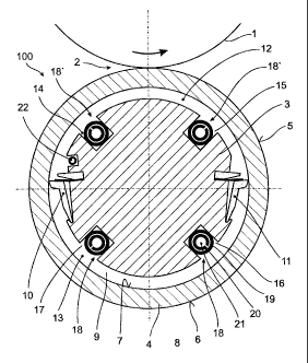
Figure 1 shows the ro~,l in a cross section;
CA 02521521 2005-10-05
WO 200~/09~II0 PCT/EP2004/004320
_ ~ _
Figure 2 shows the same roll ~.n a partly sectioned
longitudinal view and
Figure 3 shows the hydraulic and pneumatic connections
of this roll.
The ro~.l, designated as a whole by 100, is designed as
a so-called floating roll. Wzth an opposing roll 1, ~.t
forms a roll n~.p 2 for the pressure treatment of a
continuous~.~r advancing material band (not represented
in the drawing) . The oppos~.x~g roll 1 may be designed
as a conventional roll,, as a deflection-cantrolled
roll, as a ~laating tall or in any other way desired.
The roll 100 according to the invention comprises a
carrier 3, which is mounted in a rotationally fixed
manner on a machine frame (not represented in the
drawing). Mounted rotatably around the carrier 3 is a
roll shell 4, the outer lateral surface 5 of which
farms the work~.ng circumference 6 of the call 100.
Between the firmer lateral surface 7 of the roll shell 4
and the outer lateral surface 8 of the carrier 3 there
is an annular gap 9, which is subdi~rided by two
mutua~.~.y opposite longitudinal sealing arrangements 10,
~.1 into a pressure chamber 12, facing toward the
oppaszng roller l, and a leakage chamber 13, facing
away from the opposing roller 1.
During the operation of the roll 100, the pressure
chamber 12 contains supporting liquid under a hydraulic
pressure, the pressuxe of which determines the linear
force prevailix~,g in the roll nip 2.
'the leakage chamber 13 serves for receiving and
discharging supporting liquid, which gets i,z~to the
7.eakage chamber past the longitudinal sealing
arrangements 10 , 1 ~, .
CA 02521521 2005-10-05
WO 2001/0971X0 PCT/EP2004/004320
Machined into the carrier 3, distributed over its
circumference, are longitudinal grooves 14. 15, 16, 17,
which serve for respectively accommodating an elastic
element 18, 18', which unrestrictedly communicates with
the supporting liquid and the construction and
operating principle of which are to be further
described below.
The elastic elements 18, 18' are formed as hoses. They
respectively comprise an outer sheath 19 of an elastic
material and supporting means 20, which are arranged in
the internal volume of the outer sheath 19 and prevent
the outer sheath 19 from collapsing even under
1,5 relatively high pressures of the hydraulic supporting
me~xxs .
zn the internal volume 21 of an elastic element 18, 18'
there prevails a pneumatic pressure, the level of which
is regulated in a way described further below on the
basis of Figure 3 in dependence on the level of the
hydraulic pressure exerted on the supporting liquid.
To determine the hydraul~.c pressure Currently
prevailing in the pressure chamber 1.2, a measuring line
22 is provided, connecting the pressure chamber 12 to a
pressure/electrical converter 23 positioned outside the
roll 100 (see ~'igux-e 3) .
The hydraulic and pneumatic connections of the roll 1p0
according t~o the invention are now t~o be described on
the basis of Figure 3,
The elastic elements ~.8 communicating with the leakage
chamber 13 and represented at the bottom of .Figure 1
are connected to a central compressed air source 25 via
a pxzeumatic line 24 and a pressure reducer 25. It goes
without saying that, instead of a single pneumatic line
~4, which is then conriected to the elastic elements
CA 02521521 2005-10-05
Y~10 2004/0971.10 pCT/EP2004/004320
_ g _
located in the leakage chamber 13 via a distributor
(not represented in the drawing), separate pneumatic
lines for one of the elastic elements in each case may
also be provided.
The pressure reducer 25 regulates the pressure to a
value which is less than 1/10 bar higher than the
hydraulic pressure exerted on the hydraulic supporting
medium in the leakage chamber 13, which has an outflow
(not represented in the drawing). The pneumatic
pressure in the pneumatic line 24 is typically about
0.3 bar; the hydraulic pressure in the leakage chamber
13 is typically 0.1 bar.
The elastic elements 18' communicating with the
pressure chamber 12 are connected via a collective line
27 or - alternatively - via individual lines to a
pressure/electrical converter 28, which converts the
pneumatic pressure prevailing zn the internal volume 21
of the elastic elements into an electrical signal. The
latter is fed via an electrical line 29 to an input 30
of a control una.t designated as a whole by 31.
Furthermore, the electrical signal generated by the
pressure/electrical converter 23, which is a measure of
the level of the hydraulic pressure of the supporting
liquid, is fed to the input 30 via az~ electrical line
32.
The control unit 31 compares the two input signals and
produces at its output 33 .an output signal which is
dependent on the difference between, the input, signals
and is fed via an electrical line 34 to the actuating
element 35 0~ a pneumatic pressure regulator 36.
In depender~Ce on the electrical signal, the pressure
regulator 36 regulates the pneumatic pressure exerted
by the external compressed air source 26, which is
typically $ bar, to a value between 0 ax7.d 5 bar, which
CA 02521521 2005-10-05
yrTO 2004/097~.~.0 PCT/Ep2Q04/004320
-9-
is e~certed on a pneumatic line 37 connected to it.
Since in the pressure chamber 12 there may also be
pressures of over 5 bar, sometimes up to 10 bar, the
pneumatic line 37 is connected to the input of a
pressure doubter 38. lts output, at which double the
pressure that pxevails in the pneumatic line 37 is
present, is connected to a pneumatic line 39, which fox
its part opens out into the collective line 27 at the
point 40.
The control unit 31 is connected via a data line 41 to
a monitoring unit 42, which analyzes an,d indicates the
respective operating state of the control unit 31 and
can be remotely actuated by means of an operator
control unit 44 connected vza a modem 43.
CA 02521521 2005-10-05
WO 2004/0971,0 pCTlEP2004/Ofl4320
- 1Q -
List of reference numerals
1 Opposing roller
2 Roll. xiip
3 Carrier
4 Roll shell
Lateral surface
6 Working circumference
7 Lateral surface
$ Lateral surface
9 Annular gap
1p Longitudinal sealing axx~angement
11 Longitudinal sealing arrangement
12 Pressure chamber
13 Leakage chamber
14 Longitudinal grQQVe
Longitudinal groove
I6 Longitudinal groove
1,7 Longitudinal groove
18 Elastic element
19 Outer sheath
Supporting means
21 Internal volume
22 Measuring line
23 Pressure/electrical converter
24 Pneumatic line
Pressure reducer
2~ Compressed air source
27 Collective line
28 Pressure/electrical converter
29 Electrical line
input
31 Control unit
32 Electrical line ,
33 Output
34 Electrical line
Actuating elexner~t
3~ Pressure regulator
CA 02521521 2005-10-05
WQ 2004/097110 pGT/EP200~L/004~20
_ 11 _
37 Pneumatic line
38 Pressure doubler
39 Pneumatic line
40 Point
41 Data line
~2 Monitoring unit
43 Modem
44 Operator Control unit
100 Roll