Note: Descriptions are shown in the official language in which they were submitted.
CA 02523485 2010-12-08
SUPPORT DEVICE IN A SYRINGE PUMP FOR SLIDABLY
BEARING THE FREE END OF THE LEAD SCREW IN A TUBE
BACKGROUND OF THE INVENTION
The invention is related generally to lead screw drive mechanisms for
medical infusion pumps, and more particularly, to a bearing system for
mounting a
lead screw in a syringe pump.
The infusion of fluids such as parenteral fluids into the human body is
accomplished in many cases by means of a syringe pump having a lead screw and
a
screw drive device comprising a mechanism that translates the rotational
motion of
the lead screw into linear motion. The screw drive device is mounted to a
syringe
plunger driver head that typically grasps the plunger flange of a syringe and
that
applies the linear motion of the screw drive device to the syringe plunger to
empty
the syringe at a controlled rate.
Because syringes are of different lengths and are filled with different
amounts of infusion fluids, the extension of the syringe plunger from the
syringe
barrel can differ from syringe to syringe. Many screw drive devices therefore
include a disengagement mechanism that the operator uses to disengage the lead
screw drive device from the lead screw threads. A disengagement mechanism
control is typically located at the plunger driver head and can take the form
of a
lever or levers. Once disengaged, the operator may move the plunger driver
head,
and therefore the screw drive device to the position of the newly-mounted
syringe
plunger flange. The plunger driver head may then engage the syringe plunger
flange and once engaged, the disengagement control may be released at which
time
the plunger driver head will grasp the plunger flange and the lead screw drive
device will engage the threads of the lead screw at the new position. It is
desirable
1
CA 02523485 2005-10-25
WO 2004/096323 PCT/US2004/013173
that this disengagement mechanism and this plunger driver head be easy to use
to
facilitate operator usage of the pump.
Such a lead screw drive device with its integrated disengagement control and
connected plunger driver head, although necessary, can impart substantial
forces on
almost any part of a lead screw. The screw drive device may be located at any
position along the lead screw depending on the length of the syringe mounted
for
use and depending on the level of medical fluid remaining in the syringe.
Additionally, certain medical fluids are more difficult to pump due to their
viscosity
or for other reasons, further placing an increased load on the lead screw. For
these
reasons, it is desirable to provide substantial mounting stability to the lead
screw so
that efficiency is maintained in the development of rotational movement, in
the
translation of that rotational movement to linear movement, and in the
application
of that linear movement to the syringe plunger head.
It is also the goal of syringe pump manufacturers to produce pumps having
increased flow uniformity. That is, manufacturers strive to produce pumps that
will
pump exactly the selected flow rate throughout the infusion and not vary from
that
selected flow rate, until the syringe is exhausted or the rate is changed by
the
operator. However, mechanical tolerances of the syringe pump parts,
interactions
with the syringe, or other reasons can cause the flow rate of a syringe pump
to vary
from the selected rate. A variance from the prescribed and selected flow rate
can be
undesirable, especially if significant, in that the patient may not receive
the desired
level of the infusion fluid when needed. Manufacturers continue to refine
their
pump designs to reduce these variances in flow rate as much as possible.
In one lead screw arrangement, one end of the lead screw, i.e., a first end,
is
mounted through a transfer plate and has a pulley mounted to its end. The
transfer
plate forms a part of the inner frame of the syringe pump and consequently
provides
a stable and rigid mounting point for the lead screw. The lead screw pulley is
directly engaged to the drive pulley of a motor through a drive belt. A
bearing may
surround the lead screw at the portion located through the transfer plate to
lessen
the effects of friction. In another arrangement, both the first end of the
lead screw
and the drive shaft of the motor may have gears and may be interconnected
through
2
CA 02523485 2005-10-25
WO 2004/096323 PCT/US2004/013173
an intermediate gear or gears, although this arrangement can result in less
efficiency. In one design, the second end of the lead screw may also be
mounted to
a rigid plate with a bearing thus providing firm mounting to both ends of the
lead
screw. However, mounting the second end of the lead screw to a rigid mounting
plate is not always an available option, especially when an extension tube
must be
used between the screw drive device and the plunger driver head.
The disengagement mechanism is typically formed as part of the drive
device and permits selective engagement and disengagement of the drive device
with the lead screw so that the drive device may be selectively positioned on
the
lead screw to accommodate different lengths of the syringes. A typical
disengagement mechanism includes half-nuts that are spring loaded into contact
with the threads of the lead screw. Through a series of levers and cams, the
half-
nuts may be moved outwards from engagement with the lead screw threads soy
that
the drive device may be slid along the lead screw to the desired position. The
length of the lead screw and the disengagement mechanism are designed to
easily
move the drive device along a substantial portion of the lead screw so that
the
smallest syringes and the largest syringes for which the pump is designed can
be
used with the pump.
In one particular design, the second end of the lead screw is located within a
hollow connection tube that connects the screw drive device with the plunger
driver
head. The second end of the lead screw is not rigidly mounted but instead
"floats"
within the connection tube. The length of the lead screw is selected to exceed
the
travel of the syringe plunger within the syringe barrel so that syringes of
various
sizes may be accommodated. When the syringe barrel is full, the syringe
plunger
will be at the proximal end of the barrel with the plunger stem extended
almost its
entire length outside the syringe barrel. This configuration results in the
overall
syringe being almost twice the length of its barrel. Because some syringes are
relatively long, the lead screw may be located at one end of the pump housing,
for
example the distal end, with the connection tube extending from the lead screw
to a
point near the other end of the housing, for example the proximal end, to
engage the
syringe plunger stem flange. However, the second end of the lead screw will
3
CA 02523485 2005-10-25
WO 2004/096323 PCT/US2004/013173
always be located within the connection tube regardless of where the syringe
plunger driver head is located.
In the approach described above where the second end of the lead screw is
located within the hollow connection tube and is allowed to "float" in the
tube, rigid
mounting of that second end is not possible. Because there is a size
difference
between the outer diameter of the lead screw second end and the inner diameter
of
the hollow interior of the connection tube, the angle of the lead screw within
the
connection tube can change. Even a slight change in the angle between the two
has
been found to lessen the flow uniformity of the pump. The second lead screw
end
tends to move within the connection tube depending on the forces exerted on
the
lead screw thus adding inefficiency to the translation of the rotational
motion of the
lead screw to the linear motion of the screw drive device. The lead screw
threads
can change their angle of engagement with the screw drive device threads
resulting
in greater or lesser friction between the two and consequently resulting in
lowered
flow uniformity or flow accuracy of the pump.
A further undesirable effect of the floating second end of the lead screw is
that it interacts with the interior of the connection tube scoring or gouging
out the
tube thereby imparting increased wear, and causing a larger difference in size
between the lead screw and the connection tube thereby allowing for even more
movement of the second end of the lead screw in the future.
In an effort to reduce the undesirable effects caused by movement of the
floating lead screw, the floating second end of the lead screw has been
hollowed to
reduce its weight. This has been found to lessen the damage it does to the
connection tube and can lower the amount of movement of the second end
resulting
in greater flow uniformity. However, the manufacturing process of hollowing a
lead screw increases the cost of the screw as well as increases the rate of
lead screw
waste due to errors made during the hollowing process. This waste also
increases
manufacturing costs.
Hence, those skilled in the art have recognized a need for a stabilizing
mechanism to be used with the second end of the lead screw so that the end is
held
in axial alignment with the connection tube and the drive device during
operation.
4
CA 02523485 2010-12-08
Further, those skilled in the art have recognized a need for reducing the
costs of
manufacturing a lead screw. The invention satisfies these needs and others.
SUMMARY OF THE INVENTION
The present invention is directed to a system and method for mounting the
second end of a lead screw within an connection tube such that the lead screw
is
stabilized and aligned with the connection tube is maintained during the
entire range
of movement of the connection tube over the lead screw. The present invention
also
provides for changing the second end of a lead screw such that those lead
screws
previously found to be defective due to poor workmanship are now usable.
Further,
the invention provides for a lead screw that may be solid in configuration
thus
foregoing a manufacturing step of hollowing the screw thus reducing the cost
of the
lead screw.
In one aspect, the invention is directed to a syringe pump having a lead screw
with a drive device in threaded engagement with the lead screw, the drive
device
moving along the lead screw in response to rotation of the lead screw, and a
drive
head adapted to drive a syringe plunger into the barrel of a syringe to expel
fluid
contents of the syringe, the syringe pump comprising: a lead screw having a
first end
and a second end with the first end mounted to a frame, the second end of the
lead
screw comprises a bearing mount having outwardly diverging bearing surfaces; a
connection tube located over the lead screw and connected between the drive
device
and the drive head to communicate movement of the drive device along the lead
screw to the drive head, the connection tube having a hollow portion with an
inner
surface; wherein the second end of the lead screw is located within the hollow
portion
of the connection tube but is otherwise unmounted; and a bearing located at
the
bearing mount in contact with the inner surface of the hollow portion of the
connection tube thereby creating a guided cantilever mount of the second end
of the
lead screw within the connection tube.
5
CA 02523485 2010-12-08
In more detailed aspects, the bearing engaging one or the other of the
diverging bearing surfaces in response to movement of the connection tube over
the
bearing in a particular direction. In further aspects, the outwardly diverging
bearing
surfaces of the bearing mount diverge in axial directions from a bearing
surface center
location, the bearing engaging one or the other of the diverging mounting
surfaces
depending upon the direction of movement of the connection tube over the
bearing.
Further, the bearing mount has a generally hourglass shape.
In yet other aspects, the bearing has inner tapered surfaces for engaging the
diverging bearing surfaces of the bearing mount and the bearing is biased
outwardly
into continuous contact with the inner surface of the connection tube.
Further, the
bearing has an inner surface that is shaped in an approximate complementary
shape to
the diverging bearing surfaces, whereby the bearing locates the second end of
the lead
screw in the approximate center of the connection tube.
In yet other detailed aspects, the bearing and bearing surfaces of the bearing
mount are made of materials selected such that the bearing easily slides along
the
bearing surfaces, whereby the bearing moves up one or the other bearing
surfaces to
maintain contact between the inner surface of the connection tube and the
respective
bearing surface to more accurately center the second end of the lead screw in
the
connection tube.
The present invention also provides a syringe pump having a lead screw with a
drive device in threaded engagement with the lead screw, the drive device
moving
along the lead screw in response to rotation of the lead screw, and a drive
head
adapted to drive a syringe plunger into the barrel of a syringe to expel fluid
contents
of the syringe, the syringe pump comprising: a lead screw having a first end
and a
second end with the first end mounted to a frame; a connection tube located
over the
lead screw and connected between the drive device and the drive head to
communicate movement of the drive device along the lead screw to the drive
head,
the connection tube having a hollow portion with an inner surface; a first end
and a
second end with the first end mounted to a frame; wherein the second end of
the lead
6
CA 02523485 2010-12-08
screw is located within the hollow portion of the connection tube but is
otherwise
unmounted; and a bearing located at the second end of the lead screw in
contact with
the inner surface of the hollow portion of the connection tube thereby
creating a
guided cantilever mount of the second end of the lead screw within the
connection
tube ; wherein the bearing has a larger outer diameter than the inner diameter
of the
hollow portion of the connection tube within which it is mounted, the bearing
having
a discontinuity that permits the bearing to compress to thereby be mounted
within the
connection tube.
The present invention also provides a lead screw mounting system for use in a
syringe pump having a drive head adapted to drive a syringe plunger into the
barrel of
a syringe to expel fluid from the barrel, the lead screw mounting system
comprising: a
lead screw mounted at a first end to a frame; a nut device engaged with the
lead screw
that moves along the lead screw in response to rotation of the lead screw; a
hollow
connection tube located over the lead screw and connected between the nut
device
and the drive head such that movement of the nut device causes movement of the
connection tube over the lead screw and causes movement of the drive head, the
connection tube having an inner surface; wherein a second end of the lead
screw is
continuously located within the hollow of the connection tube; wherein the
second
end of the lead screw comprises a bearing mount; and a bearing located at the
bearing
mount, the bearing having at least one tapered inner surface engaging the
bearing
mount and an outer surface engaging the inner surface of the connection tube
so as to
centrally locate the second end of the lead screw in the connection tube
during
movement of the connection tube along the lead screw.
Other aspects and advantages of the invention will become apparent from the
following detailed description and the accompanying drawings, illustrating by
way of
example the features of the invention.
6a
CA 02523485 2005-10-25
WO 2004/096323 PCT/US2004/013173
BRIEF DESCRIPTION OF THE DRAWINGS
FIGURE 1 is a perspective view of a syringe pump showing a syringe
mounted on the pump for use in infusing its contents to a patient through a
medical
fluid administration set, a drive head in contact with the syringe plunger
flange to
drive the syringe plunger into the syringe barrel to expel the contents of the
syringe
into the fluid administration set that is connected to the vascular system of
a patient;
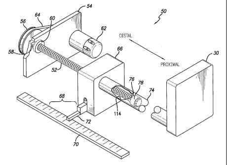
FIG. 2 is a simplified perspective view of the drive device of the syringe
pump of FIG. 1 in which a lead screw is mounted at a first end through a
transfer
plate and has a pulley for drive connection with a motor, the lead screw
having a
floating second end located within an connection tube that connects a drive
device
engaged with the threads of the lead screw with the drive head shown in FIG.
1;
FIG. 3 presents a side view of an embodiment of a lead screw in accordance
with aspects of the invention and as used in FIGS. 1 and 2 showing the first
end
mounted through a cross-sectioned transfer plate via a bearing with a drive
pin, with
the cross-sectioned drive pulley shown mounted to the first end of the lead
screw
via a mounting nut, and the second end of the lead screw having an "hour
glass"
shaped bearing mount, or bearing race, for mounting a bearing;
FIG. 4 is a side view of a bearing in accordance with aspects of the invention
usable with the bearing mount located at the second end of the lead screw of
FIG. 3,
to stabilize the second end of the lead screw within the connection tube of
FIG. 2,
showing the split of the bearing, a plurality of slots in the external surface
of the
bearing, and the inner bearing tapers for engagement with the bearing mount;
FIG. 5 is a perspective view of a cutaway portion of the bearing of FIG. 4
along lines 5 - 5 showing the inner profile that mates with the hourglass
shape of
the bearing mount (race) located at the second end of the lead screw, and the
external bearing surface that mates with the inner surface of the connection
tube;
FIG. 6 is an assembled view of the bearing at the second end of the lead
screw of FIG. 3 in accordance with aspects of the invention, with the bearing
of
FIGS. 4 and 5 in place on the bearing mount, showing the bearing in cross
section;
7
CA 02523485 2005-10-25
WO 2004/096323 PCT/US2004/013173
FIG. 7 shows the bearing in contact with the inner surface of the connection
tube, the bearing also in contact with the proximal diverging surface of the
bearing
mount due to movement of the connection tube in the proximal direction; and
FIG. 8 again shows the bearing in contact with the inner surface of the
connection tube, the bearing in this case being in contact with the distal
diverging
surface of the bearing mount due to movement of the connection tube in the
distal
direction.
DETAILED DESCRIPTION OF THE PREFERRED EMBODIMENTS
Referring now to the drawings with more particularity, wherein like
reference numerals designate like or corresponding elements among the several
views, there is shown in FIG. 1 a view of a syringe pump 10 having a plunger
driver system in accordance with the principles of the invention. A syringe 12
is
shown mounted in the pump with certain mounting and sensing details removed
for
clarity of illustration. The syringe pump includes a syringe cradle 14 in
which the
syringe barrel 16 will rest. The syringe barrel flange 18 will be located in a
barrel
flange groove 20 in the pump 10 to immobilize the syringe barrel from
longitudinal
movement during movement of the syringe plunger 22 within the barrel.
Details of the barrel flange groove are not shown in FIG. 1 nor are they
described here since such a feature is well known to those skilled in the art.
Additionally, the function of the groove in holding a syringe barrel
longitudinally
immobile may be provided by different structure than that shown. Further a
barrel
clamp typically is also used to retain the syringe barrel at its position in
the syringe
pump, but is not shown here in order to preserve the clarity of other
features.
The syringe plunger flange 24, having an inner side 26, is interconnected
with the syringe plunger 22 by a syringe plunger stem 28. When mounted in the
syringe pump 10 properly, the plunger flange 24 is held at a plunger drive
head 30
with a pair of pivotally mounted plunger retaining arms 32, one of which is
shown
in the closed position in FIG. 1. The second pivotally mounted arm has been
removed for clarity purposes. A disengagement lever 34 is used to disengage
the
8
CA 02523485 2010-12-08
plunger drive head 30 from the threads of a lead screw (not shown) as well as
control the positions of the retaining arms 32 to allow removal and insertion
of a
syringe plunger flange 24. Disengaging the plunger drive head 30 from the
threads
of the lead screw permits the operator to move the plunger drive head 30 along
the
lead screw to the correct position to capture the plunger flange of a syringe
12. As
is well known and as is described in the BACKGROUND section, syringes 12
having different quantities of fluid in them may be provided for use with a
syringe
pump 10 and the plunger 22 may be located at different positions in relation
to the
barrel 16. Additionally, syringes of different sizes may be usable in the
syringe
pump 10, which also results in the plunger flange 24 being at different
locations,
depending on the size of the syringe and the level to which it is filled. The
ability
to manually move the drive head 30 permits the accommodation of syringes of
different sizes with different beginning plunger positions.
From the foregoing, it will be appreciated that the plunger driver system as
shown and described provides a versatile system to accept various sizes of
syringes
and results in easier pump operation as well as resists siphoning. For further
details
on a drive head with a disengagement lever and flange-grasping arms, refer to
U.S.
Patent No. 6,428,509 to Fielder, issued on August 6, 2002..
Returning to FIG. 1, the syringe 12 is connected to a patient 36 through a
fluid administration set 38 comprising a length of tubing 40. The tubing 40 is
mounted to a sharpened cannula 42 that has been introduced to a blood vessel
of the
patient 36. As the drive head 30 moves in the distal direction, fluid residing
in the
syringe barrel will be expelled into the tubing 40 of the fluid administration
set 38
and flow into the patient's vein through the cannula 42. It should be noted
that the
administration set 38 may have additional features, such as a pressure sensor
disk,
flow controllers, ports, or other devices mounted to it or formed as part of
it. Such
devices have not been shown in this figure so as to maintain clarity of
illustration of
the basic administration set.
FIG. 2 presents further details of a syringe pump drive assembly 50 showing
a threaded lead screw 52 mounted to a transfer plate 54. The transfer plate
forms
9
CA 02523485 2010-12-08
part of the internal frame of the syringe pump, its anchored nature providing
a rigid
mounting point for the first end of the lead screw. A corner of the transfer
plate 54
has been cut away so that a drive pulley 56 mounted to a first end 58 of the
lead
screw can be more clearly seen. The first end 58 is mounted within a first
bearing
60 for providing a lower friction mounting arrangement with the transfer plate
54.
In this case, the first bearing has been welded to the transfer plate to
achieve a
permanent mounting. A drive motor 62 is also mounted to the transfer plate 54
and
includes a motor pulley (not shown) on the other side of the transfer plate. A
drive
belt 64 interconnects the motor pulley with the drive pulley 56 and transfers
rotary
movement developed by the motor to the drive pulley 56 and thereby, to the
lead
screw 52. Different arrangements of coupling the rotary motion of the motor to
the
lead screw may be used, including a direct drive arrangement or a series of
gears.
Efficiencies may vary depending on the particular drive arrangement chosen.
A screw drive device 66 is mounted to the lead screw 52 and, although not
shown, is prevented from rotating due to its mounting arrangement in the
syringe
pump. Such mounting arrangements are well known to those skilled in the art
and
hence, no further details are provided here. It therefore will translate the
rotation of
the lead screw to linear motion. Because the lead screw is firmly anchored in
the
syringe pump and can only rotate, the drive device will move along the lead
screw.
An optical position determination system 68 is shown comprising a set or
markers
70 with an optical reading device 72. The optical position determination
system
may also be capable of determining the speed of movement of the drive device
66
based on the time between sensing various markers. Such a position-
determination
and speed-of-movement system is known to those skilled in the art and no
further
details are provided here. U.S. Patent No. 5,236,416 to McDaniel, issued on
August 17, 1993 describes such a system.
Other designs and mechanisms may be used to accomplish the same result.
The screw drive device 66 is connected to the plunger drive head 30 that was
shown in FIG. 1 with a hollow connection tube 74. The connection tube is
firmly
mounted to the screw drive device 66 and to the drive head 30. Thus, linear
movement of the screw drive device along the lead screw causes the drive head
to
CA 02523485 2010-12-08
move commensurately. Such a system is known to those skilled in the art and no
further details are provided herein. U.K. Patent No. GB 2 224 444 to Welmed
Limited, inventor B. Lim, published May 9, 1990, describes and shows such a
drive
arrangement.
It will be noted by reference to FIG. 2 that the lead screw 52 resides
partially
within the connection tube 74 and has a second end 76 located fully within the
connection tube. In accordance with the previous description, the drive device
66
moves along the lead screw as the lead screw rotates. Further, the drive
device can
be manually located anywhere along the lead screw so that the drive head 30
may
engage a mounted syringe plunger flange (seen in FIG. 1). For example, when a
large syringe is mounted to the syringe pump and that syringe is full, the
drive head
30 may need to be moved much farther to the right in the figure (proximal
direction), in which case, less of the lead screw will reside within the
connection
tube. As the lead screw is rotated by the motor 62 to move the drive head 30
to the
left direction (distal) in the figure to empty the syringe, more of the lead
screw will
be located within the connection tube. In all cases, the second end 76 of the
lead
screw will always be located within the connection tube.
To overcome some of the problems facing prior syringe pump drive devices
as previously reviewed, the second end 76 of the lead screw 52 in the
embodiments
shown includes a connection tube bearing 78 in accordance with aspects of the
invention. The bearing is configured to make contact with the inner surface of
the
connection tube to keep the second end 76 of the lead screw better centered
within
the connection tube 74. Other than the bearing, the second end of the lead
screw is
unmounted. The lead screw is thus generally in a cantilever arrangement;
however,
the addition of the bearing that contacts both the lead screw second end and
the
inner surface of the connection tube results in a "guided cantilever mounting"
of the
second end of the lead screw. This "guided" mounting has been found to result
in
the lead screw constantly being concentric with the connection tube which
greatly
improves flow uniformity of the syringe pump.
Referring to FIG. 3, a side view of the lead screw 52 is shown. The transfer
plate 54, lead screw pulley 56, and the first bearing 60 are shown. As
mentioned
11
CA 02523485 2005-10-25
WO 2004/096323 PCT/US2004/013173
above, in a preferred embodiment the first bearing 60 is welded to the
transfer plate;
however, it may be press fit or held in place through other means. The pulley
56
may be mounted to the lead screw in various well known ways. In this case, the
pulley has a drive pin 80 that assures rotation of the pulley with the
rotation of the
lead screw 52, and a retaining nut 82 that affixes the pulley to the first end
58 of the
lead screw. Other mounting techniques for both the bearing and the pulley are
possible.
At the second end, or proximal end 76, of the lead screw 52, a bearing mount
84 or bearing race is formed. Formed at a location proximal to the threads 85
and
between the threads and the bearing mount is a thread undercut 86. The bearing
mount has a land 88 at each end with outer chamfers 90. The outer chamfers
facilitate sliding the bearing mount into the connection tube. The bearing
mount
also comprises two outwardly diverging bearing surfaces 92 separated by a
bearing
mount undercut 94. The bearing mount 84 has the general appearance of the
shape
of an hourglass. The bearing mount undercut 94 is a production feature
providing a
convenient place in which the bearing may be compressed during the process of
sliding the second end 76 of the lead screw into the connection tube 74. The
crest
of the bearing, as is shown and described below, will be located at least
initially in
the undercut 94 and because of the depth of the undercut, bearings of
differing sizes
may function well in the bearing mount 84. This permits the bearings to be
made
with looser tolerances which reduces manufacturing costs.
A suitable lead screw bearing 100 in accordance with aspects of the
invention is shown in FIGS. 4 and 5. The bearing comprises an outer bearing
surface 102, an inner bearing crest 104, two tapered surfaces 106, and
chamfers 108
on either side of the outer bearing surface. The bearing is split 110 as shown
in
FIG. 4 to allow the bearing to be more easily mounted over the bearing mount
84.
Three slots 112 are also formed in the outer bearing surface to control the
points of
bending of the bearing. Because the slots are spaced at ninety degrees from
each
other, including the split 110, the bearing more uniformly applies outward
pressure
to the connection tube, which provides better centering action of the lead
screw
within the connection tube. The three notches 112 and the split 110 have the
effect
12
CA 02523485 2005-10-25
WO 2004/096323 PCT/US2004/013173
of producing four segments with a more controlled spring effect as well as
making
the bearing easier to compress when inserting it into the connection tube 74.
Although three notches are shown in this embodiment, more or fewer notches may
be used as desired.
In FIG. 6, the bearing 100 is shown mounted to the bearing mount 84 of the
lead screw 52. The crest 104 of the bearing is located within the bearing
mount
undercut 94 of the bearing mount which provides a good starting position for
the
bearing. It will be noted from the figure that when centered on the bearing
mount,
the bearing inner diameter is larger than the outer diameter of the
corresponding
points of the bearing mount 84 and the outer diameter of the bearing is larger
than
the outer diameter of the threads of the lead screw 52. This is so that the
outer
surface of the bearing will always make contact with the inner surface 114 of
the
connection tube 74 (FIG. 2). The connection tube is typically formed by
injection
molding and because of that process, the inner channel 114 through the
connection
tube is tapered from one end to the other. Consequently the lead screw bearing
78
must be able to accommodate the tapering inner diameter of the connection
tube.
Hence, the outer diameter of the lead screw bearing is set so that it will
make
contact with the largest inner diameter of the connection tube. The chamfers
108 of
the bearing 78 shown in FIG. 4 assist in mounting the second end 76 of the
lead
screw within the connection tube 74. Whether the second end of the lead screw
is
pushed forward into the connection tube or drawn rearward into the connection
tube, the outer chamfers provide an angle of contact between the bearing and
the
ends of the connection tube that tend to compress the bearing so that
insertion into
the connection tube is facilitated. Additionally, the chamfers remove any
sharp
edges of the bearing that may have otherwise provided greater friction with
the
inner surface of the connection tube once the bearing is mounted within the
connection tube.
Additionally, the bearing 78 tapered surfaces 106 are complementary to the
diverging surfaces 92 of the bearing mount 84. Because the bearing 100 is
formed
of a low friction substance, it will easily slide along the diverging surfaces
92 of the
bearing mount as needed to maintain the lead screw second end 78 centered
within
13
CA 02523485 2005-10-25
WO 2004/096323 PCT/US2004/013173
the connection tube 74. The diverging surfaces 92 of the bearing mount give
the
mount a general hourglass appearance. It can also be noted that the bearing
mount
84 is symmetric about the bearing mount under cut 94 and this shape provides a
distinct advantage, as is demonstrated in FIGS. 7 and 8.
Referring now to FIG. 7, the bearing 100 and bearing mount 84 located at
the second end 76 of the lead screw 52 are shown mounted within the connection
tube 74, which is partially shown. The bearing is in contact with the inner
surface
114 of the connection tube. Because the connection tube is being drawn in the
proximal direction, possibly because the drive head 30 is being attached to a
new
syringe (FIG. 1), the friction between the bearing outer surface 102 and the
inner
surface 114 of the connection tube draws the bearing up the proximal diverging
surface 116 of the bearing mount in a "wedging" action. Because the tapered
bearing surfaces 106 have the same angle as the diverging bearing surfaces 92
of
the bearing mount 84, an inclined plane type of arrangement results. This
wedging
action has the effect of providing even more stabilizing force against the
lead screw
to keep it centered within the connection tube.
FIG. 8 presents another condition in which the connection tube 74 is being
moved over the second end 76 of the lead screw 52, this time in the distal
direction.
This is probably due to the syringe pump 10 being operated to expel the
contents of
the syringe 12 into the administration set 38 (FIG. 1). Consequently, the
drive head
and connection tube 74 are moving toward the syringe barrel 16, in the distal
direction. Because the connection tube is being drawn in the distal direction,
the
friction between the bearing outer surface 102 and the inner surface 114 of
the
connection tube draws the bearing up the most distal diverging surface 118 of
the
25 bearing mount in the wedging action described above. As also mentioned,
this
wedging action has the effect of providing even more stabilizing force against
the
lead screw to keep it centered within the connection tube, and in this case
where
medical fluid is being infused into the patient, this centering action has
been found
to result in better flow uniformity from the syringe pump.
30 This wedging action results because the bearing 100 is larger than the
inner
diameter of the connection tube 74 and consequently exerts a continual force
14
CA 02523485 2005-10-25
WO 2004/096323 PCT/US2004/013173
against the interior of the connection tube, and because of the friction
between the
inner surface 114 of the connection tube and the outer surface 102 of the
bearing.
Additionally, the diverging surfaces 92 of the bearing mount 84 and the
complementary tapered surfaces 106 of the bearing 100 facilitate movement of
the
bearing into the wedging action.
The lead screw may be formed of stainless steel with an electroless nickel
plate. The bearing may be formed of DelrinTM material, an acetal resin
available
from E.I. DuPont de Nemours and Company. The connection tube may be formed
of glass-filled nylon. Other materials may be used for these components as
well.
While in the present embodiment, the bearing mount is cut from the same
piece of material as the threaded portion of the lead screw, other approaches
are
possible. For example, in the case where hollowed lead screws exist, the
bearing
mount may be made separately and attached to the proximal end of the lead
screw,
such as by adhesive or welding thereby salvaging lead screws or possibly
providing
a lower cost lead screw.
Although specific embodiments of the invention have been described and
illustrated it is clear that the invention is susceptible to numerous
modifications and
embodiments within the ability of those skilled in the art, and without the
exercise
of the inventive faculty. Thus, it should be understood that various changes
in
form, detail and application of the present invention may be made without
departing
from the spirit and scope of the invention.