Note: Descriptions are shown in the official language in which they were submitted.
CA 02524278 2012-08-14
SUCTION COAGULATOR WITH DISSECTING PROBE
BACKGROUND
The present invention relates generally to electrosurgical
coagulators and, more particularly to an electrosurgical suction coagulator
having a selectively extendible dissecting probe attached to a distal end
thereof.
Technical Field
The coagulation of bleeding blood vessels and tissue using
electrically conductive suction tubes is a technique which has been widely
used
for some time. Typically, a combination electrocautery and suction device is
employed in surgery wherever excessive blood must be removed from the
bleeding site in order to facilitate hemostasis of any bleeding vessels, More
particularly, during any given surgical procedure, several layers of tissue
usually
must be penetrated to reach the operative field, When excising an organ, such
as a gallbladder, the tissue Surrounding the organ must be penetrated and
CA 02524278 2005-10-31
WO 2004/098382
PCT/US2004/013106
dissected before the organ can be removed. The tissues being dissected,
however, often contain blood vessels, nerves, lymph vessels, and the like,
which
should not be severed. The technique of blunt dissection is often used to
prevent
unnecessary damage caused by severing these vessels or nerves.
Blunt dissection, as opposed to sharp dissection, involves the use
of a blunt surface to break through the tissue, thereby preventing the damage
and bleeding caused by lasers and scalpels, the tools of sharp dissection.
Hard
surgical sponges, generally known as peanuts or Kittner sponges, or a
surgeon's
fingers are often used as blunt dissectors. A peanut is a tightly wound ball
of
absorbent material, such as gauze or other woven cotton, which is typically
gripped with forceps and acts to abrade the tissue being dissected so that the
dissection can be performed by either pulling on the tissue or by forcing the
peanut through the tissue.
Laparoscopy, surgery performed through several small incisions
made in the body rather than through a single large opening, is quickly
becoming
the preferred method of performing certain procedures due to the reduced
trauma and risk of infection as compared to normal, open surgical procedures.
As a result, the use of conventional blunt dissectors, such as the peanut,
during
laparoscopic procedures presents many significant drawbacks. For instance,
peanuts, being secured only by forceps, can become loose in the body. Further,
the view of the operative field often becomes obstructed by pieces of tissue,
blood and other bodily fluids produced during blunt dissection, necessitating
the
2
CA 02524278 2005-10-31
WO 2004/098382
PCT/US2004/013106
immediate need for both irrigation and aspiration of the operative field.
Since it is
undesirable to create additional incisions, the dissection must be stopped,
the
dissector must be removed, and an irrigator and/or aspirator must be inserted
to
remove the fluid and debris.
Electrosurgical suction coagulators which both coagulate and
dissect tissue have also been available for some time. Generally, these
devices
include a conductive suction tube having an insulating coating over all but a
most
distal portion of the tube so that the distal portion forms a generally
annular
ablating electrode. The distal end can be used as a blunt dissection device
and/or a blunt coagulator. A suction source is attached to a proximal portion
of
the tube for evacuating excess fluid and debris from the surgical site through
the
distal end of the tube. While known electrosurgical devices are used to effect
hemostasis, such devices have not been optimized and, in particular, the
electrodes do not provide for precision coagulation of tissue. In other words,
the
very nature and configuration of the ring-like electrodes do not allow for
precise
dissection, ablation or coagulation of tissue, i.e., circular, ring electrodes
are
blunt and do not provide precise electrode control.
Moreover, it is known that ring-like electrosurgical suction
coagulators can clog at the distal end with blood or tissue during operation,
interrupting the henriostasis procedure and requiring additional effort by the
operating physician and staff. The suction prevents the electrode from moving
smoothly over a target area. A vacuum port on the handle may be employed
3
CA 02524278 2005-10-31
WO 2004/098382
PCT/US2004/013106
to selectively reduce the amount of suction during activation, however, the
suction effect at the end is not eliminated. As evident in use, the clog
occurs
from eschar buildup on the end of the suction tube where the electrosurgical
heat is being created. Further, it is believed that the heat cannot be
properly
dissipated when the opening is occluded by the tissue targeted for the
electrosurgical effect.
Ventilation ports also tend to hinder 360 degree operation of a
device, in that a physician cannot easily rotate a device while maintaining
his/her
finger over the ventilation port. By and large, these devices are expensive,
cumbersome and difficult to manipulate in the operating field and often
require
cleaning during the surgical procedure thus requiring the surgeon to remove
the
instrument from the operating cavity for cleaning.
Thus there exists a need to develop a coagulating and dissecting
instrument that can dissect tissue in a more precise manner and which is less
prone to clogging during use. Such a device would be a welcome advance in the
art, particularly when such benefits are realized in a rugged, reliable, and
relatively simple design.
SUMMARY
The surgical coagulator according to the present disclosure
includes a handle having an elongated conductive tube-like electrode or
suction
tube electrode extending from a distal end of the handle. The elongated
suction
tube includes a substantially blunt or closed distal end for delivering
coagulating
4
CA 02524278 2005-10-31
WO 2004/098382
PCT/US2004/013106
current to the operating area for blunt or gross dissection. An elongated slot
is
disposed through the suction tube electrode and is dimensioned to slideably
receiving a needle or wire electrode. The
needle electrode is selectively
extendible relative to the closed distal end to facilitate precise dissection.
When
the needle electrode is retracted, the user can use the blunt distal end for
blunt
coagulation and dissection. At least one aspiration port is disposed along a
side
of the suction tube electrode for removing surgical fluids and debris from the
operating area. Preferably, the port or ports are positioned circumferentially
around the suction tube electrode to prevent obstructing the tube when
coagulating tissue.
Preferably, the needle electrode and/or the suction tube electrode
are substantially flexible or malleable to facilitate dissection and
manipulation of
the coagulator in the operating field. The
needle electrode may be
manufactured by plant cutting a small gauge wire which may be made from a
refractory alloy or the like. In one embodiment, the coagulator includes one
aspiration port which extends generally from a proximal end of the suction
tube
electrode to the distal end of the suction tube electrode. In another
embodiment,
the suction tube electrode includes one aspiration port which extends
transversally through the suction tube electrode.
Preferably, the coagulator includes at least one control switch for
activating the suction tube electrode and/or the needle electrode either
independently or concurrently. Alternatively, the coagulator may include a
CA 02524278 2005-10-31
WO 2004/098382
PCT/US2004/013106
series of switches, dials and/or slide switches for controlling one or both of
the
electrodes in terms of waveform, intensity, voltage, current, surgical effect,
etc.
Another embodiment of the present disclosure includes a surgical
coagulator having a handle which includes an elongated suction electrode
extending from a distal end thereof which is selectively energizable by the
user
to accomplish a surgical purpose. The suction tube may also be rotatable
relative to the handle. The suction tube electrode includes both a
substantially
blunt distal end for delivery coagulating energy to tissue and at least one
aspiration port disposed along a side of the suction tube electrode. In yet
another embodiment, the suction tube electrode is selectively extendible from
the distal end of the handle. This embodiment of the coagulator may also
include an elongated slot disposed in the suction tube electrode for slideably
housing a needle electrode. Preferably, the needle electrode is selectively
extendible from the blunt distal end of the suction electrode and selectively
activateable to coagulate tissue as needed for precise dissection.
In still yet another embodiment of the present disclosure, the
coagulator includes a selectively activateable valve for regulating the flow
of
surgical fluids and debris through the aspiration port. Preferably, the valve
includes a generally arcuate sleeve which is rotated within the suction tube
electrode to regulate the flow through the aspiration port.
6
CA 02524278 2005-10-31
WO 2004/098382
PCT/US2004/013106
These and other objects will be more clearly illustrated below by
the description of the drawings and the detailed description of the various
embodiments.
BRIEF DESCRIPTION OF THE DRAWINGS
The accompanying drawings, which are incorporated in and
constitute a part of this specification, illustrate embodiments of the present
disclosure and, together with a general description of the disclosure given
above,
and the detailed description of the embodiments given below, serve to explain
the principles of the present disclosure.
FIG. 1A is a perspective view of one embodiment of a surgical
coagulator in accordance with the present disclosure showing a dissecting
needle electrode in an extended position;
FIG. 1B is a perspective view of the embodiment of Fig. 1 showing
the dissecting needle electrode in a retracted position;
FIG. 2 is a perspective view of an alternate embodiment of a
surgical coagulator in accordance with the present disclosure having a blunt
dissector at a distal end thereof and a side aspiration port;
FIG. 3 is a perspective view of an alternate embodiment of a
surgical coagulator in accordance with the present disclosure having a closed-
7
CA 02524278 2005-10-31
WO 2004/098382
PCT/US2004/013106
end dissector at a distal end of the handle and a selectively extendible
needle
electrode extending from the distal end of the closed-end dissector;
FIG. 4 is a perspective view of an alternate embodiment of a
surgical coagulator in accordance with the present disclosure having a
selectively extendible needle electrode and a selectively rotatable aspiration
port
disposed at a distal end thereof; and
FIG. 5 is a perspective view of an alternate embodiment of a
surgical coagulator in accordance with the present disclosure having a side
aspiration port located at a distal end thereof and a selectively adjustable
control
valve for regulating the amount of suction through the aspiration port.
DETAILED DESCRIPTION
Preferred embodiments of the presently disclosed electrosurgical
instrument will now be described in detail with reference to the drawing
figures
wherein like reference numerals identify similar or identical elements. As
used
herein, the term "distal" refers to that portion of the instrument which is
further
from the user while the term "proximal" refers to that portion of the
instrument
which is closer to the user.
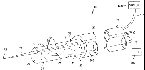
FIG. 1A sets forth a perspective view of an electrosurgical
coagulator constructed in accordance with the present disclosure and generally
referenced by numeral 10. Coagulator 10 includes a handle 20 having proximal
8
CA 02524278 2005-10-31
WO 2004/098382
PCT/US2004/013106
and distal ends 21 and 22, respectively, and an elongated tube-like electrode
or
suction tube electrode 30 which extends from the distal end 22. Suction tube
electrode 30 includes a closed and substantially blunt distal end 36 which is
dimensioned for use during gross dissection or blunt dissection. It is
envisioned
that the distal end 36 may be rounded or include a pattern of protuberances to
facilitate coagulation of tissue at or adjacent the distal end 36 when
activated.
Suction tube electrode 30 is electrically interfaced to a source of
electrosurgical
energy such as an electrosurgical generator (ESU) 500 via cable 505. As
schematically shown in Fig. 1A, the ESU 500 may include one or more electrical
connections 505 to supply electrosurgical energy to the suction tube 30. As
explained in more detail below, the ESU 500 may include one or more switches
to control the amount of electrosurgical energy delivered through the suction
tube electrode 30 and to the tissue. A return pad (not shown) may be utilized
to
complete the electrical circuit through the patient.
Suction tube electrode 30 also includes an elongated slot 33
disposed therethrough which extends generally from the distal end 36 the tube
electrode 30 to a proximal end 32 of the tube electrode 30. Slot 33
is
dimensioned to house a needle or wire electrode 40 which is selectively
extendible from an aperture 37 disposed in the distal end 36 of the suction
tube
electrode 30. Needle electrode 40 is preferably tapered to form a point 42 at
the end thereof to facilitate delicate and precise dissection of tissue. One
or
more wires or electrical interfaces 39 are connected to the needle electrode
40
to communicate electrosurgical energy from the ESU 500. It is envisioned that
9
CA 02524278 2005-10-31
WO 2004/098382
PCT/US2004/013106
the needle electrode 40 may be independently energizable from to the suction
tube electrode 30 or energized concurrently through the same electrical
interface. Alternatively, the needle electrode 40 could be isolated from the
suction tube electrode 30 depending upon a particular purpose, e.g., to create
a
different surgical effect on tissue when activated or to create a bipolar
electrical
arrangement. Several envisioned embodiments are explained in more detail
below.
As mentioned above, the needle electrode 40 is selectively
extendible from the distal end 36 of the suction tube electrode 30. More
particularly, the coagulator 10 may include one or more control rods 45 which
allow a user to selectively advance the needle electrode 40 from the distal
end
36 to facilitate delicate dissection and coagulation of tissue and selectively
retract the needle electrode 40 to grossly dissect and coagulate tissue using
the
blunt distal end 36 of the suction tube electrode 30. In one embodiment, the
needle electrode 40 is attached to a distal end 48 of the control rod 45 by a
control wire 46 which operates to extend and retract the needle electrode 40
within elongated slot 33. It is envisioned that the control rod 45 may be
dimensioned to both mechanically advance and retract the needle electrode 40
and also electrically connect the needle electrode 40 (and the suction tube
30) to
the ESU 500. The needle electrode may be manufactured by plant cutting a
small gauge wire which may be made from a refractory alloy or the like.
CA 02524278 2005-10-31
WO 2004/098382
PCT/US2004/013106
Preferably, the needle electrode 40 and the suction tube electrode
30 are made from flexible and/or malleable materials to give the user
additional
control of the coagulator 10 during use. It is contemplated that the needle
electrode 40 and the suction tube electrode 30 may be made from the same
material or different materials depending upon a particular purpose. For
example, the needle electrode 40 could be made from a more resilient material
to facilitate delicate dissection or a refractory material to prevent melting
of the
electrode during use.
The suction tube electrode 30 also includes at least one aspiration
port 35 disposed through a side 31 thereof. More particularly and as best
shown
in Fig. 1A, the suction tube electrode 30 is preferably connected to a source
of
negative pressure, i.e., vacuum 600, which draws air and fluid into the
aspiration
port 35 and into the vacuum via hose 610 upon activation. Preferably, the
aspiration port 35 is dimensioned to facilitate removal of surgical fluids and
debris from the surgical site. More particularly, the aspiration port 35 may
be
chamfered, beveled or some other advantageous shape to create a smooth fluid
stream therethrough and into the suction tube electrode 30 when activated
enabling the coagulator 10 to operate in a similar fashion to a suction wand.
It is envisioned that providing the aspiration port(s) 35 on the side
of the suction tube electrode 30 will significantly reduce the chances of the
coagulator 10 clogging during use. More particularly, the closed distal end 36
of
the suction tube electrode 30 and the needle electrode 40 both remain free of
11
CA 02524278 2005-10-31
WO 2004/098382
PCT/US2004/013106
debris buildup and clogging due to the negative pressure or suction
redirecting
fluid and debris away from the needle electrode 40 and the distal end 36 of
the
suction tube electrode 30 and into the side aspiration port(s) 35. As can be
appreciated, a series of aspiration ports 35 may be disposed along the length
of
the suction tube electrode 30 depending upon a particular purpose.
As mentioned above and as best shown in Fig. 1B, the needle
electrode 40 is selectively extendible and retractable within elongated slot
33 and
relative to the distal end 36 of the suction tube electrode 30 via control rod
45. It
is envisioned that the coagulator 10 may be configured such that upon
extension
of the needle electrode 40 energy is automatically switched from the suction
tube
electrode 30 to the needle electrode 40. Upon retraction, the energy switches
back to the suction tube electrode 30 for blunt dissection. It is envisioned
that a
mechanical, electromechanical or simply electrical switch may be employed to
accomplish this purpose. A seal or the like (not shown) may be employed to
prevent surgical fluid and/or debris from entering slot 33.
Fig. 2 shows an alternate embodiment of a coagulator 100
according to the present disclosure which includes a handle 120 having an
elongated suction tube electrode 130 extending therefrom. Suction tube
electrode 130 includes a substantially blunt distal end 136 and an aspiration
port
135 disposed through a side 131 thereof. The suction tube electrode 130 is
connected to ESU 500 via electrical connection 505 to allow selective
activation
of the suction tube electrode 130 to coagulate tissue. Preferably, the distal
end
12
CA 02524278 2005-10-31
WO 2004/098382
PCT/US2004/013106
136 of the suction tube electrode 130 is dimensioned to facilitate gross
coagulation and dissection of tissue. As mentioned above, locating the
aspiration port(s) 135 along the side 131 of the suction tube electrode 130
reduces the likelihood of coagulum building up at the distal end 136 due to
the
aspiration port 135 clogging during use.
Fig. 3 shows yet another embodiment of a coagulator 200
according to the present disclosure which includes a control switch 520 which
regulates the electrosurgical energy to the needle electrode 240 and the
suction
tube electrode 230. More particularly, the control switch 520 includes a
plurality
of switches 522 and 524 which regulate, measure, monitor and/or control one or
more of the following electrical or electromechanical parameters: electrical
intensity, voltage, current, pulse rate, waveform, temperature and impedance.
It
is envisioned that the control switch 520 may cooperate with one or more
sensors (not shown) to regulate certain parameters. A rotating or sliding type
switch may be employed to accomplish this purpose. A series of computer
algorithms may also be utilized to regulate, control and/or monitor the
sensors or
the switches to optimize or control various surgical effects. As mentioned
above,
the same control switch 520 may regulate both electrodes 230 and 240 or a
second control switch may control either electrode 230 or 240 independently.
Each electrode 230 and 240 is connected to the control switch 520 by a lead or
electrical connection 505 and 525, respectively.
13
CA 02524278 2005-10-31
WO 2004/098382
PCT/US2004/013106
It is envisioned that the needle electrode 240 may be automatically
energized upon extension and deactivated upon retraction. Similarly, the
control
switch 520 may deactivate the suction tube electrode 230 when the needle
electrode 240 is extended and activated and automatically reactivate the
suction
tube electrode 230 when the needle electrode 240 is deactivated. It is
contemplated that the user may selectively interchange between electrodes 230
and 240 simply by extending and retracting the needle electrode 240 while
continually actuating an activation switch, e.g., footswitch or hand switch
(not
shown). It is also contemplated that the needle electrode 240 and the suction
tube electrode 230 can be pre-set or pre-programmed to deliver different
surgical
effects or different energy intensities depending upon a particular purpose or
to
facilitate dissection.
Fig. 4 shows yet another coagulator 300 according to the present
disclosure wherein the suction tube 330 is slidingly and rotatably received
within
a channel 325 disposed in the distal end 322 of the handle 320. More
particularly, the suction tube 330 is positioned within the channel 325 to
permit a
user to slidingly extend and rotate the suction tube electrode 330 as needed
during surgery. A control rod 347 is mechanically coupled to the proximal end
332 of the suction tube 330 and is manipulatable by the user to extend,
retract
and/or rotate the suction tube 330 to facilitate dissection and aspiration of
the
operating area. More particularly, the user can manipulate the needle
electrode
340 via the control rod 345 (which operates in a similar manner as described
above) and/or via the control rod 347 which would allow the user to rotate the
14
CA 02524278 2005-10-31
WO 2004/098382
PCT/US2004/013106
needle electrode 340 within the operating area. In addition, the aspiration
port(s)
335 can be rotated, extended and retracted into position to aspirate and clean
the operating area during use. Moreover, the suction tube electrode 330 can be
manipulated into position to facilitate gross dissection of tissue.
Fig. 5 shows yet another embodiment of a coagulator 400
according to the present disclosure which includes a control valve disposed
over
the aspiration port 435. More particularly, the coagulator 400 includes an
elongated sleeve 450 which is interleaved within the inner periphery of the
suction tube 430. The sleeve 450 is selectively rotatable from a first, open
position which does not impede the influx of surgical fluids and debris
through
the aspiration port 435 to a series of subsequent positions in which the
sleeve
450 incrementally impedes the flow of fluids through the aspiration port 435
and
regulates the overall suction energy of the aspiration port 435. It is
envisioned
that the sleeve 450 may be configured in a different manner to accomplish the
same purpose, i.e., the sleeve 450 may be selectively extendible over the
aspiration port 435 to regulate suction.
From the foregoing and with reference to the various figure
drawings, those skilled in the art will appreciate that certain modifications
can
also be made to the present disclosure without departing from the scope of the
present disclosure. For example, it is contemplated that the presently
disclosed
coagulator may be manufactured such that -the coagulator is disposable,
reusable or reposable. It is
envisioned that a variety of different or
CA 02524278 2005-10-31
WO 2004/098382
PCT/US2004/013106
interchangeable needle electrodes could be selectively attached to the distal
end
of the control rod depending upon a particular purpose or to meet a particular
surgical need. It is also envisioned that the coagulator may be designed such
that the tip of the needle electrode is removably engageable thus allowing a
surgeon to selectively engage variously-sized and variously-shaped tips for
dissection purposes.
It is contemplated that positioning the aspiration/ventilation ports 35
on the side of the suction tube electrode 30 is effective at eliminating
debris from
the surgical field and limits eschar buildup. As can be appreciated,
positioning
multiple ports 35 around the circumference of the suction tube electrode 30
further reduces the chances of obstructing the suction tube. It is also
envisioned
that by allowing free flow of fluid through the tube will essentially cool the
suction
electrode and dissipate heat thus further reducing overall eschar buildup
around
the suction ports 35.
While several embodiments of the disclosure have been shown in
the drawings, it is not intended that the disclosure be limited thereto, as it
is
intended that the disclosure be as broad in scope as the art will allow and
that
the specification be read likewise. Therefore, the above description should
not
be construed as limiting, but merely as exemplifications of preferred
embodiments. Those skilled in the art will envision other modifications within
the
scope and spirit of the claims appended hereto.
16