Note: Descriptions are shown in the official language in which they were submitted.
CA 02524570 2005-11-O1
WO 2004/098715 PCT/US2004/013763
TITLE OF THE INVENTION
LIGHTWEIGHT VENTILATED FACE SHIELD FRAME
CROSS-REFERENCE TO RELATED APPLICATIONS
s [0001] This application claims priority from U.S. provisional application
serial
number 60/461,791 filed on 05/02/04, incorporated herein by reference in its
entirety.
STATEMENT REGARDING FEDERALLY SPONSORED RESEARCH
1o OR DEVELOPMENT
(0002] Not Applicable
INCORPORATION-BY-REFERENCE OF MATERIAL
SUBMITTED ON A COMPACT DISC
15 [0003] Not Applicable
NOTICE OF MATERIAL SUBJECT TO COPYRIGHT PROTECTION
[0004] A portion of the material in this patent document is subject to
copyright
protection under the copyright laws of the United States and of other
2o countries. The owner of the copyright rights has no objection to the
facsimile
reproduction by anyone of the patent document or the patent disclosure, as it
appears in the United States Patent and Trademark Office publicly available
file or records, but otherwise reserves all copyright rights whatsoever. The
copyright owner does not hereby waive any of its rights to have this patent
2s document maintained in secrecy, including without limitation its rights
pursuant
to 37 C.F.R. ~ 1.14.
BACKGROUND OF THE INVENTION
1. Field of the Invention
30 [0005] The present invention pertains to head-mounted face shield frames
and more particularly to a fight weight, ventilated, frame having an open
tiered
structure that provides rigidity while reducing frame weight.
-1-
CA 02524570 2005-11-O1
WO 2004/098715 PCT/US2004/013763
2. Description of Related Art
[0006] In a number of industries, the use of a face shield provides protection
for the eyes and face of the wearer from debris or biological materials.
Increasingly, face shields are being utilized for preventing infections that
can
occur as a result of bodily fluid splattering that can arise within a number
of
occupations. A number of factors affect the acceptance of a face shield
design, including comfort, ventilation, weight, ability to be securely
retained in
position, cost, and aesthetic considerations. The need for secure positioning
and ventilation, which increases comfort while reducing the possibility of
o fogging, can be critical performance factors, especially in situations in
which
the face shield needs to be worn for extended periods of time.
[0007] ~ The type of face shields being described herein attach to the head of
a
user with support arms that extend rearwardly from a frame upon which is
retained a transparent face shield that affords debris and splatter protection
to
15 the wearer. To provide a secure and comfortable fit, the support arms are
preferably configured to have sufficient horizontal stiffness to support a
transparent shield which is separated sufficiently far from the face, without
causing discomfort to the user.
[0008] A number of examples of practical face shields exist. Examples of face
2o shields which are being increasingly utilized in a number of industries may
be
found in the following United States Patents by Timothy J. Landis, including
Patent numbers: 4,852,186 of August 1, 1989 entitled "Combined Visor and
Protective Shield", Patent number 4,864,653 of September 12, 1989 entitled
"Protective Shield and Visor Supporting Same", Patent Number 4,964,171 of
2s October 23, 1990 entitled "Protective Shield and Visor", Design Patent
375,583 of November 12, 1996 entitled "Disposable Face Shield", Patent
Number 5,692,522 of December 2, 1997 entitled "Face Shield Apparatus",
and Patent Number 6,016,808 of January 25, 2000 entitled "Face Shield
Frame Apparatus". The above face shields provide numerous benefits and
so are included herein by reference. It will be appreciated, however, that the
growing market for face shields is always in search of improved face shield
designs that provide increasing utility, comfort, and style while reducing
-2-
CA 02524570 2005-11-O1
WO 2004/098715 PCT/US2004/013763
material requirements and manufacturing costs.
[0009] Therefore, a need exists for a lightweight face shield frame that can
be
maintained securely in position while providing ample ventilation, and which
can be manufactured at low cost and stored compactly. The present invention
satisfies those needs, as well as others, and overcomes the deficiencies of
previously developed face shield designs.
BRIEF SUMMARY OF THE INVENTION
[0010] The present invention describes a face shield apparatus and method of
forming a lightweight tiered face shield frame with enhanced retention,
o ventilation and comfort while designed to allow manufacturing it in stylish
configurations. The open design of the frame within the present invention
provides necessary rigidity while reducing material weight. The tiered design
of the present invention is stylish and readily manufactured, while utilizing
only
small amounts of material.
15 [0011] The present face shield apparatus comprises a two piece frame with a
retention frame member interconnected through an inclined support structure
with a shield frame member. A transparent shield is attached to and extends
below the shield frame member, while a minishield member is retained above
the shield frame member to control the amount of shading provided over the
2o eyes of the wearer while providing debris protection. The optional
minishield
may be attached to the face shield frame as received by a customer, or may
be user installable, depending on the need. The tiered arrangement of the
face shield frame allows retaining the transparent shield in separation from
both the front and sides of the wearer's face with a view towards increasing
25 ventilation and reducing the opportunity for fogging of the transparent
shield.
[0012] The retention frame of the invention provides sufficient structural
rigidity
for being retained securely on the head, and with flexure that is distributed
about the retention frame to properly accommodate varying head sizes.
Points of contact between the retention frame and the head of the wearer is
so preferably limited to a region at the front interior of the retention frame
and
portions of the support arms which meet the head behind the location of the
ears.
-3-
CA 02524570 2005-11-O1
WO 2004/098715 PCT/US2004/013763
[0013] The shield frame member is configured with a radius of curvature that
exceeds that of the retention frame, such as from one half inch to about two
inches, to provide separation between the transparent shield and the face of
the wearer. Although it should not be construed that the retention frame
member and shield frame member need have a circular profile, as they may
be fabricated according to the present invention in any shape that may
sufficiently conform to the head. The retention frame member is joined to the
shield frame member at a position above the shield frame member (relative
positioning described during use). The central arcuate section of the
retention
o frame extends generally tangentially into support arms that extend therefrom
for applying pressure at contact points along the side of the head. These
points of contact on the ends of the support arms are preferably configured to
make secure contact on the head of the wearer, such as by offering a small
surface area of contact while maintaining sufficient structural rigidity.
~ 5 [0014] The ends of the support arms are preferably webbed, and may be
configured as either two or three dimensional structures. The webbed portion
on the support arms distributes retention pressure, having open areas of at
least one quarter square inch in size, although more preferably at least one
half square inch. Utilizing three dimensional distributed structures allows
2o proffering narrow elements in contact with the head which are supported by
additional structures not in contact with the head of the wearer. This
preferred
support arm is a ventilated trampoline style structure, having an exterior
support element that supports a flexible interior element. This trampoline
structure is capable of supporting narrow yet compliant contact areas on the
25 head while requiring minimal amounts of material for fabrication.
[0015] The retention frame can be manufactured with removable support arms
to simplify storage and shipping requirements. An articulating mechanism,
such as locking hinge assemblies, may be incorporated within the support
arms joined to the retention frame so that the retention frame may be adjusted
so for a proper fit on different head sizes and shapes. By way of example,
locking hinge assemblies allow adjusting the position of the support arms to
suit users having difFerent head sizes and shapes. The hinge assemblies may
-4-
CA 02524570 2005-11-O1
WO 2004/098715 PCT/US2004/013763
be either integrated within the retention frame member, wherein the support
arms connect to the opposing side of the hinge, or they may be integrated
within the support arm itself, wherein a remaining portion of the support arm
extending from the hinge assembly may be adjusted. A locking hinge
assembly with a push button disengagement mechanism is a preferred form
of locking hinge assembly.
[0016] The face shield unit may be configured as a single piece construction,
or from separate elements that are interconnected prior to use. By way of
example, the retention frame member can be separated from the inclined
o support members attached to the shield frame and transparent shield.
Portions of the frame members are preferably configured with open web
structures to reduce the material weight while maintaining structural
rigidity.
[0017] An optional nose bridge member may be joined to the retention frame
member for supporting a portion of the weight of the face shield on the bridge
~5 of the nose. The nose bridge may be configured as a permanently mounted
element, or more preferably as an element that may be joined to the retention
frame member prior to use, at the discretion of the wearer.
[001 ~] The face shield frames of the present invention can be fitted with a
number of optional elements without departing from the teachings herein. By
2o way of example, the interior of the retention frame and extended support
arms
may optionally include padding or other pressure distribution devices, in
particular near the distal ends of the support arms. One form of pads that are
preferably utilized are flow cells, wherein a compliant exterior container is
filled
with a fluid material such as liquid, gas, or preferably a gel material.
25 [0019] It is contemplated that typically the face shields of the present
invention
will be made available with a minishield attached to a shield frame member
and optionally the transparent shield preattached, wherein the user need only
connect the shield frame to the retention frame prior to use. Attaching the
transparent shield to the shield frame at the point of use can provide a
so significant reduction in storage volume. Furthermore the minishield and
even
the retention frame may be assembled together at the point of use to further
reduce storage requirements. These user-assembled face shields could be
-5-
CA 02524570 2005-11-O1
WO 2004/098715 PCT/US2004/013763
considered "kits", wherein the user connects the elements of retention frame,
support arms, face shield frame, transparent shield, minishield, and optional
nose bridge. It will be appreciated that one or more of these elements may be
optional or preassembled.
s [0020] The present face shield invention may be considered to generally
comprise a retention frame member for being secured to the head of a wearer
and a means for retaining a transparent shield member separated from the
retention frame member. The means for retaining the transparent shield may
also retain a minishield member substantially adjoining the upper portion of
o the transparent shield member. The separation between the retention frame
and means providing ventilation space to prevent fogging of the transparent
shield during use. Preferably this space is at least three quarters of an inch
(3/4 inch) to approximately three or four inches (3 - 4 inches) in front of
the
retention frame. This spacing being preferably sufficient for retaining a
s minishield while maintaining a ventilation gap through which air may flow
past
the face of the wearer and exit between the minishield and the retention
frame.
[0021] The means of retaining a transparent shield may be implemented as a
shield frame member, preferably having an arcuate shape with a radius
2o exceeding the retention frame member. One or more support elements, such
as an inclined support which preferably attaches the shield frame member to
the retention frame member, and may be separate or preferably permanently
joined to one of the frame members, such as the shield frame member. The
shield frame is configured with fastening means for engaging a transparent
25 shield, such as tabs or similar protrusions that can engage apertures or
recesses in the transparent shield. The transparent shield preferably
comprises a transparent polymeric material, such as removed (i.e. cut from) a
sheet of transparent polymeric material. The transparent shield may comprise
material selected from the group of polymeric materials consisting of
so polystyrene, acrylic, polyethylene, terephthalate, polycarbonate, or
equivalent
polymeric material.
[0022] An aspect of the invention is providing a secure and comfortable face
-6-
CA 02524570 2005-11-O1
WO 2004/098715 PCT/US2004/013763
shield that may be manufactured in stylish configurations.
[0023] Another aspect of the invention is providing a face shield which is
retained securely on the head thereby reducing the need for repositioning or
adjustment while in use.
[0024] Another aspect of the invention is providing a face shield frame
adapted for the attachment of a transparent shield member which can be
performed manually, such as by end-users.
[0025] Another aspect of the invention is providing a well ventilated face
shield
in which air can freely flow between the shield frame with attached
transparent
o shield and the retention member which joins the face shield to the wearer.
[0026] Another aspect of the invention is providing a face shield frame upon
which a minishield may be mounted.
[0027] Another aspect of the invention is providing a face shield upon which
the transparent shield is retained away from the face of the wearer including
15 the peripheral areas so as to encourage airflow and reduce fogging.
[0028] Another aspect of the invention is providing a face shield that stores
compactly and is assembled at the point of use.
[0029] Another aspect of the invention is providing a face shield formed with
two interconnected frame members.
20 [0030] Another aspect of the invention is providing a face shield frame
having
articulated support arms for adjusting the fit for different head sizes and
shapes.
[0031] Another aspect of the invention is providing a face shield frame having
removable support arms to facilitate shipment and storage.
2s [0032] Another aspect of the invention is providing a face shield frame
having
ventilated support arm ends which contact the head of the wearer for applying
retention pressure.
[0033] Another aspect of the invention is providing a face shield frame in
which the support arm ends provide a three-dimensional ventilated structure
3o that applies contact forces to small areas of the head while having
additional
support structures that hold the shape of the contact structures but which are
not in contact with the head.
-7-
CA 02524570 2005-11-O1
WO 2004/098715 PCT/US2004/013763
[0034] Another aspect of the invention is providing a face shield frame whose
support arms have a trampoline structure with a substantially stiff exterior
frame which supports both ends of a flexible webbing.
[0035] Another aspect of the invention is providing a face shield with an
s optional nose bridge assembly for supporting a portion of the load, and
which
may be used at the discretion of the user.
[0036] Further aspects and advantages of the invention will be brought out in
the following portions of the specification, wherein the detailed description
is
for the purpose of fully disclosing preferred embodiments of the invention
o without placing limitations thereon.
BRIEF DESCRIPTION OF THE SEVERAL VIEWS OF THE DRAWINGS)
[0037] The invention will be more fully understood by reference to the
following drawings which are for illustrative purposes only:
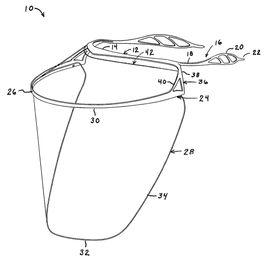
[0038] FIG. 1 is a perspective view of a face shield according to an
embodiment of the present invention and shown with an upper tier retention
frame member joined to a lower tier shield frame member to which are joined
a transparent face shield and an optional semitransparent minishield.
[0039] FIG. 2 is side view of the face shield shown in FIG. 1.
[0040] FIG. 3 is a perspective view of the face shield of FIG. 1 shown for
2o clarity without the transparent shield or minishield attached.
[0041] FIG. 4 is a top view of the face shield of FIG. 3.
[0042] FIG. 5 is a exploded side view of the face shield of FIG. 4, shown with
optional nose bridge member prior to be joined to the retention frame.
[0043] FIG. 6 through FIG. 9 are side views of support arm configurations
25 according to aspects of the present invention.
[0044] FIG. 10 is a side view of a two piece face shield, wherein the
retention
frame is attached prior to use to an inclined support connecting to the shield
frame member.
[0045] FIG. 11 is a perspective view of a face shield frame shown with locking
3o hinges according to another embodiment of the present invention.
[0046] FIG. 12 is a top view of a retention frame member according to another
embodiment of the present invention , shown configured for attachment of a
_$_
CA 02524570 2005-11-O1
WO 2004/098715 PCT/US2004/013763
shield frame member.
[0047] FIG. 13 is a top view of the retention member of FIG. 12, joined to a
face shield frame according to an aspect of the present invention.
[0048] FIG. 14 is a perspective view of face shield of FIG. 13 with attached
minishield.
[0049] FIG. 15 is a side view of the face shield of FIG. 14.
DETAILED DESCRIPTION OF THE INVENTION
[0050] Referring more specifically to the drawings, for illustrative purposes
the
present invention is embodied in the apparatus generally shown in FIG. 1
o through FIG. 15. It will be appreciated that the apparatus may vary as to
configuration and as to details of the parts, and that the method may vary as
to the specific steps and sequence, without departing from the basic concepts
as disclosed herein.
[0051] FIG. 1 through FIG. 5 exemplify a two tier face shield 10 according to
s an embodiment of the present invention. FIG. 1 and FIG. 2 provide views of
the assembled face shield 10 comprising upper retention frame member 12
having a central arcuate section 14 which extends rearwardly to support arms
16. The arc of curvature of the shield, frame member preferably has a radius
which exceeds that of the retention frame member, such as by a minimum of
2o approximately one half inch, wherein the shield member is retained away
from
the periphery of the face of the wearer by at least about one-half inch on
either side, wherein air may circulate to keep the face of the wearer cool and
dry while reducing the opportunity of the face shield to fog up. More
preferably, the radius of curvature of the shield frame member exceeds that of
25 the retention frame member by at least approximately three quarters of an
inch to approximately three inches.
[0052] To increase comfort while maintaining positive retention, the retention
frame member is preferably configured for positioning on the head of the
wearer at an angle so that the front of the retention frame member is raised
3o above the distal end of the support arms, such as a minimum of one quarter
inch (1l4 inch), or more preferably from about one half inch (1l2 inch) to
about
one and one half inches (1 °/2 inches). This is preferably measured
from the
_g_
CA 02524570 2005-11-O1
WO 2004/098715 PCT/US2004/013763
center of arc on the retention member in relation to the center of the distal
end
of the support arm.
[0053] The material of the frame members preferably comprises a
thermoplastic material which may be utilized with conventional molding
processes. Each support arm 16 extending from arcuate section 14 has a
proximal section 18. A webbed region 20 is shown near distal end 22. The
material in the webbed region is configured for applying pressure over narrow
distributed areas, preferably less than approximately one quarter inch wide or
more preferably less than one eighth inch wide, on the side of the head of the
1o wearer to assure secure retention, in which the face shield is prevented
from
sliding about. To distribute contact pressure in this manner, each support arm
is preferably adapted with an enlarged section 20, for example, a webbed
region in which one or more perimeters of material surround one or more
open regions. Preferably, a minimum of approximately one half square inch,
1s and more preferably an open area from approximately one square inch to
approximately three square inches, are provided within enlarged section 20 to
increase ventilation and distribute pressure.
[0054] A lower shield frame member 24 preferably has a central arcuate
section 26 to which is attached a transparent shield 20. It should also be
2o appreciated that shield frame member 24 may be manufactured according to
different geometric configurations, oval, rectangular, and so forth, without
departing from the teachings of the present invention. The transparent shield
may be attached permanently, semi-permanently, or temporarily to shield
frame member 24. To allow packaging the face shields at a higher density
2s (more compactly), such as nesting of the face shields, the lower shield
frame
member 24 can be designed with a fastener that can be manually activated,
such as after receipt by an end-user, to engage the transparent face shield.
Examples of the manually activated engagement means include snap-in
connectors, tabs, pins, fasteners, contact forms of adhesives (i.e. peeling a
so covering from adhesive area and applying), and so forth. By way of example,
the shield frame may include a first set of connectors which are configured to
engage a mating set of connectors on the transparent shield. These
-10-
CA 02524570 2005-11-O1
WO 2004/098715 PCT/US2004/013763
connectors preferably comprise protrusions extending from the shield frame
that engage and lock into apertures upon the transparent shield.
[0055] Shield frame 24 is preferably curved and positioned in separation from
the retention frame so as to provide clearance between the transparent shield
and the face of the wearer. It will be appreciated that the present tiered
design allows clearance to be incorporated not only at the front of the face
shield but also along the periphery of the face shield to increase ventilation
and reduce fogging.
[0056] Transparent shield member 28 has an upper edge 30, lower edge 32,
1 o and side edges 34, and preferably comprises a transparent flexible plastic
material, such as cut out from a sheet of plastic material. By way of example
and not limitation, preferred plastic materials include polystyrene, acrylic,
polyethylene, terephthalate, polycarbonate, equivalent polymeric materials, or
similar.
1s [0057] The retention frame member 12 is connected to the shield frame
member 24 by at least a pair of support members 36. preferably inclined
supports, each having an upper attachment structure 38 and lower attachment
structure 40, one or more of which preferably includes a webbed area to
increase support. These inclined support members 36 preferably comprise
2o more than one structural element to distribute the weight of the shield
frame
member and transparent shield, along with any forces that may be applied by
the wearer when the face shield is put on, taken off, or subject to occasional
loads during use (i.e. being bumped). Preferably, inclined support 36
comprises a webbed region having a perimeter that surrounds a section which
25 includes at least one open area having a minimum of approximately one
quarter square inch, and more preferably between approximately one half
square inch to approximately one square inch. By way of example, the
embodiment illustrates inclined support 36 connecting at a single location to
the retention frame member 12 and forking into two supports prior to
3o connection to the shield frame member 24.
[0058] Optionally joined above the shield frame member 24, is a minishield 42
which may comprise any shaded, semi-transparent to opaque material, for
-11-
CA 02524570 2005-11-O1
WO 2004/098715 PCT/US2004/013763
shading the eyes and protecting the upper face and head from flying material
debris. It should be appreciated that ventilation space exists above the
minishield and that the minishield may be manufactured of different shapes
and widths to provide a desired amount of shading and ventilation. Shield
frame member 24 may be adapted using any convenient means to receive
minishield 42 on the exterior or interior surfaces of arcuate section 26. By
way
of example minishield 42 may be attached such as with tape, locking pins,
hook-and-loop style fasteners, or other convenient permanent or temporary
mounting methods. Alternatively, minishield 42 may be permanently installed
1o along with the transparent shield 28, such as using adhesives, thermal
bonding techniques, permanent fasteners, and combinations thereof.
[0059] FIG. 3 through FIG. 5 illustrates the face shield framing with the
transparent shield and minishield removed from the structure for the sake of
clarity. Retention frame 12 depicting taper 44 is shown in FIG. 4 of support
1s arm 16 for providing sufficient pressure along support arms 16 to securely
retain the face shield on the head of the wearer. It should be noted that in
order to provide sufficient tension force with reduced material, the proximal
regions of support arms 16, nearing inclined support 36, are preferably formed
to have a horizontal width of material that is greater than the vertical depth
of
2o material. The widened section of support arm 16 is shown with optional
apertures 46, that can provide a decorative element while moderating the
amount of compliance within the support arms.
[0060] An optional nose bridge member 48 is shown in FIG. 5 with curving
bridge 50, vertical support 52, upper end 54, and which is preferably adapted
2s for engagement within a retention structure 56 of the retention frame
member
12. By way of example and not of limitation, engagement structure 56 may
comprise a snap socket engagement mechanism (shown) configured to
engage upper portion 50 of nose bridge 48. Alternatively, a narrowing slot
may be utilized to engage a flange on the upper portion of the nose bridge. It
so should be appreciated that nose bridge 48 may be alternatively attached by
any convenient method, including the use of mechanical retention, fasteners,
adhesives, and so forth. The use of nose bridge member 48 can improve
-12-
CA 02524570 2005-11-O1
WO 2004/098715 PCT/US2004/013763
face shield retention and positioning as a portion of the load of face shield
10
is supported upon the nose bridge of the wearer. Nose bridge member 48,
therefore, is either permanently joined or selectively joined, as a user
selected
face shield option, to the center of the retention frame member extending
downwardly from retention frame 12. The lower portion 50 of nose bridge
member 48 comprises a curving section configured for engaging the curving
surface on the bridge of the nose of said wearer. The interior of the curve on
nose bridge 48 may be configured with one or more pads with a view toward
increasing user comfort. It should be appreciated that utilizing a nose bridge
1o can be particularly beneficial if other equipment or elements are coupled
to
the face shield or frame which increase the weight being supported on the
head, for example attaching an examination light, or other equipment to the
face shield.
[0061] FIG. 6 through FIG. 9 depict support arms 16 having a number of
1s configurations within distributed contact sections 20. FIG. 6 illustrates
an
open web configuration 58 with narrow contact regions, which is a preferred
embodiment of the support arms. It should be appreciated that the use of
narrow contact regions disbursed over portions of the wearers' head are
generally less subject to sliding or other frame movement in relation to
broadly
2o distributing the contact forces. Preferably a webbed portion of the distal
end
of the support arms comprises a perimeter that surrounds a section which
includes a plurality of open regions, such as having an area of at least one
quarter square inch (1/4 sq, inch), or more preferably having at least one
open
area of at least one half square inch (1/2 sq. inch)
25 [0062 A number of other support arm configurations are depicted in the
following figures. FIG. 7 illustrates a logo webbing configuration 60. FIG. 8
illustrates a combination open webbing with logo configuration 62. FIG. 9
illustrates a slot configuration 64, into which, for example, a flow cell 66
may
be inserted to equalize the pressure applied by support arm 16 against the
so irregular surface of the head.
[0063 Optionally, materials may be applied to the interior of the face shield
where it contacts the head of the wearer. For example, compressible
-13-
CA 02524570 2005-11-O1
WO 2004/098715 PCT/US2004/013763
materials such as padding, closed or open cell foam, or the like could be
used.
[0064] FIG. 10 exemplifies a two piece face shield, wherein the retention
frame is attached prior to use to an inclined support connecting to the shield
frame member. A retention structure 68 is shown in the upper ends of the
inclined support for engaging a mating structure of retention frame member
12. It should be appreciated, however, that the face shield 10 may be
configured to provide separation between any one or more of the elements to
facilitate storage without departing from the teachings of the present
invention.
[0065] Packaging and storage space for the face shields may be reduced by
configuring the face shields as separate elements that are connected to the
frame elements prior to use, such as by the interlocking of engagement
structures to effect mechanical joining. The face shield preferably comprises
at least two separable elements. By way of example, a first portion comprises
a retention frame member which may be joined to a separate element
comprising the transparent shield attached to the shield frame member which
is attached to the inclined support members. The transparent shield may be
factory joined to the shield frame member 24, or may be semi-permanently, or
temporarily joined, such as by an end-user in preparation for use. It should
be
2o appreciated, however, that the face shield may be separated into more than
two elements, and that alternative groupings may be provided without
departing from the teachings of the present invention. For example, the
inclined support member may be alternatively permanently connected, such
as to the support frame member or configured as a separate element for
being joined between the support frame member and shield frame member.
[0066] FIG. 11 exemplifies a face shield frame which incorporates locking
hinge assemblies 70 for adjusting the contact pressure supplied by support
arms 16. The hinges may be disengaged to allow adjusting the positioning of
the support arms for secure retention and a comfortable fit. Although a
so number of support arm articulation mechanisms may be utilized, the
preferred
mechanisms are locking hinges as described in U.S. Patent No. 6,278,788
and U.S. Patent No. 6,016,808 both of which are incorporated herein by
-14-
CA 02524570 2005-11-O1
WO 2004/098715 PCT/US2004/013763
reference.
(0067] FIG. 12 through FIG. 15 illustrate another embodiment 90 of face shield
shown preferably configured with a separable shield frame member and
trampoline style support arms. FIG. 12 depicts a retention frame shown for
clarity without the shield frame support, while FIG. 14 and FIG. 15 depict an
attached minishield member but does not show the attachment of a
transparent shield.
[0068] in FIG. 12 a retention frame member 92 is shown having a central
arcuate section, from which support arms 94 extend rearwardly. The device is
1o shown configured with ventilated support arms 94, surrounding at least one
opening 96. The ventilated support arms are preferably configured in a
trampoline configuration having a three-dimensional webbed structure. It
should be appreciated that a three-dimensional trampoline web structure
provides advantages for both support and ventilation while reducing material
requirements. The three-dimensional structure for support arms 94 comprises
narrow compliant contact regions on the inside 98 of support arms 94 to make
secure contact with the head of the wearer while exterior rigid structures 100
support the compliant webbed material 98 on the inside. It will be appreciated
that the compliant regions 98 and rigid structures 100 may be formed of the
2o same material, such as within the same mold, but with different shapes and
structural cross sections.
[0069] A connection 102 provides a means of interconnecting a shield frame
to the retention frame 92. A recess 104 is shown with apertures 106 for
receiving connection pins. It should be appreciated that connection 102 may
be implemented utilizing any desired means of connecting retention frame 92
with a shield frame member. For example a taper fit connection may be
utilized, or alternatives such as post with barbs, snap-fit, and so forth.
[0070] The center arcuate section of retention frame 92 may also be
configured with removable support arms 94, that may join with retention frame
92 at the same location as the support frame is joined. For example, the oval
section 108 may depict a male connection of the end of a support arm 94 into
a matching female receptacle within retention frame 92. The shield support
-15-
CA 02524570 2005-11-O1
WO 2004/098715 PCT/US2004/013763
frame then interconnects to the support arms which are locked to the retention
frame. It will be appreciated that a number of alternative means for attaching
a shield frame element exist. The shield frame connection 102, and optional
support arm connection 108 are shown collocated at the position shown, by
s way of example and not of limitation, therefore it will be appreciated that
these
connections may be located along any portion of the retention frame.
[0071] A recess 110 is shown in the forward inner portion of retention frame
92 into which a cushion, such as a foam strip, or other form of forehead
interfacing element, may be joined.
[0072] In FIG. 13, shield frame element 112 is shown attached forward of the
center of retention frame 92 at connection 104. Retention frame 92 provides
for retaining a transparent shield element (not shown) away from the face of
the wearer, and preferably ventilation between the transparent shield and
retention frame 92. The shield frame element 112 preferably comprises an
arcuate lower edge 114 with inclined support members (drop arms) 116. A
means for attaching at least one transparent shield is shown exemplified as at
least one attach pin 118, which may also be referred to as a snap pin. The
edges of the transparent shield connect to inclined support members 116,
which are shown terminating in retention ovals 120 engaging recesses 108
2o within retention frame 92. A forehead interface member is depicted as a
strip
of foam 122 attached within recess 110 of retention frame 92. It will be
appreciated that the shield frame 90 is preferably held in place on the head
of
the wearer largely in response to forces applied at the forehead and behind
the ears by the ends of the support arms 94. Retention frame 92 is shown
configured with an inner shape that is preferably relieved in regions between
the ear and forehead, which results in increased comfort because circulation
is not impeded in that vascular region.
[0073] FIG. 14 and FIG. 15 depicts a face shield frame 90 with minishield
member 124 retained by attach pins 118 (not shown in FIG. 14, 15) and
so preferably engaged with inclined support members 116 on shield frame
member 114. Attachment pins are preferably located in at least three
locations along the periphery of shield frame member 114. The attachment of
-16-
CA 02524570 2005-11-O1
WO 2004/098715 PCT/US2004/013763
minishield 124 to a separate shield frame 114 provides beneficial ventilation
space 126, which is preferably unobstructed, through which humid air rising
from the wearers face can exit the face shield.
[0074] Inclined support members 116 are shown bifurcated and surrounding
s open area 128, which increases support without unduly increasing material
weight. Design elements, logos and indicias may be additionally, or
alternatively included within the area depicted as open area 128.
[0075] The elements of the face shield may be fabricated in any convenient
process and material, with the use of thermoplastic materials and a molding
1o process being generally preferred.
[0076] Accordingly, it will be seen that this invention provides for the
manufacture of a lightweight face shield device providing distributed
retention
pressure and ventilation between the transparent shield and the face of the
wearer, as well as between the frame members and the head. An
1s embodiment of the present invention has been depicted by way of example,
with a few contemplated variations and options. It should be appreciated,
however, that elements of the invention such as the shape or structure of the
frames and support arms and so forth, may be implemented in a number of
alternative ways by one of ordinary skill in the art without departing from
the
2o teachings of the present invention.
[0077] Although the description above contains many details, these should not
be construed as limiting the scope of the invention but as merely providing
illustrations of some of the presently preferred embodiments of this
invention.
Therefore, it will be appreciated that the scope of the present invention
fully
25 encompasses other embodiments which may become obvious to those skilled
in the art, and that the scope of the present invention is accordingly to be
limited by nothing other than the appended claims, in which reference to an
element in the singular is not intended to mean "one and only one" unless
explicitly so stated, but rather "one or more." All structural, chemical, and
so functional equivalents to the elements of the above-described preferred
embodiment that are known to those of ordinary skill in the art are expressly
incorporated herein by reference and are intended to be encompassed by the
-17-
CA 02524570 2005-11-O1
WO 2004/098715 PCT/US2004/013763
present claims. Moreover, it is not necessary for a device or method to
address each and every problem sought to be solved by the present invention,
for it to be encompassed by the present claims. Furthermore, no element,
component, or method step in the present disclosure is intended to be
dedicated to the public regardless of whether the element, component, or
method step is explicitly recited in the claims. No claim element herein is to
be construed under the provisions of 35 U.S.C. 112, sixth paragraph, unless
the element is expressly recited using the phrase "means for."
-18-