Note: Descriptions are shown in the official language in which they were submitted.
CA 02528976 2008-02-27
ABSORBENT TOWEL WITH PROJECTIONS
BACKGROUND
Strength and coordination exercises are becoming increasingiy more popufar
these days. Within heaith-conscious cuitures, sports such as~ jogging,
swimming
and bicyciing have long been common forms of exercise. More recentiy, however,
those desiring to stay in shape are seeking different, more innovative ways to
achieve or maintain a desired levet of physicat conditioning and mental
heaith,
while at the same time trying to decrease the incidence of injuries due to
high
impact exercising.
For exampie, various forms of yoga have gained greater acceptance within
today's society. Yoga is known to Increase strength and flexibiiity, whiie
reiaxing
the mind through focusing on holding certain body positions. Consequentiy,
yoga
and other similar discipiines can provide participants with an increased
fitness level
and improved state of mind. Typicaliy, cushioned rubber mats are used by those
i
CA 02528976 2005-12-09
WO 2005/007245 PCT/US2004/021475
who practice yoga for providing a soft surface for kneeling, standing, and
lying
down. However, due to the physical demand of balancing while holding various
poses for extended periods of time, the participants can perspire onto the
mats,
causing the mats to become slick, thereby increasing the likelihood of a
slipping
injury. Thus, the participant can become distracted from proper focus during
the
practice of yoga. Further, the mats are generally relatively non-absorbent,
and ofFer
few benefits other than creating a padded area for use by the yoga
participants.
SUMMARY
The present invention is directed to a towel that includes a base layer and a
plurality of raised projections that project away from the base layer. The
base layer
has a first side and a second side. In one embodiment, the projections can be
discontinuously positioned and can each be separately secured to one or both
of
the sides of the base layer. In one embodiment, the projections have a higher
coefficient of static friction than the base layer to inhibit relative
movement between
the towel and a surface upon which the towel is placed when the projections
are in
contact with the surFace.
In one embodiment, the base layer is formed from a liquid-absorbing
material such as a microfiber fabric material. Further, at least some of the
projections are formed at least partially from a relatively non-absorbent
latex
material. In on embodiment, the projections cover less than approximately 50
percent of one of the sides of the base layer. Moreover, in one particular
embodiment, at least some of the projections are substantially hemispherical
in
shape.
The present invention also includes a method for manufacturing a towel.
BRIEF ESCRIPTION OF 1'HE RAWI~~GS
The novel features of this invention, as well as the invention itself, both as
to
its sfiructure and its operation, will be best understood from the
accompanying
drawings, taken in conjunction with the accompanying description, in which
similar
reference characters refer to similar parts, and in which:
2
CA 02528976 2005-12-09
WO 2005/007245 PCT/US2004/021475
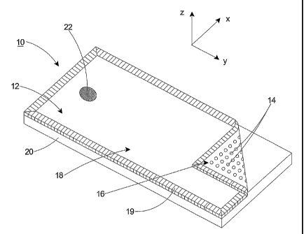
Figure 1 is a perspective view of one embodiment of a towel having features
of the present invention, shown in a first configuration;
Figure 2 is a partial plan view of a portion of another embodiment of the
towel having features of the present invention;
Figure 3A is a perspective view of a first embodiment of a projection;
Figure 3B is a side view of the projection illustrated in Figure 3A;
Figure 4A is a perspective view of a second embodiment of a projection;
Figure 4B is a side view of the projection illustrated in Figure 4A;
Figure 5A is a perspective view of a third embodiment of a projection;
Figure 5B is a side view of the projection illustrated in Figure 5A;
Figure 6A is a perspective view of a fourth embodiment of a projection;
Figure 6B is a side view of the projection illustrated in Figure 6A;
Figure 7 is a perspective view of another embodiment of a towel having
features of the present invention; and
Figure 8 is a perspective view of another embodiment of a towel having
features of the present invention, shown in a second configuration.
ESCRIPTI fV
Figure 1 is a perspective view of a towel 10 in a first, unrolled
configuration.
In this embodiment, the towel 10 includes a base layer 12 and a plurality of
raised
projections 14 that project away from the base layer 12 as described herein.
The
base layer 12 illustrated in Figure 1 has a first sid 16 and a second side
18. In this
embodiment, the projections 14 are secured to the first side 16. It is
recognized,
however, that either side 16, 18 can be the first side 16 or the second side
18. For
example, the projections 14 can be secured to the second side 18 of the base
layer
12. The towel 10 also includes a perimeter edge 19 that can be bound by any
generally acceptable manner Icnown to those skilled in the arl.
Figure 1 includes an orientation sysfiem that illustrates an X-axis, a Y-axis
that is orthogonal to the X-axis and a Z-axis that is orthogonal to the X- and
Y-axes.
It should be noted that these axes can also be referred to as the first,
second and
third axes, respectively, and that any of the axes can be the first, second or
third
axis.
3
CA 02528976 2005-12-09
WO 2005/007245 PCT/US2004/021475
In the embodiment illustrated in Figure 1, towel 10 can be placed on top of a
surface 20 that may otherwise become slick or slippery when moisture is
introduced
onto the surface 20. As shown in Figure 1, the surface 20 can be any suitable
type
of yoga or other sports mat, such as those including closed or open-cell foam,
for
use during yoga or other sporting exercises, as explained in greater detail
below.
Alternatively, the surface 20 can be any type of flooring material, a table or
other
furniture, the ground, or any other type of supporting surface.
The dimensions of the towel 10 can vary. The towel 10 can be sized to be
substantially similar to the surface 20 upon which the towel 10 is placed. In
one
embodiment, the towel 10 can have dimensions of approximately 24 inches by 68
inches, which are the approximate dimensions of a standard sized yoga mat 20.
However, the towel 10 can have dimensions larger or smaller than 24 inches by
68
inches. For example, in alternative embodiments, the towel 10 can be sized for
use
as a washcloth, a hand towel, a beach towel, a bath towel, a bath mat, a dish
towel,
a gym or sport towel, a drop cloth, a throw rug, or a baby changing mat, as
non-
exclusive examples.
Further, although the towel 10 is particularly suited for use as a non-
clothing
item, the towel 10 can be used in other applications where absorbency is
beneficial.
For instance, the towel 10 can be incorporafied into and/or manufacfiured for
use as
clothing, such as a bathrobe, a shirt, pants, a hat, a scarf, socks, or any
other
suitable clothing or non-clothing item. With this design, any moisture such as
perspiration, precipitation or incidental moisture can be absorbed by fihe
towel 10
as necessary.
The base layer 12 can be formed from relatively absorbent materials that
can vary depending upon the design requirements of the towel 10. For instance,
the base layer 12 can include any suitably absorbent natural fibers or
fabrics, such
as cotton, silk, wool, hemp, etc., and/or synthetic materials such as
acrylics,
polyester microfiber, nylon and/or rayon, as non-exclusive examples.
Further, fihe base layer 12 can have a wide range of thicicnesses, weights
and/or densities depending upon the absorbency and/or specific usage
requirements of the towel 10. The base layer 12 can also include different
colored
materials and/or different colored patterns, images and the like.
For exampl , in the embodiment illustrated in Figure 1, the second side 18 of
the base layer 12 includes a focal region 22 having a color that is different
than
substantially the remainder of the base layer 12. With this design, an
individual
4
CA 02528976 2005-12-09
WO 2005/007245 PCT/US2004/021475
performing yoga, martial arts or other sporting activities can focus his or
her
attention on the focal region 22 to assist with concentration and/or focus
during
participation in such exercises. The focal region 22 can be formed from the
same
material used to form the remainder of the base layer 12, or the focal region
22 can
be formed from a different material. In the embodiment illustrated in Figure
1, the
focal region 22 is somewhat disc-shaped and is sized small enough to allow the
user to focus on the focal region 22 without substantial movement of the
user's
eyes during exercise. For example, the focal region 22 can be between
approximately 1.0 centimeter and 6.0 centimeters in diameter. However, the
size of
the focal region 22 can be outside this range. In alternative embodiments, the
focal
region 22 can have any other suitable configuration, i.e. rectangular,
triangular,
linear, oval or another appropriate geometry.
The material(s) used for the projections 14 can be varied. For example, the
projections 14 can be formed from a substantially non-absorbent material such
as
various forms of plastic (e.g., latex), rubber, epoxy, or any other suitable
material,
as non-exclusive examples. The material used to form the projections 14 can
have
a relatively high coefficient of static friction. In one embodiment, the
material used
to form the projections 14 can have a coefficient of static friction that is
greater then
a coefficient of static friction of the base layer 12. With this design, fihe
relatively
high static friction of the projections 14 decrease the likelihood that the
towel 10 will
slip, slide or otherwise move relative to the surface 20 upon which the towel
10 is
positioned. Stated another way, the projections 14 provide greater traction
between fihe towel 10 and the surface 20.
The positioning, shape and size of the projections 14 can vary. In one
embodiment, the projections 14 are positioned in a pattern. For example, in
the
embodiment illustrated in Figure 1, the projections 14 are positioned in a
grid-like
arrangement on the base layer 12. In this embodiment, the projections 14 are
positioned in a plurality of substantially similar rows, each with a
relatively
consistent spacing between rows and between individual projections 14.
Alternatively, the projections 14 can be positioned in a substantially random
manner on the base layer 12.
Further, in the embodiment illustrated in Figure 1, each projection 14 is
separately secured to the first side 16 of the base layer 12 in an intermitt
nt,
unconnected and/or discontinuous manner. In one embodiment, the projections 14
can be secured to the base layer 12 by using a heat treatment method, which
can
CA 02528976 2005-12-09
WO 2005/007245 PCT/US2004/021475
include melting the projections 14 into position on the base layer 12.
Examples of
alternative methods that can be used to secure the projections 14 to the base
layer
12 include chemical bonding, adhesive, or any other suitable means, although
these methods are not intended to be limiting in any manner.
Because of the spacing between adjacent projections 14, the base layer 12
can more readily absorb moisture from the surface 20 and/or the user, with
reduced
or no interFerence by the projections 14. Stated another way, any inhibition
of
moisture absorption caused by the projections 14 is reduced or eliminated
because
a substantially portion of the first side of the base layer 12 is still
exposed,
notwithstanding the quantity of projections 14 secured to the base layer 12.
For
example, in one embodiment, the projections 14 are sized, shaped and
positioned
to cover less than approximately 20% of the total area of the base layer 12.
In
alternative embodiments, the projections 14 are sized, shaped and positioned
to
cover less than approximately 25%, 30%, 40%, 50%, 75% or 90% of the total area
of the base layer 12.
In still an alternative embodiment, two or more of the projections 14 can be
continuous, e.g. secured together on the base layer 12 to form lines, curves
or
other patterns on the base layer 12. IVloreover, in one embodiment, each of
the
projections 14 can be symmetrical relative to two or more axes. For example,
in
the embodiment illustrated in Figure 1, the projections 14 are symmetrical
relative
to three axes: the X-axis, the Y-axis and the Z-axis. In another embodiment,
the
projections 14 are symmetrical relative to two different axes, such as the X-
axis and
the Y-axis, although the particular axes about which the projections 14 are
symmetrical can vary. With these designs, the manufacturing process is
facilitated
and the tactile stimulus of the user is enhanced, as set forth in greater
detail below.
The spacing between the projections 14 can vary. In one embodiment, the
spacing of the projections 14 can be approximately one-quarier inch on center.
However, the spacing between the projections 14 can be greater or less than
one-
quarfier inch on center achieve the desired level of inhibition of movement
between
the projections 14 (and thus the base layer 12) and the surface 20.
Additionally,
because the projections 14 can be positioned relatively close to one another
while
not unduly inhibiting moisture absorption by the base layer 12, there is less
chance
for the base layer 12 to move, e.g., between the projections 14, relative to
the
surface 20. Consequently, injuries caused by slippage of the towel 10 relative
to
the surface 20 are reduced.
6
CA 02528976 2005-12-09
WO 2005/007245 PCT/US2004/021475
Further, the distance that each of the projections 14 projects or extends
away from the base layer 12 can vary. For instance, in one embodiment, the
projections 14 can project at least approximately 0.1 millimeters away from
the first
side 16 of the base layer 12. In alternative embodiments, the projections 14
can
project at least approximately 0.2 millimeters, 0.3 millimeters, 0.5
millimeters, 0.75
millimeters, 1.0 millimeters, 1.5 millimeters, 2.0 millimeters, 3.0
millimeters or 5.0
millimeters away from the first side 16 of the base layer 12.
In alternative embodiments, the projections 14 can project within the range
of (i) greater than 0.1 millimeters and less than 5.0 millimeters, (ii)
greater than 0.2
millimeters and less than 2.0 millimeters, or (iii) greater than 0.5
millimeters and
less than 1.0 millimeter away from the first side 16 of the base layer 12.
Still
alternatively, the projections 14 can project less than or greater than the
foregoing
distances and ranges away from the first side 16 of the base layer 12.
Moreover,
depending upon the spacing of the projections 14, the height of the
projections 14,
and/or the thickness and/or weight of the base layer 12, a user can receive
various
tactile sensations when in static or dynamic contact with the towel 10,
including
force on certain pressure points of the user's body or a massage of the
musculature
of the user, as non-exclusive examples. Vi/ith the foregoing designs, the user
can
receive the requisite level of tactile stimulus during usage of the towel 10.
Figure 2 is a partial plan view of an alternative embodiment of the towel 210.
In this embodiment, the projections 214 are positioned in a repeated, somewhat
diamond-shaped pattern on the base layer 212 so that the rows are somewhat
staggered from those illustrated in Figure 1. Still alternatively, the
projections 214
can be separately positioned to form concentric circles, triangles, or any
other
suitable geometric patterns.
Figures 3A-613 show various representative shapes of several embodiments
of the projections 14. The embodiments depicted in Figures 3A-613 are provided
for
convenience of discussion only, and are not intended to limit the scope of the
present invention in any manner. The shape of the projections 14 can vary
depending upon th level of tactile stimulus desired by the user in contact
wifih the
towel 10, and/or the extent to which a higher level of friction is necessary
or desired
between the projections 14 and th surface 20.
Figure 3A is a top view of one embodiment of the shape of a projection 314.
In this embodiment, the projection 314 has a round or circular footprint.
Figure 3B
7
CA 02528976 2005-12-09
WO 2005/007245 PCT/US2004/021475
is a side view of the projection 314 illustrated in Figure 3A. Figure 3B shows
that
the projection 314 can have a substantially dome or hemispherical shape.
Figure 4A is a top view of one embodiment of the shape of a projection 414.
In this embodiment, the projection 414 has a rectangular footprint. Figure 46
is a
side view of the projection 414 illustrated in Figure 4A. Figure 4B shows that
the
projections 414 have a substantially frusto-pyramidal shape.
Figure 5A is a top view of one embodiment of the shape of a projection 514.
In this embodiment, the projection 514 has a round or circular footprint.
Figure 4B
is a side view of the projection 514 illustrated in Figure 5A. Figure 5B shows
that
the projection 514 can have a substantially cylindrical, planar or flat shape.
Figure 6A is a top view of one embodiment of the shape of a projection 614.
In this embodiment, the projection 614 has a round or circular footprint.
Figure 6B
is a side view of the projection 614 illustrated in Figure 6A. Figure 6B shows
that
the projection 614 can have a substantially frusto-conical shape.
Figure 7 is an alternative embodiment of a towel 710. In this embodiment,
the towel 710 includes a plurality of first projections 714A on each of the
first side
716 of the base layer 712, and a plurality of second projections 714B the
second
side 718 of the base layer 712. 1lVith this design, the towel 710 can be used
with
either side 716, 718 facing downward (toward a surface 720) or upward (away
from
the surface 720). Further, the user can feel an increase in the tactile
stimulation
depending upon the quantity, shape, size and positioning of the projections
714A,
714B secured to the base layer 712 of the towel 710. The projections 714A,
714B
can be substantially the same shape, size and positioning on both sides 716,
718,
or the shape, size and positioning can differ from the first side 716 to the
second
side 718.
Figure 8 illustrates an embodiment of the towel 810 in a second, rolled-up
configuration. In this embodiment, the towel 810 can be substantially similar
to
those previously described. However, the towel 810 can also include a strap
824
that is removably or fixedly attached to the base layer 812. The strap 824 can
be
attached to the base layer 812 by any suitable means, including loop and pile,
hook
and loop, snaps, etc. Alternafiively, the strap 824 can be tied around the
base layer
812 to maintain the towel 810 in the rolled-up configuration. The strap 824
can
include a handle 826 for more easily carrying or otherwise transporting the
towel
810 between locations. Further, the strap 824 can be used for maintaining the
8
CA 02528976 2005-12-09
WO 2005/007245 PCT/US2004/021475
towel 810 in the second, rolled up configuration (as illustrated in Figure 8),
e.g. for
storage, until the towel 810 is ready for use.
While the particular towel 10 as herein shown and disclosed in detail is fully
capable of obtaining the objects and providing the advantages herein before
stated,
it is to be understood that it is merely illustrative of some of the presently
preferred
embodiments of the invention and that no limitations are intended to the
details of
construction or design herein shown other than as described in the appended
claims.
9