Note: Descriptions are shown in the official language in which they were submitted.
CA 02529276 2005-12-08
Attorney Docket No. 075169-9093
DRILL TEMPLATE
BACKGROUND
[0001] The present invention relates to a drill template for locating a
position for a hole in
a member.
[0002] It is known to use a template to quickly and accurately locate a
position for a hole
to be drilled in a member. The template can be used to quickly locate the
position for the
hole by aligning the template with the member, then marking the location for
the hole. The
template can be utilized to minimize the measurements that are taken by a user
to locate the
position for the hole. Measuring the position for the hole can be time
consuming, especially
when locating several holes at similar positions on multiple members.
Furthermore, the user
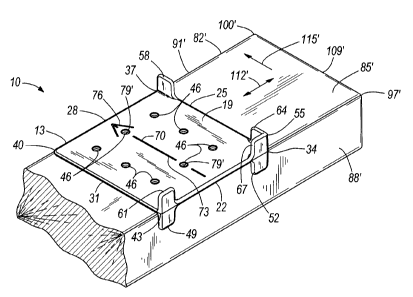
can make mistakes when measuring the location for the hole. The template can
provide
consistent results that minimize the chance of the user incorrectly
determining the position
for the hole.
SUMMARY
[0003] The invention provides an improved drill template. In one embodiment,
the
invention provides a drill template that is operable to locate a position for
a hole in a member
that has at least two distinct surfaces. The drill template comprises a body
that has first and
second oppositely-facing sides configured for locating a position for a hole
to be drilled in the
member. A first alignment member on the first side is configured to align with
both a first
surface and a second distinct surface of the member to position the body
relative to the
member. A second alignment member on the second side is configured to align
with the first
surface of the member by not with the second surface of the member to position
the body
relative to the member.
[0004] In another embodiment the invention provides a method of using a drill
template
that is operable to locate a position for a hole in a surface of a member. The
surface of the
member has opposite ends defined by corners of the member. The drill template
includes a
body that has first and second oppositely-facing sides, a first alignment
member on the first
side, and a second alignment member on the second side. The method comprises
determining
1
CA 02529276 2005-12-08
Attorney Docket No. 075169-9093
a location for the hole in the surface of the member. When the hole is to be
located adjacent
one of the opposite ends, the first alignment member is aligned with a corner
of the member
at one of the opposite ends of the surface to locate a position for the hole.
When the hole is to
be spaced from the opposite ends, the second alignment member is aligned with
an edge of
the member and spaced from the corners to locate a position for the hole.
[0005] Other aspects of the invention will become apparent upon consideration
of the
detailed description and accompanying drawings.
BRIEF DESCRIPTION OF THE DRAWINGS
[0006] Fig. I is a perspective view of a drill template in a first orientation
and spaced
from a member.
[0007] Fig. 2 is a perspective view of the drill template in the first
orientation and aligned
with the member.
[0008] Fig. 3 is a perspective view of the drill template in a second
orientation and spaced
from a member.
[0009] Fig. 4 is a perspective view of the drill template in the second
orientation and
aligned with the member of Fig. 3.
[0010] Fig. 5 illustrates an assembly formed from the two members of Figs. 1-
4.
[0011] Before any embodiments of the invention are explained in detail, it is
to be
understood that the invention is not limited in its application to the details
of construction and
the arrangement of components set forth in the following description or
illustrated in the
following drawings. The invention is capable of other embodiments and of being
practiced
or of being carried out in various ways. Also, it is to be understood that the
phraseology and
terminology used herein is for the purpose of description and should not be
regarded as
limiting. The use of "including," "comprising," or "having" and variations
thereof herein is
meant to encompass the items listed thereafter and equivalents thereof as well
as additional
items. Unless specified or limited otherwise, the terms "mounted,"
"connected,"
"supported," and "coupled" and variations thereof are used broadly and
encompass both
2
CA 02529276 2005-12-08
Attorney Docket No. 075169-9093
direct and indirect mountings, connections, supports, and couplings. Further,
"connected"
and "coupled" are not restricted to physical or mechanical connections or
couplings.
DETAILED DESCRIPTION
[0012] Figs. 1- 4 illustrate a drill template 10 including a body 13 with a
first side 16
(see Figs. I and 2) and an oppositely facing second side 19 (see Figs. 3 and
4). The
illustrated body 13 is a square, approximately 3'/z inches by 3'/2 inches, and
the body 13 is
generally planar and thin in cross section. Edges 22, 25, 28, 31 of the body
define corners 34,
37, 40, 43. The illustrated body 13 is only one possible construction, and it
should be
understood that the body 13 can be any suitable shape, such as circular,
rectangular, or
triangular and can be any suitable size. The body 13 can be made from plastic
or any suitable
material, such as steel, aluminum, wood, or composite. The body 13 can be
formed by
molding, stamping, casting, forging, cutting, or any suitable forming
technique. The
illustrated body 13 is molded plastic.
[0013] A plurality of apertures 46 extend through the body 13. While the
illustrated
apertures 46 are 3/16 inch holes, it should be understood that the apertures
46 can be any
suitable shape and size. In one construction, the apertures 46 are integrally
formed with the
body 13 when the body 13 is molded. In other constructions, the apertures 46
can be formed
after the body 13 is formed by drilling, stamping, or punching. The apertures
46 are located
on the body 13 in an arrangement specific to the particular application for
which the drill
template 10 is designed. Therefore, the location, as well as the number of the
apertures 46 on
the body can vary.
[0014] Referring to Fig. 1, the first side 16 of the body 13 includes an
alignment member
49 located adjacent to the corner 43 and an alignment member 52 located
adjacent to the
corner 34. While the illustrated alignment member 49 is adjacent to the corner
43 and the
illustrated alignment member 52 is adjacent the corner 34, in other
constructions the
alignment members 49, 52 can be located at any position along the edge 22 such
that the
alignment members 49, 52 are not adjacent the corners 34, 43. In yet other
constructions, the
alignment members 49, 52 can be consolidated into a single alignment member
with no space
therebetween.
3
CA 02529276 2005-12-08
Attorney Docket No. 075169-9093
[0015] The illustrated alignment members 49, 52 are projections that extend
outwardly
from and substantially normal to the body 13, are generally planar and are
orientated
generally parallel to each other. While the illustrated alignment members 49,
52 are
projections, it should be understood that the alignment members 49, 52 can be
any suitable
alignment member, such as a tab, marked or embossed lines, other markings or
apertures.
The illustrated alignment members 49, 52 are also generally flush with the
edge 22. In an
alternative construction, the edge 22 can extend beyond the alignment members
49, 52, such
that the alignment members 49, 52 are not generally flush with the edge 22.
[0016] Referring to Fig. 3, the second side 19 of the body 13 includes
alignment members
55, 58, 61. The alignment members 55, 58, 61 are projections that extend
outwardly from
and substantially normal to the body 13. While the illustrated alignment
members 55, 58, 61
are projections, it should be understood that the alignment members 55, 58, 61
can be any
suitable alignment member, such as tabs, marked or embossed lines, other
markings or
apertures. The illustrated alignment members 55, 58, 61 are generally flush
with the
respective edges 22, 25. In an alternative construction, the edges 22, 25 may
extend beyond
the alignment members 55, 58, 61, such that the alignment members 55, 58, 61
are not
generally flush with the respective edges 22, 25.
[0017] The illustrated alignment member 55 is located adjacent the corner 34
and
includes two portions 64, 67. The first portion 64 is parallel with the edge
25 and the second
portion 67 is parallel with the edge 22. The two portions 64, 67 are coupled
or intersect to
form substantially a 90 degree angle therebetween. The illustrated alignment
member 58 is
generally planar, is located adjacent the corner 37 and is parallel with the
edge 25. The
illustrated alignment member 61 is generally planar, is located adjacent the
corner 43 and is
parallel with the edge 22, such that the alignment members 58, 61 are
orientated generally
normal to each other. While the illustrated alignment members 58, 61 are
located adjacent
the respective corners 37, 43, it should be understood that the alignment
member 58 can be
located anywhere along the edge 25 and the alignment member 61 can be located
anywhere
along the edge 22. In one construction, the second side 19 may only include
the alignment
members 58 and 61. In other constructions, the second side 19 may only include
the
alignment member 55, or the alignment member 55 and only one of either the
alignment
members 58 or 61.
4
CA 02529276 2005-12-08
Attorney Docket No. 075169-9093
[0018] An indicia 70 is located on the second side 19 of the body 13. The
illustrated
indicia 70 includes a line 73 with an arrowhead 76, but may include any
suitable marking or
aperture. The illustrated line 73 defines an axis that extends through one or
more of the
apertures 46. The purpose of the indicia 70 will be discussed further below.
[0019] In one construction, the alignment members 49, 52, 55, 58, 61 and the
indicia
member 70 can be integrally formed with the body 13 during a stamping or
molding process.
In such a construction, the alignment members 49, 52, 55, 58, 61 and the body
13 can be
integrally molded from plastic or formed from metal as a single piece. In
other constructions,
the alignment members 49, 52, 55, 58, 61 can be separate pieces coupled to the
body 13, and
can be formed from any suitable material, such as wood, steel, plastic,
aluminum or
composite.
[0020] Referring to Fig. 1, the drill template 10, in a first orientation, is
configured to
locate positions for holes 79 to be drilled in a member 82. The illustrated
member 82
includes surfaces 85, 88, 91 that have ends defining corners 97, 100. The
corners 97, 100
partially define an end surface 109 of the member 82. The member 82 also
includes an
opposite end surface that is similarly defined in part by the ends of the
surfaces 85, 88, 91.
While the illustrated member 82 is a standard 2 inch x 4 inch wood board, it
should be
understood that the member 82 can be formed from any suitable material in any
suitable
dimension. For example, in other constructions, the member may be steel,
aluminum,
composite or plastic member of varying size.
[0021] Referring to Fig. 2, when the positions for the holes 79 are to be
located adjacent
the end surface 109, the drill template 10 is placed on the member 82 in the
first orientation,
such that the second side 19 of the drill template 10 directly faces and
engages with the
surface 85 of the member 82. The alignment member 58 is aligned with the
surface 88 of the
member 82 and the alignment member 61 is aligned with the end surface 109 of
the frame
member 82. The alignment member 55 is configured to receive and align with the
corner 97
such that the first portion 64 aligns with and engages the surface 88 and the
second portion 67
aligns with and engages the surface 109. When the drill template 10 is in the
position
illustrated in Fig. 2, the alignment members 55, 58, 61 prevent movement of
the drill
template 10 in the direction indicated by the arrows 112 and 115. This enables
the user to
accurately and intuitively locate the position for the holes 79 relative to
the member 82. A
marking device, such a pencil, pen, or a sharp object can then be inserted
through any number
CA 02529276 2005-12-08
Attorney Docket No. 075169-9093
of the apertures 46 to mark the member 82 to locate the position of the holes
79 that will be
drilled in the member 82. The number of holes 79 that are located depends on
the particular
application. In one application only one hole 79 may be marked, and in other
applications,
several holes 79 can be marked. After the holes 79 are marked, the drill
template can be
removed and the holes 79 are drilled into the member 82. Alternatively, the
drill template 10
could be left in place, as illustrated in Fig. 2, and used as a guide to drill
the holes 79.
[0022] Referring to Fig. 3, in a second orientation, the drill template 10 is
configured to
locate positions for holes 79' in a member 82'. The illustrated member
includes surfaces 85',
88', 91' that have ends defining corners 97', 100'. The corners 97', 100' at
least partially
define an end surface 109' of the member 82'. The member 82' also includes an
opposite end
surface that is similarly defined in part by the ends of the surfaces 85',
88', 91'. While the
illustrated member 82' is a standard 2 inch x 4 inch wood board, it should be
understood that
the member 82' can be formed from any suitable material in any suitable
dimension. For
example, in other constructions, the member may be steel, aluminum, composite
or plastic of
varying size. While the illustrated member 82' is substantially similar to the
member 82 of
Figs. 1 and 2, it should be understood that the member 82' could be different
from the
member 82.
[0023] As illustrated in Figs. 3 and 4, when the positions for the holes 79'
are to be
spaced from the end surface 109', the drill template 10 is placed on the
member 82' in the
second orientation. In the second orientation, the drill template 10 is
configured to locate the
positions for the holes 79' at any distance 118 from the end surface 109' of
the member 82'.
To locate the desired positions for the holes 79', the desired distance 118 is
measured from
the end surface 109' and a mark 121 is made on the surface 85' to locate the
positions for the
holes 79' with respect to the end surface 109'. Then, the drill template 10 is
placed on the
member 82' such that the first side 16 of the drill template 10 directly faces
and engages with
the surface 85' of the member 82'. The alignment members 49 and 52 are aligned
with the
surface 88, which defines an edge of the member 82. As illustrated in Fig. 3,
the arrowhead
76 can be used to generally align the indicia 70 with the mark 121 prior to
engaging the drill
template 10 with the surface 85'. Then, when the drill template 10 is in the
position as
illustrated in Fig. 4, the drill template 10 can be moved in the direction
indicated by the
arrows 112' to view the mark 121 through one of the apertures 46 to generally
align the line
73 of the indicia 70 with the mark 121.
6
CA 02529276 2005-12-08
Attorney Docket No. 075169-9093
[0024] With the drill template 10 in the second orientation as illustrated in
Fig. 4, the
alignment members 49 and 52 prevent movement of the drill template further in
the direction
indicated by the arrow 115', but the drill template 10 can still be moved
(e.g., sliding
movement along the surface 85') in the direction indicated by the arrows 112'.
This enables
the user to move the drill template 10 along the surface 85' while still
maintaining the
alignment provided by the engagement of the alignment members 49 and 52 with
the surface
88'. The marking device can then be inserted through any number of the
apertures 46 to
locate the positions of the holes 79' that will be drilled in the member 82'.
The number of
holes that are located can depend on the particular application of the drill
template 10 and it
should be understood that any number of holes can be located.
[0025] After the positions for the holes 79' are marked, the drill template 10
can be
removed from the member 82' and the holes 79' are drilled in the member 82'.
Alternatively,
the drill template 10 could be left in place, as illustrated in Fig. 4, and
used as a guide to drill
the holes 79'.
[0026] Fig. 5 illustrates an assembly 124 that can be formed using the drill
template 10
and the members 82 and 82' of Figs. 1- 4. The assembly 124 includes the frame
members
82, 82', a bracket 127, a plurality of first fasteners 130 (e.g., screws) and
a plurality of second
fasteners 133 (e.g., bolts). The illustrated bracket 127 includes bracket
apertures 136, 137,
and 139. The bracket apertures 136 and 137 are configured to receive the first
fasteners 130
and the bracket apertures 139 are configured to receive the second fasteners
133.
[0027] With continued reference to Fig. 5, the assembly 124 is formed by
placing bracket
127 on the surface 85' of the frame member 82' such that the bracket apertures
136 generally
align with the holes 79' in the member 82'. The holes 79' were located using
the drill
template 10 in the second orientation. The bracket apertures 137 are generally
aligned with
the holes 79 in the member 82. The holes 79 were located using the drill
template 10 in the
first orientation. While the illustrated holes 79 and 79' are blind holes that
are drilled about 1
inch into the respective members 82 and 82', in other constructions the holes
79 and 79' can
be through holes. The holes 79, 79' are drilled prior to inserting the first
fasteners 130 into
the members 82 and 82' to substantially prevent cracking of the members 82 and
82' when the
first fasteners 130 are inserted into the members 82 and 82. The first
fasteners 130 can then
be inserted through the bracket apertures 136, 137 and into the holes 79, 79'
to couple the
7
CA 02529276 2009-02-05
67363-1473
bracket 127 to the members 82 and 82', thereby
interconnecting the members 82 and 82'. Additionally, the
bracket apertures 139 can be used as a guide to drill holes
142 that receive the second fasteners 133. The second
fasteners 133 can then be inserted through the bracket
apertures 139 and into the holes 142 to provide further
support for coupling the bracket 127 to the members 82 and
82'. In other constructions, the drill template 10 can be
used to locate the positions for the holes 79 and 79' and
then the bracket apertures 137, 136 can be used as guides to
drill the respective holes 79, 79'. In yet other
constructions, the drill template 10 can be used to locate
the positions for the holes 79, 79' and 142.
[0028] Figs. 1-5 illustrate one application of the drill
template 10. In such an application, the drill template 10
can be included in a children's playstation kit, such as the
playstation kit described in U.S. Patent Application No.
2007/0062126 published on March 22, 2007. The drill
template 10 can be included with such a playstation kit,
along with instructions, to guide a user to locate positions
of holes in members used to form various assemblies, such as
the assembly 124 illustrated in Fig. S. However, it should
be understood that this is just one application of the drill
template 10. The drill template 10 can be utilized in any
application to locate a position for a hole to be drilled in
a member.
[0029] Thus, the invention provides, among other things,
a reversible drill template including two oppositely-facing
sides each configured for accurately and intuitively
locating a position for a hole to be drilled in a member.
8
CA 02529276 2009-02-05
67363-1473
[0030] Various features and advantages of the invention
are set forth in the following claims.
8a