Note: Descriptions are shown in the official language in which they were submitted.
CA 02535252 2006-02-07
DESCRIPTION
RECORDING POWER DETERMINATION METHOD AND DEVICE
TECHNICAL FIELD
[0001] The present invention relates to a recording power
determination method and a recording power determination
device for determining a recording power for recording data
on an information storage medium.
BACKGROUND ART
[0002] Optical discs are known as information storage
mediums for data recording. An optical disc apparatus
irradiates an optical disc with an optical beam to record
data or to reproduce data recorded on the optical disc. Even
if optical discs and optical disc apparatuses are produced in
the same manner, there are individual differences among the
optical discs and the optical disc apparatuses. Due to the
individual differences, there may occur a problem that data
cannot be properly recorded on an optical disc or data
recorded on an optical disc cannot be properly reproduced.
[0003] As one method for preventing such a problem, it is
1
CA 02535252 2006-02-07
known to determine a recording power which is appropriate for
an individual optical disc and an individual optical disc
apparatus when, for example, mounting an optical disc.
[0004] FIG. 16 is a schematic view showing a general
optical disc 601. As shown in FIG. 16, the optical disc 601
has a track 602 formed therein spirally. By irradiating the
track 602 with an optical beam having a modified recording
power, a plurality of marks and a plurality of spaces are
formed on the track 602. Thus, data is recorded. The
optical disc 601 includes a user data area used for data
recording by the user and a recording power determination
area used for determining a recording power of the optical
beam. The recording power determination area is provided in
an area other than the user data area (specifically, an
innermost area or an outermost area of the optical disc 601).
[0005] FIG. 17 is a schematic view showing a conventional
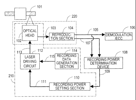
optical disc apparatus 700. The optical disc apparatus 700
includes an optical head 702, a reproduction section 704, a
demodulation/ECC (Error Correcting Code) circuit 706, a
recording power determination section 708, a recording power
2
CA 02535252 2006-02-07
setting section 710, a laser driving circuit 712, and a
recording data generation section 714.
[0006] When the optical disc 601 is mounted on the optical
disc apparatus 700, the type of the optical disc 601 is
identified, and the optical disc 601 is rotated. The optical
head 702 has a semiconductor laser (not shown). While being
rotated, the optical disc 601 is irradiated with an optical
beam emitted from the semiconductor laser of the optical head
702.
[0007] For recording data on the optical disc 601, the
optical head 702 irradiates the optical disc 601 with an
optical beam having a predetermined recording power to form
marks on the optical disc 601. In this example, data of the
Run Length Limited (1,7) modulation system is recorded by a
mark edge recording method. In this case, seven types of
marks and spaces are formed on the optical disc 601 on the
basis of reference cycle T, which is 2T at the shortest and
8T at the longest.
[0008] For reading data from the optical disc 601, the
optical head 702 irradiates the optical disc 601 with an
3
CA 02535252 2006-02-07
optical beam having a reproduction power which is smaller
than the recording power and receives light reflected by the
optical disc 601. The optical head 702 performs
optical/electric conversion on the received light to generate
a signal indicating the data recorded on the optical disc
601. The reproduction section 704 measures a modulation
factor of the signal generated by the optical head 702, and
digitizes the signal generated by the optical head 702. The
modulation factor will be described later with reference to
FIG. 19.
[0009] The demodulation/ECC circuit 706 demodulates the
signal digitized by the reproduction section 704 and corrects
errors. The recording power determination section 708
determines the recording power for recording the data based
on the modulation factor measured by the reproduction section
704. The recording power setting section 710 sets the
recording power determined by the recording power
determination section 708 in the laser driving circuit 712.
The recording data generation section 714 generates data to
be recorded on the optical disc 601. The laser driving
4
CA 02535252 2006-02-07
circuit 712 drives the optical head 702 to record the data
generated by the recording data generation section 714 on the
optical disc 601 at the recording power set by the recording
power setting section 710.
[0010] FIG. 18 is a schematic view showing the
reproduction section 704 in the conventional optical disc
apparatus 700. As shown in FIG. 18, the reproduction section
704 includes a preamplifier 801, a sampling and holding
circuit 802, an A/D converter 803, an arithmetic operator
804, and a binary data generation section 805.
[0011] The binary data generation section 805 digitizes
the signal generated by the optical disc 702 to generate
digitized data (binary data), and outputs a signal 705
indicating the binary data to the demodulation/ECC circuit
706 and the recording power determination section 708.
[0012] The preamplifier 801 amplifiers the signal
generated by the optical head 702. The sampling and holding
circuit 802 samples the signal amplified by the preamplifier
801 and holds the peak value and the bottom value of the
signal. The A/D converter 803 digitizes the peak value and
CA 02535252 2006-02-07
the bottom value held by the sampling and holding circuit
802. The arithmetic operator 804 performs an arithmetic
operation on the digitized peak value and bottom value to
obtain a modulation factor.
[0013] FIG. 19 is a schematic view showing a waveform of
the signal which is output from the preamplifier 801. As
shown in FIG. 19, the modulation factor is represented by (A
- B)/A, where amplitude A is the amplitude from the signal
level when no optical beam is emitted by the semiconductor
laser of the optical head 702, or the signal level when no
influence is exerted by the light reflected by the optical
disc 601 even though the optical disc 601 is irradiated with
an optical beam having a reproduction power emitted by the
semiconductor laser of the optical head 702, to the signal
level corresponding to the mark; and amplitude B is the
amplitude from the signal level when no optical beam is
emitted by the semiconductor laser of the optical head 702 to
the signal level corresponding to the space.
[0014] Returning to FIG. 17, a conventional recording
power determination method will be described.
6
CA 02535252 2006-02-07
[0015] On the optical disc 601, a constant parameter is
recorded to be used for determination of the recording power.
The optical head 702 generates a signal 703 indicating the
constant parameter (hereinafter, referred to as a
"predetermined value") read from the optical disc 601, and
outputs the signal 703 to the reproduction section 704. The
binary data generation section 805 of the reproduction
section 704 generates the binary signal 705 obtained by
binarizing the signal 703 indicating the predetermined value,
and outputs the signal 705 to the recording power
determination section 708.
[0016] The recording power setting section 710 sets a test
recording power of the optical beam in the laser driving
circuit 712. The recording power setting section 710 sets
eight different test recording powers A through H. In this
example, the test recording power A is the largest power, and
the test recording powers become smaller from the test
recording power B toward the test recording power H.
[0017] The recording data generation section 714 generates
test data, and outputs a signal 715 indicating the generated
7
CA 02535252 2006-02-07
test data to the laser driving circuit 712. The laser
driving circuit 712 drives the optical head 702 to record the
test data over substantially one circle of the track
continuously from a predetermined position in the recording
power determination area of the optical disc 601. The
recording data generation section 714 generates the test data
such that the optical head 702 continuously forms 8T marks
and 8T spaces on the optical disc 601. The test data is
repeatedly recorded over substantially one circle of the
optical disc 601 at the test recording powers A through H.
FIG. 20 shows areas of the optical disc 601 corresponding to
the test recording powers A through H with letters "A"
through "H".
[0018] When the recording of the test data is finished,
the optical head 702 irradiates the optical disc 601 with an
optical beam having a reproduction power. By this, the test
data recorded on the track is read, and a signal indicating
the test data is generated. The amplitude of the signal
generated by the optical head 702 changes in accordance with
whether or not the marks are formed on the optical disc 601.
8
CA 02535252 2006-02-07
The signal 703 generated by the optical head 702 is input to
the reproduction section 704.
[0019] Returning to FIG. 18, the preamplifier 801 of the
reproduction section 704 amplifies the signal 703. The
sampling and holding circuit 802 holds the peak value and the
bottom value of the signal amplified by the preamplifier 801.
The A/D converter 803 digitizes the peak value and the bottom
value of the signal held by the sampling and holding circuit
802. The arithmetic operator 804 performs an arithmetic
operation on the digitized peak value and bottom value to
obtain the modulation factor of the signal. Since the
amplitude of the signal 703 is different in accordance with
the test recording powers A through H, the modulation factor
is also different in accordance with the test recording
powers A through H. The arithmetic operator 804 generates a
signal 707 indicating the modulation factors of the signal,
and outputs the signal 707 to the recording power
determination section 708.
[0020] The recording power determination section 708
determines the recording power based on the modulator factors
9
CA 02535252 2006-02-07
corresponding to the test recording powers A through H by one
of two conventional recording power determination methods
described below.
[0021] FIG. 21 shows a view for describing a first
conventional recording power determination method, and is a
graph illustrating the relationship between the test
recording power and the modulation factor. According to the
first conventional recording power determination method, the
recording power determination section 708 selects a recording
power PO corresponding to a modulation factor MO based on the
correlation between the plurality of test recording powers
and a plurality of modulation factors corresponding to the
plurality of test recording powers. The recording power
determination section 708 calculates a product of the
recording power PO and a predetermined value read from the
optical disc 601 and thus determines the recording power used
for recording data. The recording power determination
section 708 outputs a signal 709 indicating the calculated
recording power to the recording power setting section 710.
[0022] FIG. 22 shows a view for describing a second
CA 02535252 2006-02-07
conventional recording power determination method, and is a
graph illustrating the relationship between (i) the test
recording power and (ii) the product of the modulation factor
and the recording power. According to the second
conventional recording power determination method, the
recording power determination section 708 calculates a
product of each of the plurality of test recording powers and
a modulation factor corresponding thereto, and thus creates
an approximate line indicating the correlation between
(i) the test recording power and (ii) the product of the
modulation factor and the test recording power. Then, the
recording power determination section 708 obtains a recording
power Pthr at which the product is 0 on the approximate line.
Next, the recording power determination section 708
calculates a product of the recording power Pthr and a
predetermined value read from the optical disc 601, and
'determines the recording power used for recording data. The
recording power determination section 708 outputs a signal
709 indicating the calculated value to the recording power
setting section 710.
11
CA 02535252 2006-02-07
DISCLOSURE OF INVENTION
PROBLEMS TO BE SOLVED BY THE INVENTION
[0023] However, an appropriate recording power cannot be
determined either by the first conventional recording power
determination method or the second conventional recording
power determination method.
[0024] In the case that the recording power determination
section 708 determines the recording power according to the
first conventional recording power determination method, the
recording power determination section 708 cannot determine an
appropriate recording power when, for example, there is a
relative tilt between the optical disc 601 and the optical
head 702. Hereinafter, with reference to FIG. 23, the
recording power when there is such a tilt will be described.
[0025] FIG. 23 is a graph illustrating the relationship
between the recording power and the modulation factor. In
the graph of FIG. 23, a solid line 1101 represents the result
obtained when there is no tilt at the time of data recording
or at the time of reading of the recorded data. A solid line
12
CA 02535252 2006-02-07
1102 represents the result obtained when there is a tilt at
the time of data recording, but there is no tilt at the time
of data reading. A solid line 1103 represents the result
obtained when there is a tilt both at the time of data
recording and at the time of data reading. The modulation
factor is smaller when there is a tilt than when there is no
tilt. In the case where there is no tilt at the time of data
reading but there is a tilt at the time of data recording,
the modulation factor corresponding to the recording power H,
which is smallest among the eight recording powers, cannot be
measured. Similarly, in the case where there is a tilt both
at the time of data recording and at the time of data
reading, the modulation factor corresponding to the recording
power H cannot be measured.
[0026] Test data is recorded and read before user data is
recorded. The test data is read immediately after being
recorded. Accordingly, when the test data is recorded and
read while there is a relative tilt, the result represented
by the solid line 1103 in FIG. 23 is obtained. When
determining the recording power by the ffirst conventional
13
CA 02535252 2006-02-07
recording power determination method, the recording power
determination section 708 selects a recording power P1103
corresponding to the modulation factor M0. This result is
influenced by the tilt at the time of test data recording and
also by the tilt when the test data is read (hereinafter,
referred to as "at the time of test data reading").
[0027] In the case where there is a tilt at the time of
test data recording, it is considered that there is a tilt
also at the time of user data recording. However, there is
not necessarily a tilt at the time of user data reading. It
is very rare that the user data is read immediately after
being recorded. In many cases, the user data is read by
another optical disc apparatus or after the optical disc is
re-mounted on the optical disc apparatus. Therefore, there
is no tilt at the time of user data reading. Accordingly,
for determining the recording power, only the influence of
the tilt at the time of test data recording needs to be
considered. It is not necessary to consider the influence of
the tilt at the time of test data reading. Therefore, the
recording power which should be selected when there is a
14
CA 02535252 2006-02-07
relative tilt is not the recording power P1103 but is a
recording power P1102 in FIG. 23. When determining the
recording power by the first conventional recording power
determination method, the recording power determination
section 708 selects the recording power P1103, which is
larger than the recording power P1102. Therefore, the
optical head 702 records data with an unnecessarily large
power. As a result, by the first conventional recording
power determination method, the optical disc 601 is
deteriorated unnecessarily quickly by repeated recording.
[0028] When using the second conventional recording power
determination method for determining the recording power, the
following occurs as shown in FIG. 24. When the recording
power determination section 708 selects four larger test
recording powers among the eight test recording powers and
creates an approximate line indicating the correlation
between (i) each of these four test recording powers and
(ii) the product of the modulation factor and each of these
four recording powers, the recording power at which the
product is 0 on the approximate line is the recording power
CA 02535252 2006-02-07
Pthrl. By contrast, when the recording power determination
section 708 selects four smaller test recording powers among
the eight test recording powers and creates an approximate
line indicating the correlation between (i) each of these
four test recording powers and (ii) the product of the
modulation factor and each of these four recording powers,
the recording power at which the product is 0 on the
approximate line is a recording power Pthr2.
[0029] As is clear from FIG. 24, the recording power at
which the product is 0 on the approximate line is
significantly different in accordance with the test recording
power. Namely, when determining the recording power by the
second conventional recording power determination method, the
recording power to be determined is significantly different
depending on the test recording power which is used for
recording the test data and depending on the test recording
power, the result of which is used for determining the
recording power. Accordingly, when using the second
conventional recording power recording method, the recording
power determination section 708 cannot uniquely determine an
16
CA 02535252 2006-02-07
appropriate recording power. In addition, when the recording
power determination section 708 determines a recording power
larger than an appropriate recording power, the optical disc
is deteriorated unnecessarily quickly. By contrast, when the
recording power determination section 708 determines a
recording power smaller than an appropriate recording power,
the data cannot be recorded properly on the optical disc.
[ 0030 ] The present invention , made in light of the above-
described problems, has an object of providing a recording
power determination method and a recording power
determination device for determining an appropriate recording
power.
MEANS FOR SOLVING THE PROBLEMS
[0031] A recording power determination method according to
the present invention, for determining a recording power of
an optical beam for recording data on an information storage
medium, comprises a test data recording step of recording
test data on the information storage medium at a plurality of
test recording powers; a modulation factor measuring step of
reading the test data recorded at each of the plurality of
17
CA 02535252 2006-02-07
test recording powers, generating a signal, and measuring a
modulation factor of the signal corresponding to each of the
plurality of test recording powers; a product obtaining step
of calculating a product of an n'th power of each of the
plurality of test recording powers and the modulation factor
corresponding thereto, thereby obtaining a plurality of
products corresponding to the plurality of test recording
powers , where n is a value of exponent and is a real number
other than 1; a first recording power calculating step of
calculating a first recording power based on the correlation
between the plurality of test recording powers and the
plurality of products; and a recording power calculating step
of calculating the recording power based on the first
recording power.
[0032] In one embodiment, the first recording power
calculating step includes the step of creating an approximate
line indicating the correlation between the plurality of test
recording powers and the plurality of products, and
calculates the first recording power at which the product is
0 on the approximate line.
18
CA 02535252 2006-02-07
[0033] In one embodiment, in the product obtaining step,
the value of exponent n is 2.
[0034] In one embodiment, the recording power
determination method further comprises a value reading step
of reading a value recorded on the information storage
medium. The information storage medium has a value of Pind,
a value of p and a value of K recorded thereon; the value
reading step includes the step of reading the value of Pind,
the value of p and the value of x; the test data recording
step includes the step of setting a range of the plurality of
test recording powers to be a range of 0.9 times to 1.1 times
the value of Pind; the first recording power calculating step
includes the step of creating an approximate line indicating
the correlation between the plurality of test recording
powers and the plurality of products, and calculating the
first recording power at which the product is 0 on the
approximate line; and the recording power calculating step
includes the step of calculating a product of the first
recording power, (-1/(the value of x) + 2) and the value of
P.
19
CA 02535252 2006-02-07
[0035] In one embodiment, the recording power
determination method further comprises a value reading step
of reading a value recorded on the information storage
medium. The information storage medium has the value of
exponent n recorded thereon; the value reading step includes
the step of reading the value of exponent n; and the product
obtaining step includes the step of using the read value of
exponent n.
[0036] In one embodiment, the test data recording step
includes the step of recording the test data such that the
signal generated in the modulation factor measuring step
includes a plurality of single cycle signals.
[0037] In one embodiment, the information storage medium
has a plurality of marks and a plurality of spaces formed
thereon by the optical beam which has been modulated; and the
test data recording step includes the step of forming the
plurality of marks such that an amplitude of the signal
generated in the modulation factor measuring step is
substantially the same as the amplitude of the longest mark
among the plurality of marks formed on the information
CA 02535252 2006-02-07
storage medium.
[0038] In one embodiment, the information storage medium
has a plurality of tracks concentrically or spirally formed
therein.
[0039] In one embodiment, the product obtaining step
includes the step of obtaining a plurality of products
corresponding to the plurality of test recording powers
regarding each of a plurality of values provided as the value
of exponent n; the recording power determination method
further comprises a value determining step of calculating a
linearity of the correlation between the plurality of test
recording powers and the plurality of products regarding each
of the plurality of values, thereby calculating a plurality
of linearities corresponding to the plurality of values, and
determining one of the plurality of values which corresponds
to the highest linearity; and the first recording power
calculating step includes the step of calculating the first
recording power using the plurality of products corresponding
to the plurality of test recording powers regarding the one
of the plurality of values which corresponds to the highest
21
CA 02535252 2006-02-07
linearity.
[0040] In one embodiment, the plurality of values include
a first value and a second value; and the first value is 2,
and the second value is 3.
[0041] In one embodiment, the recording power
determination method further comprises a value reading step
of reading a value recorded on the information storage
medium. The information storage medium has a value of Pind,
a value of p and a value of K recorded thereon; the value
reading step includes the step of reading the value of Pind,
the value of p and the value of x; the test data recording
step includes the step of setting a range of the plurality of
test recording powers to be a range of 0.9 times to 1.1 times
the value of Pind; and the first recording power calculating
step includes the step of creating an approximate line
indicating the correlation between the plurality of test
recording powers and the plurality of products, and
calculating the first recording power at which the product is
0 on the approximate line.
[0042] In one embodiment, the recording power calculating
22
CA 02535252 2006-02-07
step includes the steps of , in the case where the linearity
when the value of exponent n is 2 is higher than the
linearity when the value of exponent n is 3, calculating a
product of the first recording power, (-1/(the value of x) +
2) and the value of p; and in the case where the linearity
when- the value of exponent n is 3 is higher than the
linearity when the value of exponent n is 2, calculating a
product of the first recording power, (3 x (the value of
2)/(2 x (the value of K) - 1) and the value of p.
[ 0043 ] In one embodiment , the plurality of values include
a first value and a second value; and the value determining
step includes a first test recording power group setting step
of, regarding the first value, selecting at least two test
recording powers from the plurality of test recording powers,
and setting a first test recording power group including the
selected at least two test recording powers; a first gradient
calculating step of creating a first straight line based on
all the test recording powers included in the first test
recording power group and the products corresponding to all
the test recording powers included in the first test
23
CA 02535252 2006-02-07
recording power group, and calculating a first gradient of
the first straight line; a second test recording power
setting step of, regarding the first value, selecting at
least two test recording powers which are not completely the
same as the at least two test recording powers included in
the first test recording power group, from the plurality of
test recording powers, and setting a second test recording
power group including the selected at least two test
recording powers; a second gradient calculating step of
creating a second straight line based on all the test
recording powers included in the second test recording power
group and the products corresponding to all the test
recording powers included in the second test recording power
group, and calculating a second gradient of the second
straight line; a first ratio obtaining step of obtaining a
first ratio corresponding to the first value based on the
first gradient and the second gradient; a third test
recording power group setting step of, regarding the second
value, selecting at least two test recording powers from the
plurality of test recording powers, and setting a third test
24
CA 02535252 2006-02-07
recording power group including the selected at least two
test recording powers; a third gradient calculating step of
creating a third straight line based on all the test
recording powers included in the third test recording power
group and the products corresponding to all the test
recording powers included in the third test recording power
group, and calculating a third gradient of the third straight
line; a fourth test recording power group setting step of,
regarding the second value, selecting at least two test
recording powers which are not completely the same as the at
least two test recording powers included in the third test
recording power group, from the plurality of test recording
powers, and setting a fourth test recording power group
including the selected at least two test recording powers; a
fourth gradient calculating step of creating a fourth
straight line based on all the test recording powers included
in the fourth test recording power group and the products
corresponding to all the test recording powers included in
the fourth test recording power group, and calculating a
fourth gradient of the fourth straight line; a second ratio
CA 02535252 2006-02-07
obtaining step of obtaining a second ratio corresponding to
the second value based on the third gradient and the fourth
gradient; and a comparing step of comparing the first ratio
and the second ratio.
[0044] In one embodiment, the first test recording power
group setting step includes the step of selecting two largest
test recording powers among the plurality of test recording
powers; the second test recording power group setting step
includes the step of selecting two smallest test recording
powers among the plurality of test recording powers; the
third test recording power group setting step includes the
step of selecting two largest test recording powers among the
plurality of test recording powers; and the fourth test
recording power group setting step includes the step of
selecting two smallest test recording powers among the
plurality of test recording powers.
[0045] In one embodiment, the recording power
determination method further comprises the steps of
calculating a first average power indicating an average of
all the plurality of test recording powers regarding the
26
CA 02535252 2006-02-07
first value; and calculating a second average power
indicating an average of all the plurality of test recording
powers regarding the second value. The first test recording
power group setting step includes the step of selecting the
test recording powers to be included in the first test
recording power group from the plurality of test recording
powers, such that an average of the test recording powers
included in the first test recording power group is larger
than the first average power; the second test recording power
group setting step includes the step of selecting the test
recording powers to be included in the second test recording
power group from the plurality of test recording powers, such
that an average of the test recording powers included in the
second test recording power group is smaller than the first
average power; the third test recording power group setting
step includes the step of selecting the test recording powers
to be included in the third test recording power group from
the plurality of test recording powers, such that an average
of the test recording powers included in the third test
recording power group is larger than the second average
27
CA 02535252 2006-02-07
power; and the fourth test recording power group setting step
includes the step of selecting the test recording powers to
be included in the fourth test recording power group from the
plurality of test recording powers, such that an average of
the test recording powers included in the fourth test
recording power group is smaller than the second average
power.
[0046] In one embodiment, the recording power
determination method further comprises the step of recording
the one of the plurality of values which corresponds to the
highest linearity on the information storage medium.
[0047] In one embodiment, the information storage medium
has identification information recorded thereon for
identifying the information storage medium; and the recording
power determination method further comprises the step of
storing the identification information, and the one of the
plurality of values which corresponds to the highest
linearity and corresponds to the identification information,
in an identification information storage section.
[0048] In one embodiment, the recording power
28
CA 02535252 2006-02-07
determination method further comprises the step of reading
the identification information recorded on the information
storage medium. The product obtaining step includes the step
of determining whether or not the read identification
information is the same as the identification information
stored in the identification information storage section, and
when the read identification information is determined to be
the same as the identification information stored in the
identification information storage section, using the value
corresponding to the identification information stored in the
identification information storage section.
[0049] In one embodiment, the identification information
includes data indicating a manufacturer or a lot of the
information storage medium.
[0050] A program according to the present invention causes
an information recording apparatus to perform the steps of
the above-described recording power determination method.
[0051] A recording power determination device according to
the present invention, for determining a recording power of
an optical beam used when a recording section records data on
29
CA 02535252 2006-02-07
an information storage medium, the device, comprises an input
section for receiving a signal indicating a plurality of
modulation factors corresponding to a plurality of test
recording powers; a calculation section for calculating a
product of an n'th power of each of the plurality of test
recording powers and the modulation factor corresponding
thereto, so as to obtain a plurality of products
corresponding to the plurality of test recording powers,
calculating a first recording power based on the correlation
between the plurality of test recording powers and the
plurality of products, and calculating the recording power
based on the first recording power, where n is a value of
exponent and is a real number other than 1; and an output
section for outputting a signal indicating the recording
power calculated by the calculation section to the recording
section.
[0052] In one embodiment, the calculation section creates
an approximate line indicating the correlation between the
plurality of test recording powers and the plurality of
products, and calculates the first recording power at which
CA 02535252 2006-02-07
the product is 0 on the approximate line.
[0053] In one embodiment, the value of exponent n is 2.
[0054] In one embodiment, the input section receives a
signal indicating a value~of Pind, a value of p, and a value
of K; the output section outputs a signal indicating the test
recording powers in a range of 0.9 times to 1.1 times the
value of Pind to the recording section; and the calculation
section creates an approximate line indicating the
correlation between the plurality of test recording powers
and the plurality of products, calculates the first recording
power at which the product is 0 on the approximate line, and
calculates a product of the first recording power, (-1/(the
value of K ) + 2 ) and the value of p , so as to calculate the
recording power.
[0055] In one embodiment, the input section receives a
signal indicating the value of exponent n; and the
calculation section uses a value of exponent n.
[0056] In one embodiment, the calculation section obtains
a plurality of products corresponding to the plurality of
test recording powers regarding each of a plurality of values
31
CA 02535252 2006-02-07
provided as the value of exponent n, calculates a linearity
of the correlation between the plurality of test recording
powers and the plurality of products regarding each of the
plurality of values, so as to calculate a plurality of
linearities corresponding to the plurality of values,
determines one of the plurality of values which corresponds
to the highest linearity, and calculates the first recording
power using the plurality of products corresponding to the
plurality of test recording powers regarding the one of the
plurality of values which corresponds to the highest
linearity.
[0057] In one embodiment, the plurality of values include
a first value and a second value; and the first value is 2,
and the second value is 3.
[0058] In one embodiment, the input section receives a
signal indicating a value of Pind, a value of p, and a value
of tc; the output section outputs a signal indicating the test
recording powers in a range of 0.9 times to 1.1 times the
value of Pind to the recording section; and the calculation
section creates an approximate line based on the correlation
32
CA 02535252 2006-02-07
between the plurality of test recording powers and the
plurality of products, and calculates the first recording
power at which the product is 0 on the approximate line.
[0059] In one embodiment, in the case where the linearity
when the value of exponent n is 2 is higher than the
linearity when the value of exponent n is 3, the calculation
section calculates a product of the first recording power, (-
1/ ( the value of x) + 2 ) and the value of p; and in the case
where the linearity when the value of exponent n is 3 is
higher than the linearity when the value of exponent n is 2,
the calculation section calculates a product of the first
recording power , ( 3 x ( the value of K ) - 2 ) / ( 2 x ( the value
of x) - 1) and the value of p.
[0060] In one embodiment, the plurality of values include
a first value and a second value; and the calculation
section, regarding the first value, selects at least two test
recording powers from the plurality of test recording powers,
and sets a first test recording power group including the
selected at least two test recording powers; creates a first
straight line based on all the test recording powers included
33
CA 02535252 2006-02-07
in the first test recording power group and the products
corresponding to all the test recording powers included in
the first test recording power group, and calculates a first
gradient of the first straight line; regarding the first
value, selects at least two test recording powers which are
not completely the same as the at least two test recording
powers included in the first test recording power group, from
the plurality of test recording powers, and sets a second
test recording power group including the selected at least
two test recording powers; creates a second straight line
based on all the test recording powers included in the second
test recording power group and the products corresponding to
all the test recording powers included in the second test
recording power group, and calculates a second gradient of
the second straight line; obtains a first ratio corresponding
to the first value based on the first gradient and the second
gradient; regarding the second value, selects at least two
test recording powers from the plurality of test recording
powers, and sets a third test recording power group including
the selected at least two test recording powers; creates a
34
CA 02535252 2006-02-07
third straight line based on all the test recording powers
included in the third test recording power group and the
products corresponding to all the test recording powers
included in the third test recording power group, and
calculates a third gradient of the third straight line;
regarding the second value, selects at least two test
recording powers which are not completely the same as the at
least two test recording powers included in the third test
recording power group, from the plurality of test recording
powers, and sets a fourth test recording power group
including the selected at least two test recording powers;
creates a fourth straight line based on all the test
recording powers included in the fourth test recording power
group and the products corresponding to all the test
recording powers included in the fourth test recording power
group, and calculates a fourth gradient of the fourth
straight line; obtains a second ratio corresponding to the
second value based on the third gradient and the fourth
gradient; and compares the first ratio and the second ratio,
so as to determine one of the first value and the second
CA 02535252 2006-02-07
value which corresponds to the higher linearity.
[0061] In one embodiment, the calculation section, when
setting the first test recording power group, selects two
largest test recording powers among the plurality of test
recording powers; when setting the second test recording
power group, selects two smallest test recording powers among
the plurality of test recording powers; when setting the
third test recording power group, selects two largest test
recording powers among the plurality of test recording
powers; and when setting the fourth test recording power
group, selects two smallest test recording powers among the
plurality of test recording powers.
[0062] In one embodiment, the calculation section
calculates a first average power indicating an average of all
the plurality of test recording powers regarding the first
value; calculates a second average power indicating an
average of all the plurality of test recording powers
regarding the second value; when setting the first test
recording power group, selects the test recording powers to
be included in the first test recording power group from the
36
CA 02535252 2006-02-07
plurality of test recording powers, such that an average of
the test recording powers included in the first test
recording power group is larger than the first average power;
when setting the second test recording power group, selects
the test recording powers to be included in the second test
recording power group from the plurality of test recording
powers, such that an average of the test recording powers
included in the second test recording power group is smaller
than the first average power; when setting the third test
recording power group, selects the test recording powers to
be included in the third test recording power group from the
plurality of test recording powers, such that an average of
the test recording powers included in the third test
recording power group is larger than the second average
power; and when setting the fourth test recording power
group, selects the test recording powers to be included in
the fourth test recording power group from the plurality of
test recording powers, such that an average of the test
recording powers included in the fourth test recording power
group is smaller than the second average power.
37
CA 02535252 2006-02-07
[0063] In one embodiment, the output section outputs a
signal to the recording section such that the recording
section records the one of the plurality of values which
corresponds to the highest linearity on the information
storage medium.
[0064] An information recording apparatus according to the
present invention comprises a recording section for recording
data on an information storage medium using an optical beam;
a reading section for reading the data recorded on the
information storage medium; and a recording power
determination device for determining a recording power of the
optical beam used when the recording section records the data
on the information storage medium. The recording section
records test data on the information storage medium at a
plurality of test recording powers; the reading section reads
the test data recorded on the information storage medium at
each of the plurality of test recording powers, generates a
signal, and measures a modulation factor of the signal
corresponding to each of the plurality of test recording
powers; and the recording power determination device
38
CA 02535252 2006-02-07
calculates a product of an n'th power of each of the
plurality of test recording powers and the modulation factor
corresponding thereto, so as to obtain a plurality of
products corresponding to the plurality of test recording
powers, calculates a first recording power based on the
correlation between the plurality of test recording powers
and the plurality of products, and calculates the recording
power based on the first recording power, where n is a value
of exponent and is a real number other than 1.
[0065] In one embodiment, the value of exponent n is 2;
the information storage medium has a value of Pind, a value
of p, and a value of K recorded thereon; the reading section
reads the value of Pind, the value of p, and the value of K;
the recording power determination device determines a range
of the plurality of test recording powers to be a range of
0.9 times to 1.1 times the value of Pind; and the recording
power determination device creates an approximate line
indicating the correlation between the plurality of test
recording powers and the plurality of products, calculates
the first recording power at which the product is 0 on the
39
CA 02535252 2006-02-07
approximate line, and calculates a product of the first
recording power, (-1/(the value of K) + 2) and the value of
P.
[0066] In one embodiment, the recording section records
the test data such that the signal generated by the reading
section includes a plurality of single cycle signals.
[0067] In one embodiment, the recording section forms a
plurality of marks and a plurality of spaces on the
information storage medium by the optical beam which has been
modulated; and the recording section forms the plurality of
marks such that an amplitude of the signal generated by the
reading section is substantially the same as the amplitude of
the longest mark among the plurality of marks formed on the
information storage medium.
[0068] In one embodiment, the recording power
determination device obtains a plurality of products
corresponding to the plurality of test recording powers
regarding each of a plurality of values provided as the value
of exponent n, calculates a linearity of the correlation
between the plurality of test recording power and the
CA 02535252 2006-02-07
plurality of products regarding each of the plurality of
values, so as to calculate a plurality of linearities
corresponding to the plurality of values, and determines one
of the plurality of values which corresponds to the highest
linearity; and the recording section records one of the
plurality of values which corresponds to the highest
linearity on the recording information medium.
[0069] In one embodiment, the recording power
determination device includes a memory for storing the one of
a plurality of values which corresponds to the highest
linearity.
[0070] In one embodiment, the information storage medium
has identification information recorded thereon for
identifying the information storage medium; the reading
section reads the identification information; the memory
includes an identification information storage section for
storing the identification information and the one of the
plurality of values which corresponds to the highest
linearity and corresponds to the identification information;
the identification information, and the one of the plurality
41
CA 02535252 2006-02-07
of values which corresponds to the highest linearity and
corresponds to the identification information, are stored in
the identification information storage section; and the
recording power determination device reads the identification
information recorded on the information storage medium,
determines whether or not the read identification information
is the same as the identification information stored in the
identification information storage section, and when the read
identification information is determined to be the same as
the identification information stored in the identification
information storage section, uses the value corresponding to
the identification information stored in the identification
information storage section.
[0071] In one embodiment, the identification information
includes data indicating a manufacturer or a lot of the
information storage medium.
[0072] An information storage medium according to the
present invention: includes an area for storing a value of
exponent n corresponding to a linearity which is highest
among a plurality of linearities, wherein the highest
42
CA 02535252 2006-02-07
linearity is obtained by: calculating a product of an n'th
power of each of a plurality of test recording powers and a
modulation factor corresponding thereto, thereby obtaining a
plurality of products corresponding to the plurality of test
recording powers, and obtaining a linearity of the
correlation between the plurality of test recording powers
and the plurality of the products regarding each of a
plurality of values of exponent n, based on the plurality of
test recording powers and the plurality of products
corresponding to the plurality of test recording powers.
[0073] A recording power determination method according to
the present invention, for determining a recording power of
an optical beam for recording data on an information storage
medium, wherein the information storage medium has a value of
Mind and a value of p recorded thereon, comprises a value
reading step of reading a value recorded on the information
storage medium, including the step of reading the value of
Mind and the value of p; a confirming step of recording test
data on the information storage medium at a plurality of test
recording powers, reading the test data recorded at each of
43
CA 02535252 2006-02-07
the plurality of test recording powers, generating a signal,
measuring a plurality of modulation factors of the signal
corresponding to the plurality of test recording powers, and
confirming that largest modulation factor among the plurality
of modulation factors is larger than the value of Mind and
that the smallest modulation factor among the plurality of
modulation factors is smaller than the value of Mind; a first
recording power calculating step of calculating a first
recording power based on the plurality of test recording
powers and the plurality of modulation factors; and a
recording power calculating step of calculating the recording
power based on the first recording power and the value of p.
[0074] In one embodiment, the confirming step includes the
steps of determining whether or not the largest modulation
factor among the plurality of modulation factors is smaller
than the value of Mind, and when the largest modulation
factor among the plurality of modulation factors is
determined to be smaller than the value of Mind, repetitively
recording the test data at a plurality of larger test
recording powers until a modulation factor which is larger
44
CA 02535252 2006-02-07
than the value of Mind is measured; and determining whether
or not the smallest modulation factor among the plurality of
modulation factors is larger than the value of Mind, and when
the smallest modulation factor among the plurality of
modulation factors is determined to be larger than the value
of Mind, repetitively recording the test data at a plurality
of smaller test recording powers until a modulation factor
which is smaller than the value of Mind is measured.
[0075] In one embodiment, the first recording power
calculating step includes the steps of calculating a product
of an n'th power of each of the plurality of test recording
powers and a modulation factor corresponding thereto, thereby
obtaining a plurality of products corresponding to the
plurality of test recording powers, where n is a value of
exponent and is a real number; and calculating the first
recording power based on the correlation between the
plurality of test recording powers and the plurality of
products.
[0076] In one embodiment, the first recording power
calculating step includes the step of creating an approximate
CA 02535252 2006-02-07
line indicating the correlation between the plurality of test
recording powers and the plurality of products, and
calculating the first recording power at which the product is
0 on the approximate line.
[0077] In one embodiment, the value of exponent n is 1.
[0078] In one embodiment, the information storage medium
has a value of Pind and a value of K recorded thereon; the
value reading step includes the step of reading the value of
Pind and the value of x; the confirming step includes the
step of setting a range of the plurality of test recording
powers to be a range of 0.9 times to 1.1 times the value of
Pind; the first recording power calculating step includes the
step of creating an approximate line indicating the
correlation between the plurality of test recording powers
and the plurality of products, and calculating the first
recording power at which the product is 0 on the approximate
line; and the recording power calculating step includes the
step of calculating a product of the first recording power,
the value of K and the value of p.
[0079] In one embodiment, the value of exponent n is 2.
46
CA 02535252 2006-02-07
[0080] In one embodiment, the information storage medium
has a value of Pind and a value of K recorded thereon; the
value reading step includes the step of reading the value of
Pind and the value of K; the confirming step includes the
step of setting a range of the plurality of test recording
powers to be a range of 0.9 times to 1.1 times the value of
Pind; the first recording power calculating step includes the
step of creating an approximate line indicating the
correlation between the plurality of test recording powers
and the plurality of products, and calculating the first
recording power at which the product is 0 on the approximate
line; and the recording power calculating step includes the
step of calculating a product of the first recording power,
(-1/(the value of x) + 2) and the value of p.
(0081] In one embodiment, the confirming step includes the
steps of calculating a predetermined recording power at which
the modulation factor is the value of Mind; and setting a
range of the plurality of test recording powers such that the
smallest test recording power among the plurality of test
recording powers is larger than 0.9 times the predetermined
47
CA 02535252 2006-02-07
recording power.
[0082] In one embodiment, the confirming step includes the
steps of calculating a predetermined recording power at which
the modulation factor is the value of Mind; and setting a
range of the plurality of test recording powers such that the
largest test recording power among the plurality of test
recording powers is smaller than 1.1 times the predetermined
recording power.
[0083] In one embodiment, the confirming step includes the
step of recording the test data such that the generated
signal includes a plurality of single cycle signals.
[0084] In one embodiment, the information storage medium
has a plurality of marks and a plurality of spaces formed by
the optical beam which has been modulated; and the confirming
step includes the step of forming the plurality of marks such
that an amplitude of the generated signal is substantially
the same as the amplitude of the longest mark among the
plurality of marks formed on the information storage medium.
[0085] In one embodiment, the information storage medium
has a plurality of tracks concentrically or spirally formed
48
CA 02535252 2006-02-07
therein.
[0086] A program according to the present invention causes
an information recording apparatus to perform the steps of
the above-described recording power determination method.
[0087] A recording power determination device according to
the present invention, for determining a recording power of
an optical beam used when a recording section records data on
an information storage medium, comprises an input section for
receiving a signal indicating a plurality of modulation
factors corresponding to a plurality of test recording
powers, a value of Mind, and a value of p; a calculation
section for confirming that the largest modulation factor
among the plurality of modulation factors is larger than the
value of Mind and that the smallest modulation factor among
the plurality of modulation factors is smaller than the value
of Mind, calculating a first recording power based on the
plurality of test recording powers and the plurality of
modulation factors, and calculating the recording power based
on the first recording power and the value of p; and an
output section for outputting a signal indicating the
49
CA 02535252 2006-02-07
recording power calculated by the calculation section to the
recording section.
[0088] In one embodiment, the calculation section
calculates a product of an n'th power of each of the
plurality of test recording powers and a modulation factor
corresponding thereto, so as to obtain a plurality of
products corresponding to the plurality of best recording
powers, where n is a value of exponent and is a real number;
calculates the first recording power based on the correlation
between the plurality of test recording powers and the
plurality of products; and calculates a product of the first
recording power and the value of p.
[0089] In one embodiment, the calculation section creates
an approximate line indicating the correlation between the
plurality of test recording powers and the plurality of
products, and calculates the first recording power at which
the product is 0 on the approximate line.
[0090] In one embodiment, the value of exponent n is 1;
the input section receives a value of Pind and a value of K;
the output section outputs a signal indicating the test
CA 02535252 2006-02-07
recording powers in a range of 0.9 times to 1.1 times the
value of Pind to the recording section; and the calculation
section creates an approximate line indicating the
correlation between the plurality of test recording powers
and the plurality of products, calculates the first recording
power at which the product is 0 on the approximate line, and
calculates a product of the first recording power, the value
of x and the value of p.
[0091] In one embodiment, the value of exponent n is 2;
the input section receives a value of Pind and a value of x;
the output section outputs a signal indicating the test
recording powers in a range of 0.9 times to 1.1 times the
value of Pind to the recording section; and the calculation
section creates an approximate line indicating the
correlation between the plurality of test recording powers
and the plurality of products, calculates the first recording
power at which the product is 0 on the approximate line, and
calculates a product of the first recording power, (-1/(the
value of x) + 2) and the value of p.
[0092] In one embodiment, the calculation section
51
CA 02535252 2006-02-07
calculates a predetermined recording power at which the
modulation factor is the value of Mind, and sets the
plurality of test recording powers such that the smallest
test recording power among the plurality of test recording
powers is larger than 0.9 times the predetermined recording
power; and the output section outputs a signal indicating the
set plurality of test recording powers to the recording
section.
[0093] In one embodiment, the calculation section
calculates a predetermined recording power at which the
modulation factor is the value of Mind, and sets the
plurality of test recording powers such that the largest test
recording power among the plurality of test recording powers
is smaller than 1.1 times the predetermined recording power;
and the output section outputs a signal indicating the set
plurality of test recording powers to the recording section.
[0094] An information recording apparatus according to the
present invention comprises a recording section for recording
data on an information storage medium using an optical beam;
a reading section for reading the data recorded on the
52
CA 02535252 2006-02-07
information storage medium; and a recording power
determination device for determining a recording power of the
optical beam used when the recording section records the data
on the information storage medium. The information storage
medium has a value of Mind and a value of p recorded thereon;
the reading section reads the value of Mind and the value of
p; the recording section records test data on the information
storage medium at a plurality of test recording powers; the
reading section reads the test data recorded on the
information storage medium at each of the plurality of test
recording powers, generates a signal, and measures a
plurality of modulation factors of the signal corresponding
to the plurality of test recording powers; and the recording
power determination device confirms that largest modulation
factor among the plurality of modulation factors is larger
than the value of Mind and that the smallest modulation
factor among the plurality of modulation factors is smaller
than the value of Mind, calculates a first recording power
based on the plurality of test recording powers and the
plurality of modulation factors, and calculates the recording
53
CA 02535252 2006-02-07
power based on the first recording power and the value of p.
[0095] In one embodiment, the recording power
determination device determines whether or not the largest
modulation factor among the plurality of modulation factors
is smaller than the value of Mind, and when the largest
modulation factor among the plurality of modulation factors
is determined to be smaller than the value of Mind,
determines a plurality of larger test recording powers until
the reading section measures a modulation factor which is
larger than the value of Mind; and the recording power
determination device determines whether or not the smallest
modulation factor among the plurality of modulation factors
is larger than the value of Mind, and when the smallest
modulation factor among the plurality of modulation factors
is determined to be larger than the value of Mind, determines
a plurality of smaller test recording powers until the
reading section measures a modulation factor which is smaller
than the value of Mind.
[0096] In one embodiment, the recording power
determination device calculates a product of an n'th power of
54
CA 02535252 2006-02-07
each of the plurality of test recording powers and a
modulation factor corresponding thereto, so as to obtain a
plurality of products corresponding to the plurality of test
recording powers, where n is a value of exponent and is a
real number; calculates the first recording power based on
the correlation between the plurality of test recording
powers and the plurality of products; and calculates a
product of the first recording power and the value of p.
[0097] In one embodiment, the value of exponent n is 1;
the information storage medium has a value of Pind and a
value of x recorded thereon; the reading section reads the
value of Pind and the value of K; and the recording power
determination device determines a range of the plurality of
test recording powers to be a range of 0.9 times to 1.1 times
the value of Pind, creates an approximate line indicating the
correlation between the plurality of test recording powers
and the plurality of products, calculates the first recording
power at which the product is 0 on the approximate line, and
calculates a product of the first recording power, the value
of x and the value of p.
CA 02535252 2006-02-07
[0098] In one embodiment, the value of exponent n is 2;
the information storage medium has a value of Pind and a
value of K recorded thereon; the reading section reads the
value of Pind and the value of K; the recording power
determination device determines a range of the plurality of
test recording powers to be a range of 0.9 times to 1.1 times
the value of Pind, creates an approximate line indicating the
correlation between the plurality of test recording powers
and the plurality of products, calculates the first recording
power at which the product is 0 on the approximate line, and
calculates a product of the first recording power, (-1/(the
value of x) + 2) and the value of p.
[0099] In one embodiment, the recording power
determination device calculates a predetermined recording
power at which the modulation factor is the value of Mind,
and determines a range of the plurality of test recording
powers such that the smallest test recording power among the
plurality of test recording powers is larger than 0.9 times
the predetermined recording power.
[0100] In one embodiment, the recording power
56
CA 02535252 2006-02-07
determination device calculates a predetermined recording
power at which the modulation factor is the value of Mind,
and determines a range of the plurality of test recording
powers such that the largest test recording power among the
plurality of test recording powers is smaller than 1.1 times
the predetermined recording power.
[0101] In one embodiment, the recording section records
the test data such that the signal generated by the reading
section includes a plurality of single cycle signals.
[0102] In one embodiment, the recording section forms a
plurality of marks and a plurality of spaces on the
information storage medium by the optical beam which has been
modulated; and the recording section forms the plurality of
marks such that an amplitude of the signal generated by the
reading section is substantially the same as the amplitude of
the longest mark among the plurality of marks formed on the
information storage medium.
Effect of the Invention
[0103] According to a recording power determination method
and a recording power determination device of the present
57
CA 02535252 2006-02-07
invention, an appropriate recording power can be determined,
and thus data can be properly recorded. In addition, an
information storage medium can be prevented from being
deteriorated unnecessarily quickly.
[0104] According to a program of the present invention, an
appropriate recording power can be determined, and thus data
can be properly recorded. In addition, an information
storage medium can be prevented from being deteriorated
unnecessarily quickly.
[0105] According to an information recording apparatus of
the present invention, an appropriate recording power can be
determined, and thus data can be properly recorded. In
addition, an information storage medium can be prevented from
being deteriorated unnecessarily quickly.
[0106] According to an information recording apparatus of
the present invention, a value corresponding to the highest
linearity among a plurality of values each recorded on an
information storage medium as the value of exponent is read.
Using the value, an appropriate recording power can be
determined quickly with no need of comparison on linearity.
58
CA 02535252 2006-02-07
BRIEF DESCRIPTION OF DRAWINGS
[0107]
FIG. 1 is a schematic view showing an optical disc in
the present invention.
FIG. 2 is a schematic view showing an embodiment of an
optical disc apparatus according to the present invention.
FIG. 3 is a schematic view for describing the
relationship between a binary signal waveform and a pulse
waveform for forming marks in the present invention.
FIG. 4 is a schematic view showing an embodiment of a
reproduction section of an optical disc apparatus according
to the present invention.
FIG. 5 is a schematic view showing an embodiment of a
recording power determination device of an optical disc
apparatus according to the present invention.
FIG. 6 is a flowchart for describing a first embodiment
of a recording power determination method according to the
present invention.
FIG. 7 is a schematic view for describing test data
59
CA 02535252 2006-02-07
recording performed on an optical disc at a plurality of test
recording powers by the first embodiment of the recording
power determination method according to the present
invention.
FIG. 8 shows a view for describing the first embodiment
of the recording power determination method according to the
present invention, in which FIG. 8(a) is a graph illustrating
the relationship between the test recording power and the
modulation factor, and FIG. 8(b) is a graph illustrating the
relationship between (i) the test recording power and
(ii) the product of the modulation factor and the square of
the test recording power.
FIG. 9 shows a view for describing an influence of a
tilt in the first embodiment of the recording power
determination method according to the present invention, in
which FIG. 9(a) is a graph illustrating the relationship
between the recording power and the modulation factor, and
FIG. 9(b) is a graph illustrating the relationship between
(i) the recording power and (ii) the product of the
modulation factor and the square of the recording power.
CA 02535252 2006-02-07
FIG. 10 shows a view for describing the first embodiment
of the recording power determination method according to the
present invention and is a graph illustrating the
relationship between the test recording power and the
modulation factor.
FIG. 11 shows a view for describing the first embodiment
of the recording power determination method according to the
present invention and is a graph illustrating the
relationship between (i) the test recording power and
(ii) the product of the modulation factor and the test
recording power.
FIG. 12 shows a view for describing an influence of a
tilt in a second embodiment of a recording power
determination method according to the present invention, in
which FIG. 12(a) is a graph illustrating the relationship
between the test recording power and the modulation factor,
FIG. 12(b) is a graph illustrating the relationship between
(i) the test recording power and (ii) the product of the
modulation factor and the square of the test recording power,
and FIG. 12(c) is a graph illustrating the relationship
61
CA 02535252 2006-02-07
between (i) the test recording power and (ii) the product of
the modulation factor and the cube of the test recording
power.
FIG. 13 is a flowchart for describing a third embodiment
of a recording power determination method according to the
present invention.
FIG. 14 shows a view for describing the third embodiment
of the recording power determination method according to the
present invention, in which FIG. 14(a) is a graph
illustrating the relationship between the test recording
power and the modulation factor, and FIG. 14(b) is a graph
illustrating the relationship between (i) the test recording
power and (ii) the product of the modulation factor and the
square of the test recording power.
FIG. 15 shows a view for describing a fourth embodiment
of a recording power determination method according to the
present invention, in which FIG. 15(a) is a graph
illustrating the relationship between the test recording
power and the modulation factor, and FIG. 15(b) is a graph
illustrating the relationship between (i) the test recording
62
CA 02535252 2006-02-07
power and (ii) the product of the modulation factor and the
test recording power.
FIG. 16 is a schematic view showing a general optical
disc.
FIG. 17 is a schematic view showing a conventional
optical disc apparatus.
FIG. 18 is a schematic view showing a reproduction
section of the conventional optical disc apparatus.
FIG. 19 is a schematic view for describing a modulation
factor .
FIG. 20 is a schematic view for describing test data
recording performed on an optical disc at a plurality of test
recording powers by a conventional recording power
determination method.
FIG. 21 shows a view for describing a first conventional
recording power determination method and is a graph
illustrating the relationship between the test recording
power and the modulation factor.
FIG. 22 shows a view for describing a second
conventional recording power determination method and is a
63
CA 02535252 2006-02-07
graph illustrating the relationship between (i) the test
recording power and (ii) the product of the modulation factor
and the test recording power.
FIG. 23 shows a view for describing an influence of a
tilt according to the first conventional recording power
determination method and is a graph illustrating the
relationship between the recording power and the modulation
factor .
FIG. 24 shows a view for describing the second
conventional recording power determination method and is a
graph illustrating the relationship between (i) the test
recording power and (ii) the product of the modulation factor
and the test recording power.
DESCRIPTION OF REFERENCE NUMERALS
[0108]
100 Optical disc apparatus
101 Optical disc
102 Optical head
104 Reproduction section
64
CA 02535252 2006-02-07
106 Demodulation/ECC circuit
108 Recording power determination device
110 Recording power setting section
112 Laser driving circuit
114 Recording data generation section
210 Recording section
220 Reading section
BEST MODE FOR CARRYING OUT THE INVENTION
(Embodiment 1)
[0109] Hereinafter, Embodiment 1 of a recording power
determination method and a recording power determination
device according to the present invention will be described
with reference to FIGS. 1 through il.
[0110] FIG. 1 is a schematic view showing an optical disc
101 in this embodiment. The optical disc 101 has a track 301
formed therein spirally. By irradiating the track 301 with
an optical beam having a modified recording power, a
plurality of marks and a plurality of spaces are formed on
the track 301. Thus, data is recorded. The optical disc 101
CA 02535252 2006-02-07
includes a user data area used for data recording by the user
and a recording power determination area used for determining
a recording power of the optical beam. The recording power
determination area is provided in an area other than the user
data area (specifically, an innermost area or an outermost
area of the optical disc 101).
[0111] FIG. 2 is a schematic view showing an optical disc
apparatus 100 including a recording power determination
device 108 of this embodiment. The optical disc apparatus
100 includes a recording section 210 for recording data on
the optical disc 101 using an optical beam, a reading section
220 for reading data recorded on the optical disc 101, a
recording power determination device 108 for determining a
recording power of the optical beam used when the recording
section 210 records data on the optical disc 101, and a
demodulation/ECC (Error Correcting Code) circuit 106. The
recording section 210 includes an optical head 102, a
recording power setting section 110, a laser driving circuit
112, and a recording data generation section 114. The
reading section 220 includes the optical head 102 and a
66
CA 02535252 2006-02-07
reproduction section 104.
[0112] When the optical disc 101 is mounted on the optical
disc apparatus 100, the type of the optical disc 101 is
identified, and the optical disc 101 is rotated. The optical
head 102 has a semiconductor laser (not shown). While being
rotated, the optical disc 101 is irradiated with an optical
beam emitted from the semiconductor laser of the optical head
102.
[0113] For recording data on the optical disc 101, the
optical head 102 irradiates the optical disc 101 with an
optical beam having a predetermined recording power to form
marks on the optical disc 101. In this example, data of the
Run Length Limited (1,7) modulation system is recorded by a
mark edge recording method. In this case, seven types of
marks and spaces are formed on the optical disc 101 on the
basis of reference cycle T, which is 2T at the shortest and
8T at the longest.
[0114] For reading data from the optical disc 101, the
optical head 102 irradiates the optical disc 101 with an
optical beam having a reproduction power which is smaller
67
CA 02535252 2006-02-07
than the recording power and receives light reflected by the
optical disc 101. The optical head 102 performs
optical/electric conversion on the received light to generate
a signal indicating the data recorded on the optical disc
101.
[0115] FIG. 3 shows a schematic view for describing the
relationship between a binary signal waveform and a pulse
waveform for forming marks. FIG. 3 shows a binary signal
waveform corresponding to a 2T mark and a pulse waveform for
forming the 2T mark, a binary signal waveform corresponding
to a 3T mark and a pulse waveform for forming the 3T mark,
and a binary signal waveform corresponding to a 4T mark and a
pulse waveform for forming the 4T mark.
(0116] The parameters of the recording power are peak
power (Pp), bias power (Pe), and bottom power (Pbw). In this
embodiment, the ratio among the peak power, the bias power,
and the bottom power is constant. As shown in FIG. 3, the
number of pulses indicating Pp is one for a 2T mark and two
for a 3T mark, and increases one by one as the mark length is
increased one T by one T.
68
CA 02535252 2006-02-07
[0117] The time-related parameters of the pulse waveform
are Ttop, dTtop, Tmp and dTe. In FIG. 3, Ttop represents the
time length in which the first pulse indicates Pp, and drop
represents the time length between time 1T after the rise of
the binary signal waveform and the time of rise of the first
pulse. Tmp represents the time length in which the pulses
other than the first pulse indicates Pp, and dTe represents
the time length between the time of fall of the binary signal
waveform and the time at which the last pulse rises from Pbw
to Pe.
[0118] In this embodiment, the peak power (Pp), the bias
power ( Pe ) , the bottom power ( Pbw) are common among all the
marks (2T through 8T). Tmp is also common among all the
marks. Ttop, dTtop and dTe are set as being classified into
three classes of 2T, 3T, and 4T or greater.
[0119] Returning to FIG. 2, the reproduction section 104
of the optical disc apparatus 100 measures the modulation
factor of the signal generated by the optical head 102 and
digitizes the signal generated by the optical head 102. The
demodulation/ECC circuit 106 demodulates the signal digitized
69
CA 02535252 2006-02-07
by the reproduction section 104 and corrects errors. The
recording power determination device 108 determines the
recording power for recording data based on the modulation
factor measured by the reproduction section 104. The
recording power setting section 110 sets the recording power
determined by the recording power determination device 108 in
the laser driving circuit 112. The recording data generation
section 114 generates data to be recorded on the optical disc
101. The laser driving circuit 112 drives the optical head
102 to record the data generated by the recording data
generation section 114 on the optical disc 101 at the
recording power set by the recording power setting section
110.
[0120] FIG. 4 is a schematic view showing the reproduction
section 104 in the optical disc apparatus 100 of this
embodiment. As shown in FIG. 4, the reproduction section 104
includes a preamplifier 201, a sampling and holding circuit
202, an A/D converter 203, an arithmetic operator 204, and a
binary data generation section 205.
[0121] The binary data generation section 205 digitizes
CA 02535252 2006-02-07
the signal generated by the optical head 102 to generate
digitized data (binary data), and outputs a signal 105
indicating the binary data to the demodulation/ECC circuit
106 and the recording power determination device 108.
[0122] The preamplifier 201 amplifiers the signal
generated by the optical head 102. The sampling and holding
circuit 202 samples the signal amplified by the preamplifier
201 and holds the peak value and the bottom value of the
signal. The A/D converter 203 digitizes the peak value and
the bottom value held by the sampling and holding circuit
202. The arithmetic operator 204 performs an arithmetic
operation on the digitized peak value and bottom value to
obtain a modulation factor, and outputs a signal 107
indicating the modulation factor to the recording power
determination device 108.
[0123] FIG. 5 is a schematic view showing the recording
power determination device 108 of this embodiment. As shown
in FIG. 5, the recording power determination device 108
includes an input section 401 for receiving the signal 107
indicating the modulation factor, a calculation section 402
71
CA 02535252 2006-02-07
for calculating the recording power of the optical beam used
when the recording section 210 records data on the optical
disc 101, an output section 403 for outputting the calculated
recording power to the recording power setting section 110 of
the recording section 210, and a memory 404.
[0124] Hereinafter, a recording power determination method
of this embodiment will be described with reference to FIG.
6.
[0125] On the optical disc 101, a constant parameter is
recorded to be used for determination of the recording power.
As shown in S12 of FIG. 6, the optical head 102 generates a
signal 103 indicating the constant parameter (hereinafter,
referred to as a "predetermined value") read from the optical
disc 101, and outputs the signal 103 to the reproduction
section 104. The binary data generation section 205 of the
reproduction section 104 generates the binary signal 105
obtained by binarizing the signal 103 indicating the
predetermined value, and outputs the signal 105 to the
recording power determination device 108.
[0126] As shown in S14 of FIG. 6, test data is recorded on
72
CA 02535252 2006-02-07
the optical disc 101 at a plurality of test recording powers.
For recording the test data, the recording power
determination device 108 outputs a signal 109 indicating
predetermined eight different test recording powers A through
H to the recording power setting section 110. The recording
power setting section 110 sets the test recording powers A
through H in the laser driving circuit 112. In this example,
the test recording power A is the largest power, and the test
recording powers become smaller from the test recording power
B toward the test recording power H.
[0127] The recording data generation section 114 generates
test data, and outputs a signal 115 indicating the generated
test data to the laser driving circuit 112. The laser
driving circuit 112 drives the optical head 102 to record the
test data over substantially one circle of the track
continuously from a predetermined position in the recording
power determination area of the optical disc 101. The
recording data generation section 114 generates the test data
such that the optical head 102 continuously forms 8T marks
and 8T spaces on the optical disc 101. The test data is
73
CA 02535252 2006-02-07
repeatedly recorded over substantially one circle of the
optical disc 101 at the test recording powers A through H.
FIG. 7 shows areas of the optical disc 101 corresponding to
the test recording powers A through H with letters "A"
through "H". By recording the data over substantially one
circle of the optical disc 101 a plurality of times
repeatedly, the influence of tilts dispersed in the
circumferential direction of the optical disc 101 can be
removed.
(0128] Returning to FIG. 6, when the recording of the test
data is finished, as shown in S16 of FIG. 6, the optical head
102 irradiates the optical disc 101 with an optical beam
having a reproduction power. By this, the test data recorded
on the track of the optical disc 101 is read, and a signal
indicating the test data is generated. The amplitude of the
signal generated by the optical head 102 changes in
accordance with whether or not the marks are formed on the
optical disc 101. The signal 103 generated by the optical
head 102 is input to the reproduction section 104.
[0129] As shown in FIG. 3, the preamplifier 201 of the
74
CA 02535252 2006-02-07
reproduction section 104 amplifies the signal 103. The
sampling and holding circuit 202 holds the peak value and the
bottom value of the signal amplified by the preamplifier 201.
The A/D converter 203 digitizes the peak value and the bottom
value of the signal held by the sampling and holding circuit
202. The arithmetic operator 204 performs an arithmetic
operation on the digitized peak value and bottom value to
obtain a modulation factor of the signal. Since the
amplitude of the signal 703 is different in accordance with
the test recording powers A through H, the modulation factor
is also different in accordance with the test recording
powers A through H. The arithmetic operator 204 generates a
signal 107 indicating the modulation factor of the signal,
and outputs the signal 107 to the recording power
determination device 108.
[0130] As shown in FIG. 5, the signal 107 indicating the
modulation factor corresponding to each of the test recording
powers A through H is input to the input section 401 of the
recording power determination device 108 from the arithmetic
operator 204 of the reproduction section 104.
CA 02535252 2006-02-07
[0131] As shown in S18 of FIG. 6, the calculation section
402 of the recording power determination device 108
calculates a product of the modulation factor corresponding
to the test recording power A and the square of the test
recording power A. The calculation section 402 also
calculates a product of the modulation factor corresponding
to each of the test recording powers B through H and the
square of each of the test recording powers B through H.
Thus, the calculation section 402 obtains a plurality of
products corresponding to the test recording powers A through
H.
[0132] Next, as shown in S20 of FIG. 6, the calculation
section 402 calculates a first recording power based on the
correlation between the plurality of test recording powers A
through H and the plurality of products. Specifically, the
calculation section 402 creates an approximate line
indicating the correlation between the plurality of test
recording powers and the plurality of products; and sets the
recording power at which the product is 0 on the approximate
line as the first recording power. Hereinafter, this will be
76
CA 02535252 2006-02-07
described in detail with reference to FIG. 8.
[0133] FIG. 8(a) is a graph illustrating the relationship
between the test recording power and the modulation factor
corresponding to the test recording power. FIG. 8(b) is a
graph illustrating the relationship between (i) the test
recording power and (ii) the product of the modulation factor
and the square of the test recording power. As is clear from
FIGS. 8(a) and 8(b), the linearly of the correlation between
the test recording power and the modulation factor is low,
whereas the linearly of the correlation between (i) the test
recording power and (ii) the product of the modulation factor
and the square of the test recording power is high. In the
graph of FIG. 8(b), the eight points corresponding to the
test recording powers A through H are arranged substantially
on a straight line.
[0134] The calculation section 402 calculates a recording
power P500 at which the product of the modulation factor and
the square of the test recording power is 0 on the
approximate line shown in the graph of FIG. 8(b).
[0135] Next, as shown in S22 of FIG. 6, the calculation
77
CA 02535252 2006-02-07
section 402 calculates the recording power based on the
recording power P500. Specifically, the calculation section
402 performs an arithmetic operation on the recording power
P500 and a predetermined value recorded on the optical disc
101, so as to calculate the recording power.
[0136] The output section 403 outputs a signal 109
indicating the recording power calculated by the calculation
section 402 to the recording power setting section 110.
[0137] A program may be used such that a CPU (not shown)
controls the elements of the optical disc apparatus 100 in
the above-described procedure. The program may be stored on
a computer-readable recording medium (not shown), such as an
EEPROM, ROM, RAM, hard disc, magnetic recording medium or the
like.
[0138] Next, with reference to FIG. 9, the relationship
between the recording power and the modulation factor in the
case where there is a relative tilt between the optical disc
101 and the optical head 102 will be described.
[0139] FIG. 9(a) is a graph illustrating the relationship
between the recording power and the modulation factor
78
CA 02535252 2006-02-07
corresponding to the recording power, and is similar to FIG.
23. In the graph of FIG. 9(a), a solid line 1201A represents
the result obtained when there is no tilt at the time of data
recording or at the time of reading of the recorded data. A
solid line 1202A represents the result obtained when there is
a tilt at the time of data recording, but there is no tilt at
the time of data reading. A solid line 1203A represents the
result obtained when there is a tilt both at the time of data
recording and at the time of data reading. The modulation
factor is smaller when there is a tilt than when there is no
tilt. In the case where there is no tilt at the time of data
reading but there is a tilt at the time of data recording,
the modulation factor corresponding to the test recording
power H, which is smallest among the eight test recording
powers, cannot be measured. Similarly, in the case where
there is a tilt both at the time of data recording and at the
time of data reading, the modulation factor corresponding to
the test recording power H cannot be measured.
[0140] FIG. 9(b) is a graph illustrating the relationship
between (i) the recording power shown in FIG. 9(a) and
79
CA 02535252 2006-02-07
(ii) the product of the modulation factor shown in FIG. 9(a)
and the square of the recording power. In the graph of FIG.
9(b), a solid line 1201B represents the result obtained when
there is no tilt at the time of data recording or at the time
of reading of the recorded data. A solid line 1202B
represents the result obtained when there is a tilt at the
time of data recording, but there is no tilt at the time of
data reading. A solid line 1203B represents the result
obtained when there is a tilt both at the time of data
recording and at the time of data reading.
[0141] As described above, test data is recorded and read
before user data is recorded. The test data is read
immediately after being recorded. Accordingly, when the test
data is recorded and read while there is a relative tilt, the
results represented by the solid lines 1203A and 1203B are
obtained.
[0142] According to this embodiment, as shown in FIG.
9(b), the recording power determination device 108 calculates
a recording power P1203 at which the product of the
modulation factor and the square of the test recording power
CA 02535252 2006-02-07
is 0, calculates the recording power based on the recording
power P1203 and a predetermined value recorded on the optical
disc 101, and outputs a signal 109 indicating the calculated
recording power to the recording power setting section 110.
[0143] The result represented by the solid line 1203B is
influenced by the tilt at the time of recording and also by
the tilt at the time of reading. As described above, only the
influence of the tilt at the time of recording needs to be
considered for determining the recording power. Therefore,
the recording power to be selected at this point is
essentially the recording power P1202, but the recording
power P1203 selected by the recording power determination
method of this embodiment is experimentally confirmed to be
generally equal to the recording power P1202 to be selected,
as shown in FIG. 9(b).
[0144] Namely, the recording power at which the product of
the modulation factor and the square of the recording power
is 0 is a critical recording power necessary for forming
marks on the optical disc 101. When a recording power larger
than the critical recording power is used, a modulation
81
CA 02535252 2006-02-07
factor which is not 0 is measured regardless of whether there
is a tilt or not at the time of reading. Therefore, the
recording power at which the product of the modulation factor
and the square of the recording power is 0 is the same
regardless of whether there is a tilt or not at the time of
reading.
[0145] As described above, according to this embodiment,
even where there is a relative tilt between the optical disc
and the optical head, an appropriate recording power can be
determined and thus data can be properly recorded. According
to this embodiment, the optical disc is prevented from being
deteriorated unnecessarily quickly by repeated recording.
[0146] According to this embodiment, an appropriate
recording power can be determined against any stress which
deteriorates the modulation factor both at the time of
recording and at the time of reproduction, not limited to
against a tilt.
[0147] This embodiment is especially effective in an
optical disc apparatus conformed to the BD (Blu-ray Disc)
format which requires more precise recording power control
82
CA 02535252 2006-02-07
for higher density recording.
[0148] Disc manufacturers which manufacture optical discs
conformed to the BD format determine in advance the recording
power Pwo which is recommended for data recording on an
optical disc before shipping the optical discs: The
recording power Pwo is determined such that when an ideal
optical disc apparatus records data on an ideal optical disc
at the recording power Pwo and then reads the data, an
appropriate modulation factor is measured. However, due to
the individual differences among actual optical discs and
optical disc apparatuses, even when an optical disc apparatus
records data at the recording power Pwo, an appropriate
modulation factor is not necessarily measured when the data
is read.
[0149] Accordingly, for recording data on an optical disc,
an optical disc apparatus determines an appropriate recording
power after checking the relationship between each of a
plurality of test recording powers and a modulation factor
corresponding thereto. The disc manufacturers pre-store
constant parameters used for determining an appropriate
83
CA 02535252 2006-02-07
recording power on the optical disc. The constant parameters
are Pind, p, K, and Mind. Although these will be described
later in detail, an appropriate recording power for recording
data on an optical disc is obtained using a recording power
Pind which is smaller than the recording power Pwo, and the
relationship between the recording power Pind and a
modulation factor Mind. It is not recommended to directly
determine the recording power Pwo for the following reasons:
(1) since the modulation factor saturates in the vicinity of
the recording power Pwo, it is difficult to detect a change
in the optimum recording power caused by an external
disturbance such as a tilt or the like as described above
with reference to FIG. 9; and (2) the repeated determination
of the recording power results in the deterioration of the
optical disc 101.
[0150) Hereinafter, with reference to FIGS. 10 and 11, the
relationship among the recording power Pwo recommended by the
optical disc manufactures, Pind, p, x, and Mind will be
described.
[0151] The disc manufacturers determine the recording
84
CA 02535252 2006-02-07
power Pwo, then determine the recording power Pind, and
determine p based on the relationship of p - recording power
Pwo/recording power Pind.
[0152] As shown in FIG. 10, the disc manufacturers read
data recorded at the recording power Pind so as to form 8T
marks and set the modification factor of the signal
corresponding to the data as the modification factor Mind.
[0153] As shown in FIG. 11, the disc manufacturers read
test data recorded at a plurality of test recording powers
within a range of 0.9 times to 1.1 times the recording power
Pind so as to form 8T marks, generate a signal, and measure a
plurality of modulation factors of the signal. The plurality
of modulation factors respectively correspond to the
plurality of test recording powers.
[0154] The disc manufacturers calculate a product of each
test recording power and a modulation factor corresponding
thereto, and calculate a recording power Pthr based on the
correlation between the plurality of test recording powers
and the plurality of products. Specifically, an approximate
line indicating the correlation between the plurality of test
CA 02535252 2006-02-07
recording powers and the plurality of products is created,
and the recording power at which the product is 0 on the
approximate line is set as the recording power Pthr. Then,
the value of K is determined based on the relationship of
recording power Pind/recording power Pthr.
[0155] The disc manufacturers pre-store the value of Pind,
the value of p, the value of x, and the value of Mind on the
optical disc 101.
[0156] In this embodiment, a value corresponding to the
recording power Pthr at which the modulation factor is 0 is
calculated based on the relationship between the test
recording power and the modulation factor, the recording
power (i.e., the value corresponding to Pind) is calculated
base on the value of the recording power Pthr and the value
of x, and the recording power Pw is calculated based on the
value of the calculated recording power and the value of p.
[0157] Hereinafter, a recording power determination method
of this embodiment in the case where the optical disc is
conformed to the BD format will be described.
[0158] The reproduction section 104 reads the value of x
86
CA 02535252 2006-02-07
and the value of p recorded on the optical disc 101, and
outputs a signal 105 indicating the value of K and the value
of p to the recording power determination device 108.
[0159] After the recording section 210 of the optical disc
apparatus 100 records test data at the test recording powers
A through H, the reproduction section 104 measures a
plurality of the modulation factors corresponding to the
plurality of test recording powers. The reproduction section
104 outputs a signal 107 indicating the plurality of
modulation factors corresponding to the plurality of test
recording powers to the recording power determination device
108.
[0160] When the result as shown in FIG. 8(a) is obtained
by reading the test data, the recording power determinat ion
device 108 calculates a recording power P500 at which the
product of the modulation factor and the square of the
recording power is 0 as shown in FIG. 8(b), and calculates a
recording power Pw1 for recording data in accordance with the
following expression 1.
[0161]
s~
CA 02535252 2006-02-07
Pwl - P500 x (-1/K + 2) x p ... expression 1
[0162] The recording power determination device 108
outputs a signal 109 indicating the calculated recording
power Pwl to the recording power setting section 110.
[0163] As described above, according to this embodiment,
since the linearity of the correlation between (i) the test
recording power and (ii) the product of the modulation factor
and the square of the test recording power is high, an
appropriate recording power can be determined without relying
on the range of the test recording powers.
[0164] In the above description, the first recording power
(P500) is calculated using the product of the modulation
factor and the square of the test recording power, i.e., the
product in the case where the value of exponent n of the test
recording power is 2. The present invention is not limited
to this . Depending on the structure of the optical disc or
the characteristics of the recording film of the optical
disc, the linearity of the correlation between (i) the test
recording power and (ii) the product of the modulation factor
and the n'th power of the test recording power may be high in
88
CA 02535252 2006-02-07
the case where the value of exponent n is not 2.
Accordingly, the value of exponent n is not limited to 2.
[0165] It should be noted though that as described above
with reference to FIG. 22, such a linearity when the value of
exponent is 1, i.e., the linearity of the correlation between
(i) the test recording power and (ii) the product of the
modulation factor and the test recording power, is low. In
the graph of FIG. 22, the plotted points are off the straight
line.
[0166] Accordingly, the value of exponent n is any real
number other than 1. Experiments were performed on the value
of exponent n using several existent optical discs. When,
for example, the value of exponent n is 1.5 to 2.5, the
linearity of the correlation between (i) the test recording
power and (ii) the product of the modulation factor and the
n'th power of the test recording power was high. However,
the value of exponent n is not limited to these values , and
may be 0.5, 0 or -1, for example.
[0167] According to this embodiment, the linearity of the
correlation between (i) the test recording power and (ii) the
89
CA 02535252 2006-02-07
product of the modulation factor and the n'th power of the
test recording power can be made high. Therefore, a
recording power at which the product of the modulation factor
and the n'th power of the test recording power is 0 can be
calculated regardless of the test recording power.
[0168] The appropriate recording power P500 can be
obtained without recording data at eight test recording
powers A through H as shown in FIG. 7. The appropriate
recording power P500 can be obtained by recording data at
four recording powers A through D, four recording powers E
through H, or four recording powers C through F. When
determining a recording power using a predetermined width of
area, the number of repetitions can be increased and thus the
precision of the recording power to be determined can be
increased by decreasing the number of the test recording
powers.
[0169] It is preferable that the value of exponent n is
recorded on the optical disc 101. By recording the value of
exponent n on the optical disc 101, the degree of freedom for
designing the structure of the optical disc apparatus 101 or
CA 02535252 2006-02-07
the recording film in the optical disc 101 can be enhanced.
[0170] The recording power determination method of this
embodiment is especially effective in an optical disc
apparatus required to control the recording power at higher
precision for higher density recording, such as an optical
disc apparatus conformed to the BD format.
(Embodiment 2)
[0171] Hereinafter, Embodiment 2 of a recording power
determination method and a recording power determination
device according to the present invention will be described
with reference to FIG. 12.
(0172] A recording power determination device 108 of this
embodiment has substantially the same structure as that of
the recording power determination device described in
Embodiment 1 with reference to FIG. 5. An optical disc
apparatus 100 including the recording power determination
device 108 of this embodiment also has substantially the same
structure as that of the optical disc apparatus described in
Embodiment 1 with reference to FIG. 2. In order to avoid
91
CA 02535252 2006-02-07
redundancy, the recording power determination device 108 and
the optical disc apparatus 100 of this embodiment will not be
described regarding the points which are the same as those of
Embodiment 1.
[0173] Unlike in Embodiment 1, the recording power
determination device 108 of this embodiment calculates a
product of the modulation factor and an n'th power of the
test recording power regarding each of a plurality of values
of exponent n, calculates the linearity of the correlation
between (i) the test recording power and (ii) the product of
the modulation factor and the n'th power of the test
recording power, and determines the recording power using one
of the plurality of values of exponent n which corresponds to
the highest linearity.
[0174] Hereinafter, a recording power determination method
when the values of exponent n are 2 and 3 will be described
with reference to FIGS. 2 and 5.
[0175] The reproduction section 104 outputs a signal 107
indicating a plurality of modulation factors corresponding to
the plurality of test recording powers to the recording power
92
CA 02535252 2006-02-07
determination device 108. The signal 107 indicating the
modulation factors corresponding to the test recording powers
A through H is input to the input section 401 of the
recording power determination device 108 from the arithmetic
operator 204 of the reproduction section 104.
[0176] The calculation section 402 calculates a product of
the modulation factor corresponding to the test recording
power A and the square of the test recording power A. The
calculation section 402 calculates a product of the
modulation factor corresponding to each of the test recording
powers B through H and the square of each of the test
recording powers B through H. Thus, the calculation section
402 obtains a plurality of products corresponding to the test
recording powers A through H in the case where the value of
exponent n is 2.
[0177] The calculation section 402 also calculates a
product of the modulation factor corresponding to the test
recording power A and the cube of the test recording power A.
The calculation section 402 calculates a product of the
modulation factor corresponding to each of the test recording
93
CA 02535252 2006-02-07
powers B through H and the cube of each of the test recording
powers B through H. Thus, the calculation section 402
obtains a plurality of products corresponding to the test
recording powers A through H in the case where the value of
exponent n is 3.
[0178] FIG. 12(a) is a graph illustrating the relationship
between the test recording power and the modulation factor
corresponding to the test recording power. FIG. 12(b) is a
graph illustrating the relationship between (i) the test
recording power and (ii) the product of the modulation factor
and the square of the test recording power. FIG. 12(c) is a
graph illustrating the relationship between (i) the test
recording power and (ii) the product of the modulation factor
and the cube of the test recording power.
[0179] The calculation section 402 compares the linearity
obtained when the value of exponent n is 2 and the linearity
obtained when the value of exponent n is 3, and determines
which linearity is higher. The comparison on linearity will
be described later. Here, when, for example, the linearity
obtained when the value of exponent n is 2 is higher than the
94
CA 02535252 2006-02-07
linearity obtained when the value of exponent n is 3, the
calculation section 402 calculates a recording power P500
based on the correlation between the plurality of test
recording powers A through H and the plurality of products
corresponding thereto (calculated above) in the case where
the value of exponential n is 2. Specifically, the
calculation section 402 creates an approximate line
indicating the correlation between the plurality of test
recording powers and the plurality of products, and
calculates the recording power P500 at which the product is 0
on the approximate line. Then, the calculation section 402
performs an arithmetic operation on the recording power P500
and a predetermined value read from the optical disc 101 so
as to calculate the recording power. The output section 403
outputs a signal 109 indicating the calculated recording
power to the recording power setting section 110, and the
recording power setting section 110 sets the recording power
in the laser driving circuit 112.
[0180] With reference to FIGS. 12(b) and 12(c), the
comparison on linearity will be described.
CA 02535252 2006-02-07
[0181] When the value of exponent is 2, the calculation
section 402 calculates the linearity of the correlation
between (i) the test recording power and (ii) the product of
the modulation factor and the square of the test recording
power. For example, the calculation section 402 selects the
largest two among the test recording powers A through H (the
test recording powers A and B) and the smallest two among the
test recording powers A through H (the test recording powers
G and H). Referring to the graph of FIG. 12(b), the
calculation section 402 creates a straight Line connecting
the point corresponding to the test recording power A and the
point corresponding to the test recording power B
(hereinafter, this straight line will be referred to as a
"first straight line"), and calculates the gradient of the
first straight line (hereinafter, referred to as a "first
gradient"). Also referring to the graph of FTG. 12(b), the
calculation section 402 creates a straight line connecting
the point corresponding to the test recording power G and the
point corresponding to the test recording power H
(hereinafter, this straight line will be referred to as a
96
CA 02535252 2006-02-07
"second straight line"), and calculates the gradient of the
second straight line (hereinafter, referred to as a "second
gradient"). The calculation section 402 calculates the ratio
between the first gradient and the second gradient
(hereinafter, this ratio will be referred to as a "first
ratio").
[0182] When the value of exponent is 3 also, the
calculation section 402 calculates the linearity of the
correlation between (i) the test recording power and (ii) the
product of the modulation factor and the cube of the test
recording power. For example, the calculation section 402
selects the largest two among the test recording powers A
through H (the test recording powers A and B) and the
smallest two among the test recording powers A through H (the
test recording powers G and H). Referring to the graph of
FIG. 12(c), the calculation section 402 creates a straight
line connecting the point corresponding to the test recording
power A and the point corresponding to the test recording
power B (hereinafter, this straight line will be referred to
as a "third straight line"), and calculates the gradient of
97
CA 02535252 2006-02-07
the third straight line (hereinafter, referred to as a "third
gradient"). Also referring to the graph of FIG. 12(c), the
calculation section 402 creates a straight line connecting
the point corresponding to the test recording power G and the
point corresponding to the test recording power H
(hereinafter, this straight line will be referred to as a
"fourth straight line"), and calculates the gradient of the
fourth straight line (hereinafter, referred to as a "fourth
gradient"). The calculation section 402 calculates the ratio
between the third gradient and the fourth gradient
(hereinafter, this ratio will be referred to as a "second
ratio").
[0183] Then, the calculation section 402 compares the
first ratio and the second ratio, and determines that a
linearity of the value of exponent value corresponding to one
of the first ratio and the second ratio, which is closer to
ratio 1, is higher. Then, as described above, the
calculation section 402 calculates the recording power based
on the correlation corresponding to the value of exponent
value providing the higher linearity. Since the calculation
98
CA 02535252 2006-02-07
section 402 determines the recording power based on the
correlation corresponding to the value of exponent value
providing the higher linearity, a more appropriate recording
power can be determined.
[0184] However, the method for comparison on linearity is
not limited to this. In the above description, the
calculation section 402 compares the gradient in the vicinity
of the maximum value among the plurality of test recording
powers and the gradient in the vicinity of the minimum value
among the plurality of test recording powers. The
calculation section 402 may use a different method as
described below to compare the gradient in the vicinity of
the maximum value and the gradient in the vicinity of the
minimum value among the plurality of test recording powers.
[0185] When the value of exponent n is 2, the calculation
section 402 calculates a first average power, which indicates
an average of all the plurality of test recording powers.
Next, the calculation section 402 selects at least two test
recording powers as test recording powers belonging to one
group of test recording powers (hereinafter, referred to as a
99
CA 02535252 2006-02-07
"first test recording power group") from the plurality of
test recording powers. The test recording powers belonging
to the first test recording power group are selected such
that an average of such test recording powers is larger than
the first average power. Then, the calculation section 402
creates a first straight line indicating the correlation
between the test recording powers belonging to the first test
recording power group and the products corresponding to these
test recording powers, and calculates a first gradient of the
first straight line. Further, the calculation section 402
selects at least two test recording powers as test recording
powers belonging to another group of test recording powers
(hereinafter, referred to as a "second test recording power
group") from the plurality of test recording powers. The
test recording powers belonging to the second test recording
power group are selected such that an average of such test
recording powers is smaller than the first average power.
Then, the calculation section 402 creates a second straight
line indicating the correlation between the test recording
powers belonging to the second test recording power group and
100
CA 02535252 2006-02-07
the products corresponding to these test recording powers,
and calculates a second gradient of the second straight line.
Then, the calculation section 402 calculates a first ratio
based on the first gradient and the second gradient.
[0186] When the value of exponent n is 3 also, the
calculation section 402 calculates a second average power,
which indicates an average of all the plurality of test
recording powers. Next, the calculation section 402 selects
at least two test recording powers as test recording powers
belonging to one group of test recording powers (hereinafter,
referred to as a "third test recording power group") from the
plurality of test recording powers. The test recording
powers belonging to the third test recording power group are
selected such that an average of such test recording powers
is larger than the second average power. Then, the
calculation section 402 creates a third straight line
indicating the correlation between the test recording powers
belonging to the third test recording power group and the
products corresponding to these test recording powers, and
calculates a third gradient of the third straight line.
101
CA 02535252 2006-02-07
Further, the calculation section 402 selects at least two
test recording powers as test recording powers belonging to
another group of test recording powers (hereinafter, referred
to as a "fourth test recording power group") from the
plurality of test recording powers. The test recording
powers belonging to the fourth test recording power group are
selected such that an average of such test recording powers
is smaller than the second average power. Then, the
calculation section 402 creates a fourth straight line
indicating the correlation between the test recording powers
belonging to the fourth test recording power group and the
products corresponding to these test recording powers, and
calculates a fourth gradient of the fourth straight line.
Then, the calculation section 402 calculates a second ratio
based on the third gradient and the fourth gradient.
[0187] Next, the calculation section 402 determines that a
linearity of the value of exponent value corresponding to one
of the first ratio and the second ratio, which is closer to
ratio 1, is higher.
[0188] As described above, among the plurality of values
102
CA 02535252 2006-02-07
of exponent n, the value providing the higher linearity may
be selected.
[0189] The method for comparison on linearity in this
embodiment is not limited to the above. The calculation
section 402 may perform the comparison on linearity as
follows. Regarding each of the plurality of values of
exponent n, the calculation section 402 sets one test
recording power group including at least two test recording
powers among the plurality of test recording powers, sets
another test recording power group including at least two
test recording powers among the plurality of test recording
powers, such that the test recording powers in the two test
recording power groups are not completely the same. Then,
the calculation section 402 creates a straight line for each
test recording power group, and calculates the gradient of
each straight line. The comparison on linearity may thus be
performed.
[0190] In more detail, regarding the value of exponent of
2, the calculation section 402 selects at least two test
recording powers among the plurality of test recording
103
CA 02535252 2006-02-07
powers, so as to set a first test recording power group
including the selected at least two test recording powers.
Then, the calculation section 402 creates a first straight
line based on all the test recording powers of the first test
recording power group and the products corresponding to all
the test recording powers of the first test recording power
group, and calculates a first gradient of the first straight
line. Regarding the value of exponent of 2, the calculation
section 402 selects at least two test recording powers among
the plurality of test recording powers such that these test
recording powers are not completely the same as those
included in the first test recording power group, so as to
set a second test recording power group including the
selected at least two test recording powers. Then, the
calculation section 402 creates a second straight line based
on all the test recording powers of the second test recording
power group and the products corresponding to all the test
recording powers of the second test recording power group,
and calculates a second gradient of the second straight line.
Then, the calculation section 402 calculates a first ratio
104
CA 02535252 2006-02-07
based on the first gradient and the second gradient.
[0191] Regarding the value of exponent of 3 also, the
calculation section 402 selects at least two test recording
powers among the plurality of test recording powers, so as to
set a third test recording power group including the selected
at least two test recording powers. Then, the calculation
section 402 creates a third straight line based on all the
test recording powers of the third test recording power group
and the products corresponding to all the test recording
powers of the third test recording power group, and
calculates a third gradient of the third straight line.
Regarding the value of exponent of 3, the calculation section
402 selects at least two test recording powers among the
plurality of test recording powers such that these test
recording powers are not completely the same as those
included in the third test recording power group, so as to
set a fourth test recording power group including the
selected at least two test recording powers. Then, the
calculation section 402 creates a fourth straight line based
on all the test recording powers of the fourth test recording
105
CA 02535252 2006-02-07
power group and the products corresponding to all the test
recording powers of the fourth test recording power group,
and calculates a fourth gradient of the fourth straight line.
Then, the calculation section 402 calculates a second ratio
based on the third gradient and the fourth gradient.
[0192] The calculation section 402 compares the first
ratio and the second ratio, and thus determines one of the
first value and the second value which corresponds to the
higher linearity.
[0193] In the above, a plurality of methods for comparison
have been described. In any method for comparison, when one
ratio is equal to or greater than 1 and the other ratio is
equal to or less than 1, the calculation method 402 may
calculate the inverse number of the ratio which is equal to
or greater than 1 to make both ratios equal to or less than
1, and select a value closer to 1 in this state.
Alternatively, when one ratio is equal to or greater than 1
and the other ratio is equal to or less than l, the
calculation method 402 may calculate the inverse number of
the ratio which is equal to or less than 1 to make both
106
CA 02535252 2006-02-07
ratios equal to or greater than 1, and select a value closer
to 1 in this state.
[0194] The above-described plurality of methods for
comparison on linearity are merely exemplary. Any method may
be used as long as the comparison on linearity of the
correlation can be performed.
[0195] As described in Embodiment 1, when the value of
exponent n is 3 also, the recording power at which the
product of the modulation factor and the cube of the test
recording power is 0 is a critical recording power for
forming marks on the optical disc 101. When a recording
power larger than the critical recording power is used, the
modulation factor is measured regardless of whether there is
a tilt or not at the time of reading. Therefore, the
recording power at which the product of the modulation factor
and the cube of the recording power is 0 is the same
regardless of whether there is a tilt or not at the time of
reading.
[0196] Recently, optical discs including a plurality of
recording films have been developed. In this embodiment, the
107
CA 02535252 2006-02-07
value of exponent n can be appropriately determined for each
of the plurality of recording films of one optical disc.
[0197] In the recording power determination device 108 of
this embodiment, the output section 402 outputs a signal to
the recording section 210 such that the value, among the
plurality of values of exponent n, corresponding to the
highest linearity is recorded on the optical disc 101. The
recording section 210 records such a value of exponent on the
optical disc 101. The optical disc 101 may have an area for
recording such a value of exponent in advance.
Alternatively, such a value of exponent may be recorded in
the user data area of the optical disc 101. In the case
where such a value of exponent is recorded in a predetermined
area of the optical disc 101 as described above, the optical
disc apparatus 100 having such an optical disc 101 mounted
thereon reads the value recorded on the optical disc 101 for
determining the recording power, and can determine an
appropriate recording power quickly using the read value
without performing the comparison on linearity.
[0198] Alternatively, such a value of exponent may be
108
CA 02535252 2006-02-07
recorded on the optical disc apparatus 100.
[0199] In this embodiment, the optical disc 101 has
identification information recorded thereon for identifying
the optical disc 101. The identification information is, for
example, information regarding the disc manufacturer of the
optical disc 101 or information on the lot of the optical
disc 101.
[0200] The reproduction section 104 reads the
identification information recorded on the optical disc 101,
and outputs a signal 105 indicating the identification
information to the recording power determination device 108.
[0201] The signal 105 indicating the identification
information is input to the input section 401 of the
recording power determination device 108. The memory 404 of
the recording power determination device 108 includes an
identification information storage section. After the value
of exponent n of the highest linearity which corresponds to
the identification information of the optical disc 101 is
determined from the plurality of values, the calculation
section 402 stores the identification information of the
109
CA 02535252 2006-02-07
optical disc 101, and the value of the highest linearity
corresponding to the identification information of the
optical disc 101, in the identification information storage
section of the memory 404.
[0202] The identification information of the optical disc
101, and the value of the highest linearity corresponding to
the identification information of the optical disc 101, are
stored in the memory 404. Therefore, when the optical disc
101 is mounted on the optical disc apparatus 100, the
reproduction section 104 reads the identification information
of the mounted optical disc 101, and the calculation section
402 of the recording power determination device 108
determines whether or not the read identification information
is the same as the identification information stored in the
identification information storage section. When determining
that the read identification information is the same as the
identification information stored in the identification
information storage section, the calculation section 402
reads the value of exponent n corresponding to the highest
linearity, among the plurality of values, from the memory
110
CA 02535252 2006-02-07
404, and can determine an appropriate recording power quickly
using the read value, without performing the comparison on
linearity on the plurality of values.
[0203] This embodiment is especially effective in an
optical disc apparatus conformed to the BD format as in
Embodiment 1.
[0204] As described in Embodiment 1, an optical disc
conformed to the BD format has a value of Pind, a value of p,
a value of K and a value of Mind stored thereon in advance .
The reproduction section 104 reads the values of p and K.
[0205] When the calculation section 402 determines that
the linearity obtained when the value of exponent n is 2 is
higher, the calculation section 402 calculates a recording
power P500 shown in FIG. 12(b) and calculates a recording
power Pwl in accordance with the following expression 1.
[0206]
Pwl = P500 x (-1/K + 2) x p ... expression 1
[0207] By contrast, when the calculation section 402
determines that the linearity obtained when the value of
exponent n is 3 is higher, the calculation section 402
111
CA 02535252 2006-02-07
calculates a recording power P600 shown in FIG. 12(c) and
calculates a recording power Pwl in accordance with the
following expression 2.
[0208]
Pw1 = P600 x (3K - 2)/(2K - 1) x p .., expression 2
[0209] The output section 403 outputs a signal 109
indicating the recording power Pwl to the recording power
setting section 110.
[0210] In the above description, the values of exponent n
are 2 and 3. Depending on the structure of the optical disc
or the characteristics of the recording film of the optical
disc, the linearity may be high in the case where the value
of exponent n is neither 2 nor 3. In this embodiment, the
value of exponent n is not limited to 2 or 3, and may be any
real number other than 1. For calculating the recording
power, the coefficients regarding x and p change in
accordance with the value of exponent n. For example, when
the value of exponent n is 0, the calculation section 402
calculates the recording power Pw1 in accordance with the
following expression 2'.
112
CA 02535252 2006-02-07
[0211]
Pwl = P700 x (1/(2 - K)) x p ... expression 2'
[0212] Here, P700 is obtained as follows. An approximate
line indicating the correlation between the plurality of test
recording powers and the plurality of products when the value
of exponent n is 0 is created, and the recording power at
which the product is 0 on the approximate line is P700.
[0213] Incidentally, when the value of exponent n is 1,
the recording power Pwl is calculated in accordance with the
following expression as described above with reference to
FIG. 22.
[0214]
Pwl = Pthr x is x p
[0215] Pthr is obtained as follows. An approximate line
indicating the correlation between the plurality of test
recording powers and the plurality of products when the value
of exponent n is 1 is created, and the recording power at
which the product is 0 on the approximate line is Pthr.
[0216] In the above description, the comparison on
linearity is performed between two values. This embodiment
113
CA 02535252 2006-02-07
is not limited to this. In this embodiment, the comparison
on linearity may be performed among three values or more.
For example, the value of exponent corresponding to the
highest linearity may be determined among three values of 2,
2.5 and 3.
[0217] According to this embodiment, the value of exponent
n corresponding to the higher linearity among at least two
values is calculated based on the correlation between (i) the
test recording power and (ii) the product of the modulation
factor and the n'th power of the test recording power (n is a
real number other than 1). Thus, an appropriate recording
power can be determined without relying on the range of the
test recording powers.
(Embodiment 3)
[0218] Hereinafter, Embodiment 3 of a recording power
determination method and a recording power determination
device according to the present invention will be described
with reference to FIG. 14.
[0219] A recording power determination device 108 of this
114
CA 02535252 2006-02-07
embodiment has substantially the same structure as that of
the recording power determination device described in
Embodiment 1 with reference to FIG. 5. An optical disc
apparatus 100 including the recording power determination
device 108 of this embodiment also has substantially the same
structure as that of the optical disc apparatus described in
Embodiment 1 with reference to FIG. 2. In order to avoid
redundancy, the recording power determination device 108 and
the optical disc apparatus 100 of this embodiment will not be
described regarding the points which are the same as those of
Embodiment 1.
[0220] The recording power determination method of this
embodiment will be described with reference to FIG. 13.
[0221] As described above, an optical disc 101 conformed
to the BD format has values of Pind, p, K and Mind stored
thereon in a predetermined area. As shown in S32 of FIG. 13,
the reproduction section 104 reads the values of Pind, p, K
and Mind from the optical disc 101. Then, the reproduction
section 104 outputs a signal 105 indicating the values of
Pind, p, K and Mind to the recording power determination
115
CA 02535252 2006-02-07
device 108.
[0222] As shown in S34 of FIG. 13, the recording power
determination device 108 confirms that the largest modulation
factor among the plurality of modulation factors is larger
than the value of Mind and that the smallest modulation
factor among the plurality of modulation factors is smaller
than the value of Mind.
[0223] Before recording test data, the recording power
determination device 108 determines the test recording powers
A through H such that the difference between each adjacent
test recording powers is equal to or less than 10~ of the
value of Pind.
[0224] After recording the test data at the test recording
powers A through H, the reproduction section 104 measures the
plurality of modulation factors corresponding to the
plurality of test recording powers. The reproduction section
104 outputs a signal 107 indicating the plurality of
modulation factors corresponding to the plurality of test
recording powers to the recording power determination device
108.
116
CA 02535252 2006-02-07
[0225] The calculation section 402 of the recording power
determination device 108 confirms that the largest modulation
factor among the plurality of modulation factors is larger
than the value of Mind and that the smallest modulation
factor among the plurality of modulation factors is smaller
than the value of Mind. Specifically, the calculation
section 402 determines whether or not the largest modulation
factor is smaller than the value of Mind. When determining
that the largest modulation factor is smaller than the value
of Mind, the calculation section 402 sets a plurality of test
recording powers larger than the previous test recording
powers, and the output section 403 outputs a signal 109
indicating the newly set test recording powers to the
recording section 210. The recording section 210 records the
test data at the newly set test recording powers. The
reproduction section 104 reads the newly recorded test data,
and the calculation section 402 again determines whether or
not the largest modulation factor is smaller than the value
of Mind. Until the reproduction section 104 measures a
modulation factor larger than the value of Mind, the
117
CA 02535252 2006-02-07
calculation section 402 sets a plurality of test recording
powers larger than the previous test recording powers.
[0226] The calculation section 402 also determines whether
or not the smallest modulation factor is larger than the
value of Mind. When determining that the smallest modulation
factor is larger than the value of Mind, the calculation
section 402 sets a plurality of test recording powers smaller
than the previous test recording powers, and the output
section 403 outputs a signal 109 indicating the newly set
test recording powers to the recording section 210. The
recording section 210 records the test data at the newly set
test recording powers. The reproduction section 104 reads
the newly recorded test data, and the calculation section 402
again determines whether or not the smallest modulation
factor is larger than the value of Mind. Until the
reproduction section 104 measures a modulation factor smaller
than the value of Mind, the calculation section 402 sets a
plurality of test recording powers smaller than the previous
test recording powers.
[0227] In this manner, the calculation section 402
118
CA 02535252 2006-02-07
confirms that the largest modulation factor is larger than
the value of Mind and that the smallest modulation factor is
smaller than the value of Mind.
[0228] FIG. 14(a) is a graph illustrating the relationship
between the test recording power and the modulation factor.
The calculation section 402 confirms that the modulation
factor corresponding to the smallest test recording power H
is equal to or smaller than the value of Mind and that the
modulation factor corresponding to the largest test recording
power A is larger than the value of Mind as shown in FIG.
14(a).
[0229] Next, after confirming that the largest modulation
factor is larger than the value of Mind and that the smallest
modulation factor is smaller than the value of Mind; the
calculation section 402 calculates a product of each of the
plurality of modulation factors and the square of each of the
plurality of test recording powers.
[0230] FIG. 14(b) is a graph illustrating the relationship
between (i) the test recording power and (ii) the product of
the modulation factor and the square of the test recording
119
CA 02535252 2006-02-07
power.
[0231] Next, referring to S36 of FIG. 13, the calculation
section 402 creates an approximate line indicating the
correlation between the plurality of test recording powers
and the plurality of products, and calculates a recording
power P500 at which the product is 0 on the approximate line,
as shown in FIG. 14(b).
[0232] Then, as shown in S38 of FIG. 13, the calculation
section 402 calculates a recording power Pwl for recording
user data based on the recording power P500 in accordance
with the following expression 1.
[0233]
Pwl = P500 x (-1/K + 2) x p ... expression 1
[0234] The output section 403 outputs a signal 109
indicating the recording power Pwl to the recording power
setting section 110.
[0235] According to this embodiment, the relationship
between the modulation factor and the value of Mind is
checked, and it is confirmed that the smallest modulation
factor is smaller than the value of Mind and that the largest
120
CA 02535252 2006-02-07
modulation factor is larger than the value of Mind. By this,
data is recorded at a test recording power in a range which
is close to the range of test recording powers used by the
disc manufacturer for determining Pind. Therefore, the
recording power recommended by the disc manufacturer can be
more accurately obtained.
[ 0236 ] In the above description, it is confirmed that the
smallest modulation factor is smaller than the value of Mind
and that the largest modulation factor is larger than the
value of Mind. A condition may be added that the smallest
test recording power among the plurality of test recording
powers is equal to or greater than 0.9 times the recording
power at which the modulation factor is substantially equal
to the value of Mind. With such a condition, data is
recorded at a test recording power in a range closer to the
range used by the disc manufacturer for determining Pind.
Therefore, the recording power recommended by the disc
manufacturer can be still more accurately obtained.
[0237] A condition may be added that the largest test
recording power among the plurality of test recording powers
121
CA 02535252 2006-02-07
is equal to or less than 1.1 times the recording power at
which the modulation factor is substantially equal to the
value of Mind. With such a condition, data is recorded at a
test recording power in a range still closer to the range
used by the disc manufacturer for determining Pind.
Therefore, the recording power recommended by the disc
manufacturer can be still more accurately obtained.
[0238] Moreover, a condition may be added that the
smallest test recording power is equal to or greater than 0.9
times the recording power at which the modulation factor is
substantially equal to the value of Mind and the largest test
recording power is equal to or less than 1.1 times the
recording power at which the modulation factor is
substantially equal to the value of Mind. With such a
condition, the recording power recommended by the disc
manufacturer can be still more accurately obtained.
[0239] The margin of the largest test recording power or
the smallest test recording power with respect to the
recording power at which the modulation factor is equal to
the value of Mind does not need to be 100, as long as data is
122
CA 02535252 2006-02-07
recorded at a test recording power in a range close to the
range used by the disc manufacturer for determining Pind.
[0240] As can be appreciated from the graph of FIG. 14(a),
as the recording power becomes larger, the width of the marks
formed on the optical disc 101 increases, resulting in an
increase in the modulation factor. When the recording power
reaches a certain point, the width of the marks is restricted
by the width of the track and thus saturates. Accordingly,
the modulation factor also saturates. The magnitude of the
recording power can be classified into three ranges in terms
of the relationship with the modulation factor. In a first
range of the recording power, the modulation factor increases
with no influence of the width of the track (smaller than the
test recording power H). In a second range of the recording
power, the modulation factor increases while being influenced
by the width of the track (from the test recording power H to
the test recording power A). In a third range of the
recording power, the modulation factor saturates under the
influence of the width of the track (larger than the test
recording power A).
123
CA 02535252 2006-02-07
[0241] As shown in FIG. 14(b), with a recording power
within the range from the test recording power A to the test
recording power H, the correlation between (i) the test
recording power and (ii) the product of the modulation factor
and the square of the test recording power exhibits a high
linearity. By contrast, with a recording power larger than
the test recording power A or a recording power smaller than
the test recording power H, the width of the marks is
determined by different factors. Therefore, the correlation
does not necessarily exhibit a high linearity.
[0242] The range between the critical recording power for
forming the marks and the test recording power H is very
narrow. With a recording power larger than the test
recording power A, it is difficult to detect a change in the
optimum recording power caused by an external disturbance
since the modulation factor saturates. Accordingly, an
appropriate range of modulation factor used for determining
the recording power is a range in which the modulation factor
changes while being influenced by the width of the track.
[0243] A recording power is in the range in which the
124
CA 02535252 2006-02-07
modulation factor increases with no influence of the width of
the track in the case where, for example, dust is attached to
the optical disc 101 or the optical head 102; an external
disturbance such as a relative tilt or defocusing occurs
between the optical disc 101 and the optical head 102; or the
strength of the optical beam emitted by the optical head 102
is reduced by a temperature change of the optical head 102.
A recording power is in the range in which the modulation
factor saturates under the influence of the width of the
track in the case where, for example, the strength of the
optical beam emitted by the optical head 102 is increased by
a temperature change of the optical head 102.
[0244] In the above description, when the modulation
factor corresponding to the test recording power H is larger
than the value of Mind, a plurality of test recording powers
smaller than the previous test recording powers are set and
test data is recorded at the newly set test recording powers.
Similarly, when the modulation factor corresponding to the
test recording power A is smaller than the value of Mind, a
plurality of test recording powers larger than the previous
125
CA 02535252 2006-02-07
test recording powers are set and test data is recorded at
the newly set test recording powers. This embodiment is not
limited to this. The recording power may be determined using
only a predetermined range of modulation factors with the
range of test recording powers being expanded.
[0245] However, in order to expand the range of test
recording powers, it is necessary either to expand the
difference between each adjacent test recording powers or to
expand the range used for determining the recording power.
The former decreases the precision, and the latter extends
the time until the recording power is obtained or wears the
area used for determining the recording power unnecessarily
quickly. Especially in the case of write-once read-many
optical discs on which data cannot be overwritten, it is not
preferable to expand the area used for determining the
recording power. Accordingly, it is preferable to make a
difference between each adjacent test recording powers equal
to or less than l00 of the value of Pind, record test data so
as to form 8T marks in a recording area equal to or less than
one track, and only when the modulation factors are not
126
CA 02535252 2006-02-07
within a predetermined range, newly set a range of test
recording power to record the test data. With this
arrangement, the recording power can be determined highly
precisely within a short period of time.
[0246] As described above, according to the recording
power determination method and the recording power
determination device of this embodiment, an appropriate
recording power can be determined.
(Embodiment 4)
[0247] Hereinafter, Embodiment 4 of a recording power
determination method and a recording power determination
device according to the present invention will be described
with reference to FIG. 15.
[0248] In Embodiment 3, the first recording power is
calculated based on the relationship between (i) each of the
plurality of test recording powers and (ii) the product of
each of the modulation factors and the square of each of the
test recording powers. The present invention is not limited
to this.
127
CA 02535252 2006-02-07
[0249] In this embodiment, a case where the value of
exponent is 1 will be described.
[0250] A recording power determination device 108 of this
embodiment has substantially the same structure as that of
the recording power determination device described in
Embodiment 1 with reference to FIG. 5. An optical disc
apparatus 100 including the recording power determination
device 108 of this embodiment also has substantially the same
structure as that of the optical disc apparatus described in
Embodiment 1 with reference to FIG. 2. In order to avoid
redundancy, the recording power determination device 108 and
the optical disc apparatus 100 of this embodiment will not be
described regarding the points which are the same as those of
Embodiment 1.
[0251] As described above, an optical disc 101 conformed
to the BD format has values of Pind, p, K and Mind stored
thereon in a predetermined area. The recording power
determination device 108 of this embodiment is substantially
the same as the recording power determination device
described in Embodiment 3, in that the recording power
128
CA 02535252 2006-02-07
determination device 108 confirms that the largest modulation
factor among the plurality of modulation factors is larger
than the value of Mind and that the smallest modulation
factor among the plurality of modulation factors is smaller
than the value of Mind. Therefore, the recording power
determination device 108 of this embodiment will not be
described regarding the points which are the same as those of
Embodiment 3.
[0252] FIG. 15(a) is a graph illustrating the relationship
between the test recording power and the modulation factor
corresponding to the test recording power. The calculation
section 402 of the recording power determination device 108
confirms that the modulation factor corresponding to the
smallest test recording power H is smaller than the value of
Mind and that the modulation factor corresponding to the
largest test recording power A is larger than the value of
Mind as shown in FIG. 15(a).
[0253] Next, after confirming that the largest modulation
factor is larger than the value of Mind and that the smallest
modulation factor is smaller than the value of Mind, the
129
CA 02535252 2006-02-07
calculation section 402 calculates a product of each of the
plurality of modulation factors and each of the plurality of
test recording powers.
[0254] FIG. 15(b) is a graph illustrating the relationship
between (i) the test recording power and (ii) the product of
the modulation factor and the test recording power.
[0255] As shown FIG. 15(b), the calculation section 402
creates an approximate line indicating the correlation
between the plurality of test recording powers and the
plurality of products, and calculates a recording power P1500
at which the product is 0 on the approximate line. Then, the
calculation section 402 calculates a recording power Pwl for
recording data in accordance with the following expression 3.
[0256]
Pwl = P1500 x K x p ... expression 3
[0257] According to this embodiment, the relationship
between the modulation factor and the value of Mind is
checked, and it is confirmed that the smallest modulation
factor among the plurality of modulation factors is smaller
than the value of Mind and that the largest modulation factor
130
CA 02535252 2006-02-07
among the plurality of modulation factors is larger than the
value of Mind. By this, data is recorded at a test recording
power in a range which is close to the range of test
recording powers used by the disc manufacturer for
determining Pind. Therefore, the recording power recommended
by the disc manufacturer can be more accurately obtained.
[0258] In the above description, it is confirmed that the
smallest modulation factor is smaller than the value of Mind
and that the largest modulation factor is larger than the
value of Mind. A condition may be added that the smallest
test recording power is equal to or greater than 0.9 times
the recording power at which the modulation factor is
substantially equal to the value of Mind: With such a
condition, data is recorded at a test recording power in a
range closer to the range used by the disc manufacturer for
determining Pind. Therefore, the recording power recommended
by the disc manufacturer can be still more accurately
obtained.
[0259] A condition may be added that the largest test
recording power is equal to or less than 1.1 times the
131
CA 02535252 2006-02-07
recording power at which the modulation factor is
substantially equal to the value of Mind. With such a
condition, data is recorded at a test recording power in a
range closer to the range used by the disc manufacturer for
determining Pind. Therefore, the recording power recommended
by the disc manufacturer can be still more accurately
obtained.
[0260] Moreover, a condition may be added that the
smallest test recording power is equal to or greater than 0.9
times the recording power at which the modulation factor is
substantially equal to the value of Mind and the largest test
recording power is equal to or less than 1.1 times the
recording power at which the modulation factor is
substantially equal to the value of Mind. With such a
condition, the recording power recommended by the disc
manufacturer can be still more accurately obtained.
[0261] The margin of the largest test recording power or
the smallest test recording power with respect to the
recording power at which the modulation factor is equal to
the value of Mind does not need to be 10~, as long as data is
132
CA 02535252 2006-02-07
recorded at a test recording power in a range close to the
range used by the disc manufacturer for determining Pind.
[0262] In the case where the value of exponent is 1, as
shown in FIG. 15(b), the linearity of the correlation between
(i) the test recording power and (ii) the product of the
modulation factor and the test recording power may not be as
high as the linearity of the correlation in the case where
the value of exponent is 2. Due to the difference in the set
range of the test recording powers, the value of the
recording power Pthr at which the product is 0 may fluctuate
slightly. Therefore, in the case where the value of exponent
is 1, it is preferable to record data at a test recording
power in a range closer to the range used by the disc
manufacturer for determining Pind than the range in
Embodiment 3. In Embodiment 3, the linearity of the
correlation between (i) the test recording power and (ii) the
product of the modulation factor and the test recording power
is high.
[0263] In the above description, when the modulation
factor corresponding to the test recording power H is larger
133
CA 02535252 2006-02-07
than the value of Mind, a plurality of test recording powers
smaller than the previous test recording powers are newly set
and test data is recorded at the newly set test recording
powers. Similarly, when the modulation factor corresponding
to the test recording power A is smaller than the value of
Mind, a plurality of test recording powers larger than the
previous test recording powers are newly set and test data is
recorded at the newly set test recording powers.
Alternatively, the recording power may be determined using
only a predetermined range of modulation factors with the
range of test recording powers being expanded.
[0264] However, in order to expand the range of test
recording powers, it is necessary either to expand the
difference between each adjacent test recording powers or to
expand the range used for determining the recording power.
The former decreases the precision, and the latter extends
the time until the recording power is determined.
Accordingly, like in Embodiment 3, it is preferable to make a
difference between each adjacent test recording powers equal
to or less than 10~ of the value of Pind, record test data in
134
CA 02535252 2006-02-07
a recording area equal to or less than one track, and only
when the recording power cannot be determined., newly set a
range of test recording powers to record the test data. With
this arrangement, the recording power can be determined
highly precisely within a short period of time.
[0265] In Embodiments 3 and 4, the values of exponent are
1 and 2. The value of exponent may be any real number. In
Embodiments 3 and 4, as described above in Embodiment 2, the
value of exponent n may be selected such that the linearity
of the correlation between (i) the test recording power and
(ii) the product of the modulation factor and the n'th power
of the test recording power is high. In this case, since the
linearity of the correlation corresponding to the value of
exponent n is high, the recording power at which the product
is 0 is determined substantially uniquely even if the range
of the test recording powers is wide. Therefore, an
appropriate recording power can be determined in a shorter
period of time. In this case also, it is preferable to
record the selected value of exponent n on the optical disc.
By recording the value of exponent n on the optical disc, the
135
CA 02535252 2006-02-07
degree of freedom of the disc manufacturer for designing the
recording film can be enhanced.
[0266] As described above, in Embodiments 3 and 4, the
value of Mind is read from the optical disc 101, and a
product of the modulation factor and the n'th power of the
recording power is calculated referring to the value of Mind,
so that an appropriate recording power for recording data can
be determined.
[0267] The optical disc apparatus of Embodiments 1 through
4 record data on the optical disc and reproduce data recorded
on the optical disc. The present invention is not limited to
this. The present invention is applicable to any information
recording apparatus for recording data at a plurality of test
recording powers before recording data.
[0268] In Embodiments 1 through 4, the optical disc is
used as an information storage medium. The present invention
is not limited to this. The present invention is applicable
to any information storage medium for which the recording
power is to be determined.
[0269] In Embodiments 1 through 4, the data is recorded by
136
CA 02535252 2006-02-07
the Run Length Limited (1,7) modulation system. The present
invention is not limited to this. According to the present
invention, other recording systems may be used. In the case
where modulation systems other than the Run Length Limited
(1,7) modulation system is used, it is preferable to record
test data corresponding to a signal indicating a great number
of longest marks and longest spaces of the system continuous
to each other. According to the present invention, any
single cycle signal may be used. In the case where a single
cycle signal is used, it is preferable that the amplitude of
the signal is about the same as the amplitude of the signal
of the longest marks and the longest spaces.
[0270] In Embodiments 1 through 4, the peak power (Pp),
the bias power (Pe), and the bottom power (Pbw) are common
among all the marks, and Tmp is also common among all the
marks. The present invention is not limited to this. Other
parameters for determining the recording power may be used.
[0271] In Embodiments 1 through 4, Ttop, dTtop, and dTe
are classified into three classes of 2T, 3T, and 4T or
greater. The present invention is not limited to this.
137
CA 02535252 2006-02-07
Ttop, dTtop, and dTe may be classified by any other method.
[0272] In Embodiments 1 through 4, the ratio among the
peak power, the bias power and the bottom power is constant.
The present invention is not limited to this. The peak
power, the bias power and the bottom power may be
independently determined. For example, the powers may be
separately determined such that the bias power and the bottom
power are fixed when determining the peak power.
[0273] In Embodiments l through 4, test data is recorded
at eight test recording powers. The present invention is not
limited to this. The present invention is applicable to any
case where data is recorded at a plurality of test recording
powers.
[0274] In Embodiments 1 through 4, the recording power
determination device 108 determines the test recording powers
A through H in advance. The present invention is not limited
to this. The recording power determination device 108 does
not need to determine the test recording powers A through H
in advance. The recording power setting section 110 may
output a signal indicating the test recording powers A
138
CA 02535252 2006-02-07
through H set in the laser driving circuit 112 to the
recording power determination device 108.
[0275] In Embodiments 1 through 4, the recording power
determination device 108 determines the recording power. The
present invention provides substantially the same effect even
when the recording power determination device and other
peripheral elements are incorporated into an IC.
INDUSTRIAL APPLICABILITY
[0276] According to a recording power determination method
and a recording power determination device of the present
invention, an appropriate recording power can be determined,
and therefore data can be property recorded. In addition, an
optical disc can be prevented from being deteriorated
unnecessarily quickly. The present invention is especially
effective in an optical disc apparatus conformed to the BD
format which requires more precise recording power control
for higher density recording.
139