Note: Descriptions are shown in the official language in which they were submitted.
CA 02535374 2006-02-09
WO 2005/025374 PCT/US2004/013537
RACK ARCHITECTURE AND MANAGEMENT SYSTEM
CROSS REFERENCE TO RELATED APPLICATION
[0001] This non-provisional United States (U.S.) patent application claims the
benefit of U.S.
Provisional Application No. 60/498,193, on August 27, 2003 by inventors Edward
Behrens, Tho
Tu, Van T. Hua, and David Wang, titled "Distributed, Scalable Rack Equipment
and Server
Management System."
FIELD
[0002] Various embodiments of the invention pertain to rack enclosure cabinets
for computer
and other electrical devices. More particularly, at least one embodiment of
the invention relates
to a rack architecture with a interface column to reduce cabling in the rack
cabinet as well as
centralize system management to efficiently monitor and control devices in the
rack cabinet.
DESCRIPTION OF RELATED ART
[0003] Rack enclosure cabinets have been used to house a plurality of
computers and other
devices. Such rack cabinets provide a way to house a number of computers
and/or other devices
in a limited space. Data centers, where large numbers of computers are
typically housed, often
use numerous cabinets to house various computers, storage devices, and other
electronic devices.
[0004] With the large number of computers and other devices in a data center,
rack cabinets are
often densely packed with computers and/or other devices. However, each
computer and/or
device typically has one or more cables for power and signaling. This often
creates a large
tangle of cables at the rear of the rack cabinet, making it difficult to
remove, replace, and/or
service computers or other devices in the cabinet rack.
1
CA 02535374 2006-02-09
WO 2005/025374 PCT/US2004/013537
[0005] Typical rack management solutions concentrate on a single aspect of the
management
picture and have no common interface or control schema. Some solutions provide
remote
keyboard, video and/or mouse access over a network or the remote control of
power
management. However, there are no products that address management of the
entire rack cabinet
and/or a data center of rack cabinets. The majority of these management
solutions and/or
products are also not scaleable on a per port basis but rather a plurality of
ports at a time (e.g.,
eight at one time). Thus, it makes it difficult to add functionality and/or
resources on an as-
needed basis.
[0006] Additionally, because prior art solutions provide separate management
interfaces, it
makes it cumbersome to manage, maintain, and monitor a data center with
several server racks.
2
CA 02535374 2006-02-09
WO 2005/025374 PCT/US2004/013537
SUMMARY OF THE INVENTION
l
[0007] One embodiment of the invention provides a fully distributed, scaleable
and modular rack
architecture and management system. One feature of the invention provides
device management
throughout the rack with a vertical interface column integrated into the rack
cabinet. Within
each rack unit (U) of the vertical column, the system delivers connectivity to
keyboard, video
and mouse (KVM), Universal Serial Bus (USB), and Serial RS232 through a hot-
swappable
Server Interface Module card (SIM). In one implementation, the vertical column
may be
populated with 1 to 42 SIM modules (in each U or 1.75" slot) directly behind
the devices (e.g.,
server, network apparatus, storage devices, etc.) within the rack cabinet
thereby eliminating
vertical runs of cable typically necessary for management of such devices.
[0008] The Vertical Column feeds into the Control Module, which is a lU
chassis typically
mounted in the top of the cabinet. In addition to carrying out the core
control and switching
logic, the Control Module facilitates hot-swappable user card slots. This
allows each rack device
to be controlled by one or more concurrent users. These users may gain access
to devices within
a rack locally via a Local Interface Module (LIM) that allows a rack-mountable
integrated
keyboard, display unit, and mouse to be mounted within and flat panel drawer.
Moreover, a
Remote Interface Module (RIM) can be deployed within the control unit to
provide remote
management over a 10/100/1000 TCP/IP network. A client software application
may provide
access to devices within a server rack using either a standalone security
logon or through the
primary security scheme provided by the network's Active Directory protocols.
[0009] The Control Module may provide additional serial management ports to
control devices
such as power distribution units, environmental management, cabinet locks and
direct
connections for managed network hubs or switches. The Control Module may also
have a
3
CA 02535374 2006-02-09
WO 2005/025374 PCT/US2004/013537
dedicated port for an optional external modem in order to provide dial-up
remote management
access to the system in the event of a catastrophic network failure.
[0010] One embodiment of the vertical column provides a smaller integrated
column that can
economically handle compact options of 14U, 28U, or any sub 42U combination.
[0011] One feature of the invention provides centralized management of server,
network, power
and environmental equipment within a rack cabinet to a single IP address.
Additionally, an
embodiment of the invention provides a scaleable solution that permits adding
components
and/or devices (e.g., servers, network equipment, etc.) as well as regulates
the total number of
users accessing those devices. This allows customers to grow their
infrastructure without the
need to invest in oversized equipment on the initial deployment.
[0012] One embodiment of the invention may provide low-level connectivity to a
combination
of input/output devices (e.g., keyboard, video display, mouse, serial
interface and/or universal
serial bus (USB) for equipment within a rack. These input/output devices can
be addressed
locally within the rack or remotely over an IP Network.
4
CA 02535374 2006-02-09
WO 2005/025374 PCT/US2004/013537
BRIEF DESCRIPTION OF THE DRAWINGS
[0013] Figure 1 is a block diagram illustrating the various components of a
Rack Management
System according to one embodiment of the invention.
[0014] Figures 2 and 3 illustrate a Vertical Column mounted in a Rack Cabinet
according to one
embodiment of the invention.
[0015] Figure 4 illustrates a Vertical Column with Server Interface Modules
installed therein
according to one embodiment of the invention.
[0016] Figure 5 illustrates a Control Unit according to one embodiment of the
invention.
[0017] Figure 6 illustrates how the Vertical Column is coupled to a Control
Unit according to
one embodiment of the invention.
[0018] Figure 7 is a block diagram illustrating the components of a Server
Interface Module
according to one embodiment of the invention.
[0019] Figure 8 illustrates one embodiment of a hybrid cable that may be used
to couple a server
to a server interface module according to one embodiment of the invention.
[0020] Figure 9 is a block diagram illustrating the Cascade Server Interface
Module according to
one embodiment of the invention.
[0021] Figure 10 is a block diagram illustrating a Backplane Module according
to one
implementation of the invention.
[0022] Figure 11 is a block diagram illustrating a Midplane Module according
to one
embodiment of the invention.
[0023] Figure 12 is a block diagram illustrating a Control Module according to
one embodiment
of the invention.
CA 02535374 2006-02-09
WO 2005/025374 PCT/US2004/013537
[0024] Figure 13 is a block diagram illustrating a Local Interface Module
(LIM) according to
one embodiment of the invention.
[0025] Figure 14 is a block diagram illustrating Remote Interface Module (RIM)
according to
one embodiment of the invention.
[0026] Figure 15 is a block diagram illustrating the User Cascade Interface
Module according to
one embodiment of the invention.
[0027] Figure 16 illustrates one embodiment of a connection arrangement
between a slave
system cascaded to a master system.
[0028] Figure 17 is a block diagram illustrating a Dual Redundant Power Supply
(DRPS) system
according to one embodiment of the invention.
[0029] Figures 18-20 illustrate a user interface device that enables an
operator to access and
manage devices communicatively coupled to a Control Unit according to one
embodiment of the
invention.
6
CA 02535374 2006-02-09
WO 2005/025374 PCT/US2004/013537
DETAILED DESCRIPTION
[0030] In the following description numerous specific details are set forth in
order to provide a
thorough understanding of the invention. However, one skilled in the art would
recognize that
the invention may be practiced without these specific details. In other
instances, well known
methods, procedures, and/or components have not been described in detail so as
not to
unnecessarily obscure aspects of the invention.
[0031] In the following description, certain terminology is used to describe
certain features of
one or more embodiments of the invention. For instance, the term "data center"
refers to a
collection of one or more computers, servers, storage device, and/or network
equipment in one or
more racks, either in the same location and/or linked by a network. The term
"rack", as in rack
cabinet, server rack, etc., refers to any physical structure that houses one
or more servers, storage
devices, and/or network devices. The term "interface column" includes columns
with electrical
couplers that may be positioned in any orientation, including vertically.
[0032] Generally, one embodiment of the invention provides a centralized rack
management
system bridging the fractured proprietary management protocols from different
vendors and
across various data center products. One feature of the rack management system
reduces or
eliminates the vertical runs of management cables within the server rack.
Another feature of the
rack management system provides a "pay as you grow" server rack and management
platform
that can be customized to each specific application.
[0033] According to one implementation of the invention, each rack cabinet may
be associated
with a corresponding Internet Protocol (IP) address. This permits accessing,
controlling, and
managing devices, such as servers, data storage devices, and/or network
equipment, housed
within each rack cabinet. Such feature opens the ability not only to manage
servers through a
7
CA 02535374 2006-02-09
WO 2005/025374 PCT/US2004/013537
common interface, but also to integrate capabilities such as asset management,
security
management and power management.
[0034] One aspect of the invention addresses the issues of high-density server
and network
device management. Management has become fractured with various proprietary
management
solutions from hardware manufacturers of server and network devices. With the
deployment of
grouped racks throughout a data center, the invention also centralizes
management of servers,
power, and environmental conditions within each individual rack cabinet.
[0035] Conventional rack management solutions typically require a user to
terminate out-of
band management cables within a specific horizontal plane of a rack cabinet
(i.e., rack unit 23 of
42). One embodiment of the present invention employs a vertical column to
distribute the
management hardware connectivity into a vertical plane thereby eliminating the
issues of cabling
and cable management. Additionally, the invention provides a completely
scaleable solution for
management of a plurality of devices (e.g., one to forty-six devices - forty-
two keyboard, video,
mouse, USB, serial, plus four additional serial devices) within the rack and
also enable one or
more users to address or access the devices simultaneously.
[0036] One implementation of the invention can be scaled and/or configured to
handle 1-N
devices, where N is the maximum number of devices (e.g., servers, network
equipment, data
storage devices, etc.) that can fit into a rack. Such system may be configured
so that a single
user interface device mounted in a first rack cabinet permits an operator to
monitor and/or
control equipment and/or computer servers located in both the first rack
cabinet and other rack
cabinets.
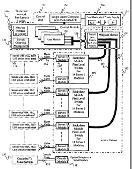
[0037] Figure 1 is a block diagram illustrating the various components of a
rack management
system according to one embodiment of the invention. In this implementation
the management
8
CA 02535374 2006-02-09
WO 2005/025374 PCT/US2004/013537
system includes two subsystems, a Vertical Column 102 and a Control Unit 104.
They are
communicatively coupled, via a cabling system for instance, to transfer
digital signals, analog
signals and power.
[0038] The Vertical Column 102 holds one or more switching Backplane Modules
(BM) 106.
Each Backplane Module 106 may house up to N (e.g., N is 14) Server Interface
Modules (SIM)
108. Alternately, where the rack unit location does not have a rack device,
the Server Interface
Modules 108 can be replaced with Server Cascade Modules 110 to extend the
control to slave
systems. A Midplane Module (MM) 118 is communicatively coupled to each
Backplane Module
106 to merge the multiple backplane buses 112.
[0039] Each Server Interface Module 108 is in close proximity to the rack
devices 114 (e.g.,
server or network equipment) assigned to its rack unit location. The Server
Interface Module
108 is communicatively coupled to its corresponding server 114 via a short
cable 116. In one
implementation of the invention a short cable 116 carries the set or subset of
interfaces including
video (e.g., VGA), PS/2 keyboard/mouse, universal serial bus (USB), and serial
RS232. The
Server Interface Module 108 has the necessary hardware and software to emulate
the physical
devices that the server 114 expects. That is, the Server Interface Module 108
merges/consolidates a variety of digital signals into a single high-speed bus
along with a separate
analog video line.
[0040] The Backplane Module 106 can be configured to selectively switch the
high-speed digital
"pipe" and video from each Server Interface Module to each of the N (e.g., N
is 4) user buses.
At the top end of the vertical column 102 there is a Midplane Module 118 which
performs a
second level switch selection of Server Interface Module signals in order to
consolidate the
Server Interface Module signals 112 from all of the Backplane Modules 106 and
connect to each
9
CA 02535374 2006-02-09
WO 2005/025374 PCT/US2004/013537
of the N user buses 130. In addition to this high-speed data and analog video
switched path to
each server there is also a serial bus that links all modules (e.g., SIMs,
BMs, MM) to provide
operational and maintenance (management) control by the Control Module (CM)
120 inside the
control unit 122.
[0041] The Control Unit 122 houses a Control Module 120, Single Board Computer
(SBC) 124,
and Dual Redundant Power Supply (DRPS) 126. The Control Module 120 houses a
backplane
system that allows User Modules (UM) 128 to be plugged in. There are at least
three different
types of User Modules: Local User Interface Module (LIM), Remote User
Interface Module and
the User Cascade Interface Module (UCIM). The Control Module 120 has multiple
processors
that manage and control all the modules (e.g., SIM, BM, MM, UM) and provides
the network
interface for remote management. Through the Network Interface 140 the data
path to the
servers 114 and the management bus are extended beyond the confines of the
local system.
[0042] The Dual Redundant Power Supply 126 includes two identical power
sources 132 and
134, from the AC input all the way to the output DC voltage, which are
combined with proper
isolation for continued normal operation in the event of failure on one of the
power sources.
[0043] The Single Board Computer 124 may be a self contained module with
enough processing
power, and resources (e.g., RAM, mass storage, network controller, etc.) to
run an embedded
operating system (e.g., Microsoft Windows XPTM) with high-powered
applications. According
to one implementation of the invention, software operating in the Single Board
Computer 124
enables automated self configuration and provisioning of the managed servers
114. The Single
Board Computer 124 executes applications that continuously gather data from
the servers 114,
receiving control events from the outside world and affecting changes of state
and configurations
CA 02535374 2006-02-09
WO 2005/025374 PCT/US2004/013537
within. The Single Board Computer 124 performs the above tasks, which are
usually
subordinated to the decision making process and implementation of an IT
specialist.
[0044] A Server Cascade Module 110 can replace one of the Server Interface
Modules 108, with
the purpose of controlling other slave systems 150. The slave systems may be
configured with
User Cascade Interface Modules to allow the control by the master system 122.
The connection
between the master system 122 and a slave system is via a one or more cables
152. In addition
to the server resources of the master system, once the slave system is coupled
to the master
system all the server resources from the slave system are also available to
the master system. In
one implementation, a master system may have a cascade module 110 coupled to a
User Cascade
Interface Module in a Control Unit of a slave system to permit control and/or
monitoring of the
slave system by the master system.
[0045] Figures 2 and 3 illustrate a Vertical Column mounted in a Rack Cabinet
according to one
embodiment of the invention. In one implementation of the invention, the rack
cabinet 202
includes a rear portion 204 with rails or brackets 206 in which a Vertical
Column 208 can be
secured. The Vertical Column 208 can be placed at various positions along the
rails 206. The
rack cabinet 202 also defines a space 210 in which one or more devices, such
as servers, network
equipment and/or other devices, may be mounted.
[0046] According to one embodiment of the invention, in order to support the
Vertical Column
208, the rack cabinet 202 includes two or more mounting brackets 206, that may
span a standard
19" rack cabinet. Each bracket 206 may be symmetrical and lU in height. In one
implementation of the invention, one bracket 206a is mounted behind the first
rack slot (e.g., unit
number 1) and another bracket 206b is mounted behind the last rack slot (e.g.,
unit number 42).
The brackets 206 are coupled to the mounting supports of the rack cabinet 202
and the Vertical
11
CA 02535374 2006-02-09
WO 2005/025374 PCT/US2004/013537
Column 208 is set into the keyhole 216 that provides the optimal position
within the rack cabinet
202 to couple the rack devices (e.g. servers, network equipment, storage
devices, etc.). There
may be a plurality of keyhole mount points 216 along the length of the
brackets 206.
[0047] According to one implementation of the invention, the Vertical Column
208 is a 42U
chassis that has a cross section of approximately 3.3 inches by 3.75 inches.
Each U in the
Vertical Column 208 contains a slot that can be filled with either a Server
Interface Module 108
for providing device access, a Cascade Module 152 or a blank cover. One or
more Backplane
Modules 106 may be located in the Vertical Column 208 to receive the Server
Interface Modules
212 (Figure 1, 108). The Backplane Modules 106 are electrically coupled to the
Midplane
Module 214 (Figure 1, 118; Figure 4, 404) by cables and/or buses inside the
Vertical Column
208.
[0048] The Vertical Column 208 may be configurable to provide different
numbers of U slots.
For example, the Vertical Column 208 could be reduced to 28U or 14U or any sub
42U
combination height. Consequently, the number of Backplane Modules within the
Vertical
Column 208 may also be changed as necessary.
[0049] Figure 4 illustrates a Vertical Column 208 with Server Interface
Modules 212 installed
therein according to one embodiment of the invention. The Vertical Column 208
houses
modular Server Interface Modules 212 along each lU section. The Server
Interface Modules
212 are coupled to connectors on one or more Backplane Modules 402 that are
arranged along
the rear of the Vertical Column 208. Such architecture helps reduce the length
of the interface
cables communicatively coupling the servers or other devices mounted in the
rack cabinet 202
and their corresponding Server Interface Modules 212. As previously discussed,
the overall
Vertical Column 208 location may also be adjustable along the support rails
206 to further
12
CA 02535374 2006-02-09
WO 2005/025374 PCT/US2004/013537
minimize the distance between the Vertical Column 208 and the servers or
devices within the
rack cabinet 202.
[0050] The Server Interface Modules 212 may be field and user installable to
allow for growth
and flexibility. For example, a user may add Server Interface Modules 212 to
the Vertical
Column 208 as servers and/or network equipment is added to a rack cabinet 202.
Additionally,
the Vertical Column 208 may also be used for adding mechanism to house
additional cables for
the rack cabinet 202, such as network wiring and/or other types of cables.
[0051] Figure 5 is a Control Unit 502 (illustrated as 122 in Fig. 1) according
to one embodiment
of the invention. The Control Unit 502 includes a Dual Redundant Power Supply
504 to provide
failsafe operation and one or more Single Board Computers 506 to implement the
enhanced
system features. Additionally, the Control Unit 502 may also include one or
more Control
Modules 510 and one or more User Modules 508 to manage the communication
interface with
servers and other devices in the rack cabinet 202. A plurality of User Modules
510 may serve to
provide local, remote and/or cascaded access to Server Interface Modules
(Figure 1, 108)
through the Control Unit 502. The User Modules and Control Modules 508 may be
separate
components that can be installed in the field to allow for growth flexibility.
[0052] Figure 6 illustrates how the Vertical Column 208 is coupled to a
Control Unit 502
according to one embodiment of the invention. The top of the Vertical Column
208 provides a
power connection and signal connection to the Control Unit 502. One or more
power and/or
communication cables 602 are coupled from the Control Unit 502 to a Midplane
Module 404
attached to the Vertical Column 208.
[0053] In one implementation of the invention, the control unit 502 may be
installed inside of the
rack cabinet 202, above the Vertical Column 208, occupying a lU space. Since
it is in an area
13
CA 02535374 2006-02-09
WO 2005/025374 PCT/US2004/013537
that is above and out the server and network equipment U space, it is optimal
to bring out all
external interfaces there for clutter free cabling.
[0054] Figure 7 is a block diagram illustrating the components of a Server
Interface Module 700
(illustrated as 108 in Fig. 1) according to one embodiment of the invention.
The Server Interface
Module 700 (also illustrated in Fig. 4 as 212) is a small electronic board or
card that can be
plugged into an interface in the Vertical Column 208. A plurality of Server
Interface Modules
700 may be distributed along the Vertical Column 208 (as illustrated in Figure
4).
[0055] One purpose of the Server Interface Module 700 is to reduce the number
of cables that
run along the back of a rack cabinet 202. The Server Interface Module 700
reduces the number
of cables that would otherwise run along the back of a rack cabinet 202 by
concentrating a
plurality cables into a single, multiple use cable. The Server Interface
Module 700 has an
interface 701 that plugs into a bus running along the backplane of the
Vertical Column 208. The
backplane bus carnes a plurality of different signal, such as Board ID, TTL
signals, Universal
Serial Bus (USB), and RGB video and synchronization, to and from the Server
Interface Module
700. These signals may be concentrated into a single interface to couple them
to a device (e.g.,
server, network equipment, storage equipment, etc.) in a rack cabinet.
[0056] A hybrid cable may be used to bundle all of the signals into a single
cable interface at the
Server Interface Module 700 end while providing a plurality of standard
interfaces at the server
or network equipment end. Figure 8 illustrates one embodiment of a hybrid
cable 800 that may
be used to couple a device, e.g., server or network equipment, to a Server
Interface Module
according to one implementation of the invention. This hybrid cable 800, along
with the Vertical
Column 208, reduces the number of individual cables that would otherwise need
to run to each
server in a rack unit.
14
CA 02535374 2006-02-09
WO 2005/025374 PCT/US2004/013537
[0057] According to one implementation of the invention, the hybrid cable 800
includes a
connector 802 at a first end to couple to a Server Interface Module. At the
opposite end 803, the
hybrid cable 800 splits into multiple cable interfaces. For example, the
second end of the hybrid
cable 800 may be split into a universal serial bus (USB) interface 804, a
keyboard connector 806,
a video connector 808, a mouse connector 810, and a serial port connector 812.
[0058] According to one implementation of the invention, the connector 802 is
a twenty-five
(25) pin connector in which pins are allocated such that all connectors at the
second end 803 can
be adequately supported. For example, the following table illustrates one
scheme for combining
various connectors into a hybrid twenty-five pin cable connector.
Twenty-five pin connector Corresponding Signal
18 RS232- Rx Data
19 RS232 - Tx Data
20 RS232 - Signal Ground
25 USB - Power
23 USB - Data +
24 USB - Data -
22 USB - Ground
7 Keyboard - Data
6 Keyboard - Signal Ground
9 Keyboard - Power (+SV)
8 Keyboard - Clock
12 Mouse - Data
6 Mouse - Signal Ground
13 Mouse - Power (+SV)
11 Mouse - Clock
1 Video - Red
2 Video - Green
3 Video - Blue
14 Video - Red Signal Return
15 Video - Green Signal Return
16 Video - Blue Signal Return
17 Video - Synchronization Ground
21 Video - DDC Clock
Video - DDC Data
4 Video - Horizontal Synchronization
5 Video - Vertical Synchronization
CA 02535374 2006-02-09
WO 2005/025374 PCT/US2004/013537
[0059] In this manner, all twenty-five (25) pins of the connector 802 are used
to electrically
couple to connectors 804, 806, 808, 810, and 812.
[0060] Referring again for Figure 7, the Server Interface Module 700 may
include a plurality of
components to process and/or manage the signals across the Server Interface
Module 700. A
microcontroller 702 receives a Board ID signal 703 and determines if
particular signals are
addressed to it. If so, a management bus 704 carries TTL serial signals 705 to
and from the
microcontroller 702. This bus 704 may be used to carry control signals to
and/or from a remote
system. The keyboard and/or mouse ports 706 and 708 of a server coupled to the
Server
Interface Module 700 are handled by peripheral processor 710 so that it can be
transferred to
processor 712 and then may be used to carry them to a remote system.
Additionally, one or more
peripheral processors 710 and 712 may process and transfer signals between the
backplane of the
vertical column and the server coupled to the Server Interface Module 700. For
instance, the
peripheral processors 710 and 712 may receive and transmit USB signals to and
from the
backplane, and convert it to one or more signals to the server ports, such as
RS232 port 714
signals or another USB port 716 signal. Other signals, such as the video
signal from the server's
video port 718, may pass through the Server Interface Module to the Backplane
701,
undisturbed. Microcontroller 702 has access to all programmable devices (I2C
EEPROM, PS2
processors) in the Server Interface Module, it can also communicate with the
rest of the
processors in the Server Interface Module board 700 (USB processor, PS2
processors). These
are important features that allow the self building and configuring of the
Server Interface
Module 700 during manufacturing.
[0061] The Server Interface Module 700 may be hot-swappable to permit
expanding the number
of modules in a Vertical Column without the need to shut off all devices in a
rack cabinet
16
CA 02535374 2006-02-09
WO 2005/025374 PCT/US2004/013537
connected to the Vertical Column. Such hot-swappable feature is made possible
by detect-and-
enable protection circuitry throughout the modules of the rack system
monitoring software that
identifies when new devices have been connected or come online and enabling
them through the
protection circuitry.
[0062] Figure 9 is a block diagram illustrating the components of a Server
Cascade Interface
Module 900 (illustrated as 110 in Fig. 1) according to one embodiment of the
invention. The
Server Cascade Interface Module 900 is a small electronic board or card that
can be plugged into
an interface in the Vertical Column 208. A plurality of Server Cascade
Interface Modules 900
may be distributed along the Vertical Column 208 (as illustrated in Figure 4).
[0063] One purpose of the Server Cascade Interface Module 900 is to extend the
control and
access of a first system to other slave systems. The Server Cascade Interface
Module 900 has an
interface 901 that plugs into a bus running along the backplane of the
Vertical Column 208. The
backplane bus carries a plurality of different signal, such as Board ID 903,
TTL signals 905,
Universal Serial Bus (USB), and RGB video and synchronization, to and from the
Server
Cascade Interface Module 900. These signals may be concentrated into a single
interface 916 to
couple them to a User Cascade Interface Module (Figure 1 S, 1500) that resides
in a slave system.
[0064] A special or standard off the-shelf cable may be used to bundle all of
the signals into a
single or dual cable interfaces) that interconnects the Server Cascade
Interface Module 900 to
the slave's User Cascade Interface Module (Figure 15, 1500). The design of the
Video driver
918 and the Data Serializer Driver/Receiver 914 in conjunction with the
Connector Interface 916
in the Server Cascade Interface Module 900, reduces the number of individual
cables that would
otherwise need to run between cascaded rack units.
17
CA 02535374 2006-02-09
WO 2005/025374 PCT/US2004/013537
[0065] The Server Cascade Interface Module 900 may include a plurality of
components to
process and/or manage the signals across the Server Cascade Interface Module
900. A
microcontroller 902 receives a Board ID signal 903 and determines if
particular signals are
addressed to it. If so, a management bus 904 carries TTL serial signals 905 to
and from the
microcontroller 902. This bus 904 may be used to carry control signals to
and/or from a remote
control system. Additionally, one or more peripheral processors 910 and 912
may process and
transfer signals between the backplane of the Vertical Column and the slaved
rack unit coupled
to the Server Cascade Interface Module 900. For instance, the peripheral
processors 910 and 912
may receive and transmit USB signals to and from the backplane, and convert it
to one or more
signals to the Data Serializer Driver/Receiver 914 and to the Cascaded
Connector 916. Other
signals, such as the video signal from the Cascaded Connector 916, may pass
through the Video
Receiver/Driver 918 to the Backplane 901, undisturbed. Microcontroller 902 has
access to all
programmable devices (e.g., I2C EEPROM, Data Serializer program) in the Server
Cascade
Interface Module 900, it can also communicate with the rest of the processors
in the board: USB
processor 910, Data Serializer 914. These are very critical features that
allow the self building
and configuration of the board during manufacturing.
[0066] The Server Cascade Interface Module 900 may be hot-swappable to permit
expanding the
number of modules in a Vertical Column without the need to shut off all
devices in a rack
cabinet connected to the Vertical Column. Such hot-swappable feature is made
possible by
detect-and-enable protection circuitry throughout the modules of the rack
system in conjunction
with the monitoring software that identifies when new devices have been
connected or come
online and enabling them through the protection circuitry.
18
CA 02535374 2006-02-09
WO 2005/025374 PCT/US2004/013537
[0067] Figure 10 is a block diagram illustrating a Backplane Module 1000
according to one
implementation of the invention. The Backplane Module 1000 may be located
within the
Vertical Column and provide one or more interfaces in which to couple one or
more Server
Interface Modules (Figure 1, 108; Figure 7, 700). The Backplane Module 1000 is
a switch that
allows Server Interface Module cards (Figure 1, 108; Figure 7, 700) to plug to
the connectors
1002 for power and routing of signals to the proper destination user module.
In one
implementation of the invention, each Backplane Module 1000 is segmented to
handle up to
fourteen (14) Server Interface Module cards (Figure 1, 108; Figure 7, 700) for
flexibility in
arranging different product configurations.
[0068] A Backplane Module 1000 may include a micro-controller 1004 that
controls a plurality
of switches 1006, 1008, and 1010 to select one of a plurality of Server
Interface Modules (Figure
l, 108; Figure 7, 700) that may be coupled to the Backplane Module 1000 via
connectors 1002.
That is, the sync selector 1006 selects one of a plurality of synchronization
signals from the
Server Interface Modules (Figure 1, 108; Figure 7, 700) coupled to connectors
1002, the video
switch 1008 selects one of the video signals coming from the Server Interface
Modules, and the
USB switch 1010 selects one of the USB signals from the Server Interface
Modules. Signals
from a management bus interface 1012 are transferred to and from the micro-
controller 1004 and
directly to a second management bus interface 1014 to the Server Interface
Modules. The
Backplane Module 1000 may also include a Server Interface Module detect-and-
enable unit 1016
to detect when a Server Interface Module (Figure 1, 108; Figure 7, 700) is
coupled to the
connectors 1002 and enable operation of that Server Interface Module. A module-
reset unit
1018 permits the Backplane Module 1000 to reset a Server Interface Module when
instructed to
do so.
19
CA 02535374 2006-02-09
WO 2005/025374 PCT/US2004/013537
[0069] Figure 11 is a block diagram illustrating a Midplane Module 1100
(illustrated as 118 in
Fig. 1) according to one embodiment of the invention. The Midplane Module 1100
is a switch
that concentrates the signals from the different Backplane Modules 106 (Fig.
1) into a single bus
to the Control Module 120 (Fig. 1). The Midplane Module 1100 has a similar
layout as the
Backplane Module 1000. A micro-controller 1104 controls signals to and from
the Midplane
Module 1100. The micro-controller 1104 receives control signals over the
management bus
1112 and configures the selector 1106 and switches 1108 and 1110 accordingly
to enable signal
transmissions to and from a particular Backplane Connector 1120. The Midplane
Module 1100
may also include a backplane detect-and-enable unit 1116 to detect when a
Backplane Module
(Figure 10, 1000) is present at a Backplane Connector 1120 and enable
operation of that
Backplane Module. A module-reset unit 1118 permits the Midplane Module 1100 to
reset a
Backplane Module (Figure 10, 1000) when instructed to do so.
[0070] The Midplane Module 1100 helps ease the cabling requirements between
the Vertical
Column 102 and the Control Module 120 (Fig. 1). That is, rather than having
multiple cables
running from each Backplane Module (Figure 1, 106) to the Control Module 120,
a single cable
may be used between the Control Module cable connector 1122 and the Control
Module
connector 130 (Fig. 1).
[0071] Figure 12 is a block diagram illustrating a Control Module 1200
(illustrated as 120 in Fig.
1) according to one embodiment of the invention. The Control Module 1200
provides the main
switching control unit and user interface system. According to one
implementation of the
invention, the Control Module 1200 is part of the Control Unit (Figure 1,
122), which is lU in
height. The Control Module 1200 has the board detect feature and separate user
module busses
1202, because of this and of software support, the User Modules (Figure 1,
128) may be hot-
CA 02535374 2006-02-09
WO 2005/025374 PCT/US2004/013537
swappable to permit expanding the number of User Modules (Figure 1, 128) in a
Control Unit
(Figure 1, 120; Figure 5, 502) without the need to shut off the Control Unit
(Figure 1, 120;
Figure S, 502), the Vertical Column and/or the devices in a rack cabinet
connected to the Vertical
Column.
[0072] One implementation of the Control Module 1200 includes a plurality of
user card slots or
connectors 1202 which permit multiple users to simultaneously access servers
via the Control
Module 1200. A mix of Local Interface Modules (LIM), Remote Interface Modules
(RIM), and
User Cascade Interface Module (UCIM) can be plugged into the user card
connectors 1202 and
provide access to the Midplane Module 118 (Figure 1) via connector 1204. The
Control
Module's Control Processors 1218 manages the Midplane via interface 1206 and
the User
Modules via serial controller 1208. The network processor 1212 provides the
network access for
the system, it bridges between the external network via 1220 to the User
Modules via 1210 and
via 1214 to Control Processor 1218. The Control Processor 1218 also extends
the management
functions to external rack infrastructure such as: fan, intelligent power
strip for servers, UPS, etc,
all via the serial interfaces 1214. Both the network processor 1212 and the
Control Processor
1218 share a data flash storage 1216 to hold all sorts of non-volatile
information.
[0073] The Control Module 1200 may also include a plurality of connectors
and/or interfaces,
such as RJ45 connection, a 10/100/1000 Mb link to a network, a 10/100 Mb link
for to the
system management bus.
[0074] Figure 13 is a block diagram illustrating a Local Interface Module
(LIM) 1300 according
to one embodiment of the invention. The Local Interface Module 1300 is a type
of user card that
can be plugged into the User Module Connectors 1202 of the Control Module
1200. The Local
Interface Module 1300 delivers local access of the servers coupled to the
Vertical Column.
21
CA 02535374 2006-02-09
WO 2005/025374 PCT/US2004/013537
(0075] According to one implementation of the invention, the Local Interface
Module (LIM)
1300 may include a microprocessor subsystem 1302 having a processor and
memory. The Local
Interface Module 1300 may include one or more interface ports or connectors
for a keyboard
interface 1304, mouse interface 1306, a video interface 1308, and one or more
USB interfaces
1310 and 1312. The keyboard interface 1304, mouse interface 1306 permit a user
to provide
input to the Local Interface Module while the USB subsystem 1314 and 1316 and
interfaces
1310 and 1312 enable USB-compliant devices to be connected to the Local
Interface Module
1300. The video subsystem 1318 and 1320 and interface 1308 permits connection
of an output
device, such as a display unit, where a user may view the applications being
executed on the
Local Interface Module 1300 as well as access information and/or applications
from one or more
user-selected servers. For example, the Local Interface Module 1300 may
provide an on-screen
display that allows a user or operator to navigate the attached systems
(Control Unit, Vertical
Column, Midplane Module, Backplane Modules, servers, etc).
[0076] Used in conjunction with system management software, the Local
Interface Module 1300
provides keyboard, video, and mouse access to the Vertical Column and all of
the components
electrically coupled thereto.
(0077] Additionally, the Local Interface Module 1300 may provide a terminal
emulator allowing
users to manage and configure serial devices such as routers or managed
switches. The Local
Interface Module 1300 may also support optional USB device sharing. This can
be used for
peripheral device consolidation and/or biometric security devices.
[0078] According to one implementation of the invention, USB device sharing
provides the
ability to attach a single or several USB peripheral devices to the local
management card of the
server rack. The servers in the server rack may then have access to the
peripheral devices. This
22
CA 02535374 2006-02-09
WO 2005/025374 PCT/US2004/013537
permits using a single device, e.g., a CD-ROM, per server rack as opposed to
the current trend of
integrating a separate device, e.g., a CD-ROM, into each server or computer.
In another
implementation, card readers and/or biometric readers may be used to provide
server
authentication. Instead of having a single authentication device per server,
or a separate USB
switch in each server dedicated to support an external authentication device,
the server rack
management system can share that authentication or peripheral device (e.g.,
card reader,
biometric reader, etc.) with each connected server. These USB devices would be
connected to
the Local Interface Module 1300 while the switching through the column would
provide a
connection to any of the servers connected to the Server Interface Module 1300
in the column.
[0079] Figure 14 is a block diagram illustrating Remote Interface Module (RIM)
1400 according
to one embodiment of the invention. A Remote Interface Module 1400 allows a
user or operator
to navigate the attached systems (e.g., Control Unit, Vertical Column,
Midplane Module,
Backplane Module, servers, etc.) over an IP network. The Remote Interface
Module 1400 is a
type of user card that can be plugged into the User Interface Module
connectors 1202 of the
Control Module 1200. The Remote Interface Module 1400 includes a micro-
controller 1402, in
conjunction with a USB subsystem 1404 and video subsystem 1406 and 1408,
translates the
signals from the Control Module interface 1202 into IP packets and transfers
the data over the
Ethernet interface 1410 to the network port 1220 of the control module 120.
[0080] In one implementation of the invention, up to four Remote Interface
Module 1400 cards
may be installed in a control module to provide a 4xN switch access, where N
can typically be
forty-two (42). The Remote Interface Module 1400 may digitize video signals
and packetize it
along with other digital data (e.g., USB and/or management data) into IP
packets to be sent to
remote locations via the Internet.
23
CA 02535374 2006-02-09
WO 2005/025374 PCT/US2004/013537
[0081] Figure 15 is a block diagram illustrating User Cascade Interface Module
(UCIM) 1500
according to one embodiment of the invention. A UCIM 1500 allows the user or
operator in an
external master rack unit to navigate the attached slave systems (e.g.,
Control Unit, Vertical
Column, Midplane Module, Backplane Module, servers, etc.) over the cascade
cable
interconnection (Figure 16, 1602). The User Cascade Interface Module 1500 is a
type of user
card that can be plugged into the User Module connectors 1202 of the Control
Module 1200.
The User Cascade Interface Module 1500 includes a micro-controller 1502, in
conjunction with a
USB processor 1504 and video receiver/driver 1506, translates the signals from
the control
module interface 1202 into Data Serializer driver 1508 and the Cascade
Connector 1510 and
transfers the data over the cascade cable bundle (Figure 16, 1602). In one
implementation of the
invention, a Cascade Interface Module (Figure 1 S, 1500) is configured to send
reconditioned
analog video and digital data to an external master rack unit, in a point-to-
point communication
scheme, to enable a user or operator in the external master rack unit to
navigate the attached
slave systems.
[0082] In one implementation of the invention, up to four User Cascade
Interface Module cards
(Figure 15, 1500) may be installed in a slave Control Module (Figure l, 120)
to provide a 4xN
switch access to the master rack unit, where N can typically be forty-two
(42). Figure 16
illustrates one embodiment of a connection arrangement between a slave system
cascaded to a
master system. The User Cascade Interface Module 1600 in Control Unit 1601 is
slaved to a
Server Cascade Module (Figure 16, 1604) in the master Vertical Column 1606,
through a
cascade cable 1602. In this manner, the Control Unit 1608, located in a first
rack unit, may
control the equipment and/or servers coupled to Control Unit 1601 and the
slave Vertical
Column 1610 located in a second rack unit.
24
CA 02535374 2006-02-09
WO 2005/025374 PCT/US2004/013537
[0083] Figure 17 is a block diagram illustrating a Dual Redundant Power Supply
(DRPS) system
1400 (illustrated as 126 in Fig. 1) according to one embodiment of the
invention. The system is
fed with a dual AC input sources 1702 and 1704 into redundant power supplies
1706 and 1708.
This allows separate AC feeds 1702 and 1704 to enter the unit 126 providing
protection against
both a power distribution unit failure and a power supply module failure. In
the event of a power
supply failure, the Control Unit 122 notifies the user, allowing a scheduled
maintenance period
to be set. A power distribution module 1710 provides a DC power output from
the redundant
power supplies 1706 and 1708 feed the control module 120, the Single Board
Computer 124, the
Vertical Column 102 (Fig. 1), and other devices.
[0084] According to one embodiment of the invention, a user interface device
is provided that
enables an operator to access and manage devices communicatively coupled to
the Control Unit
122, including the Single Board Computer 124, Control Module 120, Midplane
Module 118,
Vertical Column 102, Backplane Modules 106, Server Interface Modules 108,
power supplies
126, and servers 114. In one implementation, the user interface device may be
lU-high
enclosure including a flat panel display unit, a keyboard and a touchpad
system that mounts in a
standard rack mount cabinet. This system allows for direct connectivity to a
Local Interface
Module in order to access and manage a system locally. Figures 18-20
illustrate a user interface
device that enables an operator to access and manage devices communicatively
coupled to the
Control Unit 122 according to one embodiment of the invention. Figure 18
illustrates the top
and side views of the user interface device 1800. The dimensions of the user
interface device
1800 are such that, in one position, it fits within a single U space of a rack
unit. The user
interface device 1800 may be coupled to rails 1802 that permit the user
interface device 1800 to
slide in and out of the rack unit. Figure 19 illustrates a perspective view of
the user interface
CA 02535374 2006-02-09
WO 2005/025374 PCT/US2004/013537
device 1800 in a closed position. Figure 20 illustrates a second perspective
view of the user
interface device 1800 in an open position. The user interface device 1800 may
include a display
unit 2002, a keyboard 2004, and a pointing device 2006 to permit a user to
operate software
programs that provide control over other rack mounted devices.
[0085] According to various embodiments of the invention, one or more user
interfaces device
1800 may be mounted in one or more rack cabinets to permit users to access
equipment and/or
servers in a plurality of networked rack cabinets. For instance, a single user
interface 1800 may
enable first user to access a first set of servers in one or more rack
cabinets while enabling a
second user to access a second set of server in one or more rack cabinets.
[0086] In yet another implementation of the invention, a user may remotely
access, control,
and/or monitor equipment and/or servers in one or more rack cabinets. For
example, using
network interface 140, a user may access a control unit 122 from which local
and networked
servers in one or more rack cabinets may be controlled, monitored, and/or
accessed.
[0087] Another feature of the invention provides an application that may be
executed on a
remote terminal to access on or more systems in a rack unit (e.g. Single Board
Computer,
Control Module, Midplane Module, Backplane Module, Server Interface Module, or
servers)
over an IP based network. One feature of the application allows a user to log
onto the system
and authenticate across the network's Active Directory (AD) to determine to
what devices the
user may have management access and/or read-only access. The application may
provide a
graphical user interface of the management system and allow for key sequences
to be sent to the
remotely connected systems.
[0088] Yet another feature of the invention provides centralization of
security management.
Typically, each portion of rack management (e.g., server, power and
environment management)
26
CA 02535374 2006-02-09
WO 2005/025374 PCT/US2004/013537
has its own passwords and security settings. One embodiment of the present
invention provides
centralized security back to the network's Active Directory (AD). The AD
determines what
access level a user has to manage particular devices within a data center, a
rack or even a
component within the device. This centralized security system eliminates the
need for separate
security schemes for each portion of the system (e.g., server, power and
environment
management). Such centralized security leverages the use of a data center's
existing security
control server, sometimes also called security domain controller. In other
embodiment of the
invention when the centralized security server is not available, the Control
Module hosts its own
security authentication for access to the server management.
[0089] Yet another feature of the invention provides for other components that
extend the
capabilities of the rack management system.
[0090] For instance, one embodiment of the invention may include a top-level
application that
manages multiple rack units. Such system may operate on an embedded Microsoft
Windows TM
operating system. The top-level application may gather and provide performance
metrics and
scripts to be managed and distributed to the devices throughout the attached
rack.
[0091] Another aspect of the invention provides a distributed patch panel in
which a 40U bracket
attaches to the vertical column and terminates up to three RJ45 jacks/ports
per rack U allowing
for the integration of distributed data patch cables. The top of the vertical
column may terminate
at a switch or other network device located in the top of the rack.
[0092] According to another embodiment of the invention, a vertical cable
management tray can
be added to the system in place of the distributed patch panel. This enables
the organized
vertical routing of any additional cables not directly handled by the
invention.
27
CA 02535374 2006-02-09
WO 2005/025374 PCT/US2004/013537
[0093] Another embodiment of the invention provides high-density power
distribution units
(PDUs) in order to distribute the power evenly throughout the rack unit and
minimize power
cabling. Each Power Distribution Unit attaches to the Control Module through
one or more
serial ports. The Control Module can then control the Power Distribution
and/or read its
metering statistics. As an option the Power Distribution Unit will have the
ability to recycle
power on a per port basis via the RS-232 ports of the Control Unit.
[0094] Another aspect of the invention provides for power metering of total
current draw. This
data in combination with the server's utilization statistics may be used to
determine where power
costs can be reduced in a data center.
[0095] Another feature of the scalable rack cabinet is that the Vertical
Column can be scaled to
14U columns, 28U columns, or more as needed. This is accomplished by providing
modules
(e.g., Backplane Modules, Server Interface Modules, etc.) that can be added to
the Vertical
Column as necessary. The system management software may be configured to
permit the use of
a different number of modules along the system.
[0096] The management software may also be configured to gather data sets,
allowing for an
overall map of a data center to be created. This allows for analysis of open
rack areas and
finding servers through the use of various metrics. The data may be mapped
into a system
mapping software package in order to provide elevation charts of the
installation.
[0097] The rack architecture provides the hardware baseline to allow servers
to become generic
processing units. Servers are typically deployed with specific tasks, such as
web serving or
database functions. If access to a server is low, the server continues to run
in a static state
consuming power and generating heat. This methodology has led to processor
utilization figures
that are in the single digits for most all data centers. The increased need
for computing has led to
28
CA 02535374 2006-02-09
WO 2005/025374 PCT/US2004/013537
increased density, which in turn has presented the issue of providing
sufficient cooling and
power to the servers in a data center. The idea of using fewer computers more
wisely has not
been practical since there was not an efficient way of monitoring processing
loads and
controlling a plurality of servers.
[0098] According to one embodiment of the present invention, the centralized
control of servers
within a server rack combined with a robust software platform permits managing
a pool of
storage devices, networking devices and servers. This centralized management
tool allows an
operator to run a data center based on a pre-determined best practices
methodology or tweak the
utilization thresholds to meet the requirements of a more customized
installation. For example,
if a mail server was operating at five percent (5%) capacity between the hours
of nine (9) PM to
six (6) AM the management system may direct that activity to another server
and sequentially
power down the underutilized or stagnant server. When capacity is required,
the system may be
brought up and made available to share the load. This eliminates wasted energy
in both cooling
and powering of the equipment. Additionally, such intelligent system
management eliminates
the need for expensive load balancing systems since the feedback loop has been
migrated to the
device manager as opposed to the network exclusively. The "feedback loop"
refers to the
intelligent sampling and the application of the appropriate corrective action.
If this feedback is
handled on the network exclusively, decisions are made based solely on network
traffic and
network transaction data. Such network-based decisions ignore important
factors such as the
operating environment, power consumption, and processor utilization.
[0099] With the ability to collect data such as processor speed, memory
capacity, port capacity
and hard drive capacity etc. the system can build a record of the complete
rack environment
based on the data gathered and applying rules programmed into the Single Board
Computer 124.
29
CA 02535374 2006-02-09
WO 2005/025374 PCT/US2004/013537
This allows a server rack system to provision itself of the equipment therein
(e.g., servers,
storage, etc.) based on simple commands provided by the operator and build a
stable and secure
software environment with minimal human intervention.
[00100] In one implementation of the invention, by maintaining configuration
and
provisioning information about resources in a server rack and/or data center,
an operator can
actively control the migration of programs, data or responsibilities of the
equipment, thus making
hardware upgrades significantly simpler.
[00101] According to one implementation of the invention, a metering feature
of the
management system provides constant data gathering and analysis in order to
predict failures of
components or systems. Upon an alert, a human operator can be notified and/or
measures can
be automatically taken based on the rules programmed into the Single Board
Computer 124.
This data can be used to judge the relative useful life remaining on
components or provide a
financial analysis on the benefits of upgrading to more current technology. In
essence, metering
analysis takes the guesswork out of information technology infrastructure
capacity planning.
[00102] Since the management system is capable of gathering physical location
and
contents/configuration of each attached device, it can be instrumental in
asset management. A
top level program can gather desired elements of data from each server rack
within a data center
or company and provide a detailed inventory on assets and physical locations.
This information
is also useful in planning optimal deployment areas within a data center.
[00103] According to one implementation of the invention, the management
system may
also be employed in network load generation. Typically, if a server has become
saturated the
network will continue to broadcast and route packets to a particular resource
(e.g., server).
However, according to one implementation of the invention, a resource (e.g.,
server) reports back
CA 02535374 2006-02-09
WO 2005/025374 PCT/US2004/013537
to the centralized management system that it has reached a threshold level of
utilization, e.g.,
85% capacity. The management system may then send a command to a router to
scale back the
broadcasting or shift the resource to a different device. This helps reduce
networking traffic and
maximizes total system performance. The centralized management architecture
permits using
available hardware for load shifting by providing a communication and
reporting loop to monitor
loads and usage metrics.
[00104] Another feature of the invention provides for centralizing the
management of the
devices within a rack cabinet (e.g., server, network equipment, power and
environmental
equipment, etc.). According to one implementation of the invention, each rack
cabinet is
associated with a particular identifier. For instance, the control module in a
rack cabinet may be
associated with a unique Internet Protocol (IP) address within a data center.
This IP address
permits identifying the location of a device within a data center.
Additionally, an operator can
remotely access a device over a network by using the IP address of the rack
cabinet in which the
device resides and accessing the device list for that rack cabinet. This IP
address provides access
to both IP based third party products as well as serial based third party
products. In essence the
IP address is a gateway to all management devices within the rack cabinet.
[00105] While certain exemplary embodiments have been described and shown in
the
accompanying drawings, it is to be understood that such embodiments are merely
illustrative of
and not restrictive on the broad invention, and that this invention not be
limited to the specific
constructions and arrangements shown and described, since ~ various other
modifications are
possible. Those skilled, in the art will appreciate that various adaptations
and modifications of
the just described preferred embodiment can be configured without departing
from the scope and
spirit of the invention. Additionally, it is possible to implement embodiments
of the invention or
31
CA 02535374 2006-02-09
WO 2005/025374 PCT/US2004/013537
some of their features in hardware, programmable devices, firmware, software
or a combination
thereof. The invention or parts of the invention may also be embodied in a
processor-readable
storage medium or machine-readable medium such as a magnetic (e.g., hard
drive, floppy drive),
optical (e.g., compact disk, digital versatile disk, etc), or semiconductor
storage medium (volatile
and non-volatile). Therefore, it is to be understood that, within the scope of
the appended claims,
the invention may be practiced other than as specifically described herein.
32