Language selection

Search

Patent 2541673 Summary

Third-party information liability

Some of the information on this Web page has been provided by external sources. The Government of Canada is not responsible for the accuracy, reliability or currency of the information supplied by external sources. Users wishing to rely upon this information should consult directly with the source of the information. Content provided by external sources is not subject to official languages, privacy and accessibility requirements.

Claims and Abstract availability

Any discrepancies in the text and image of the Claims and Abstract are due to differing posting times. Text of the Claims and Abstract are posted:

  • At the time the application is open to public inspection;
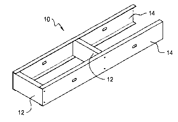
  • At the time of issue of the patent (grant).
(12) Patent Application: (11) CA 2541673
(54) English Title: FRAMING SYSTEM FOR BUILDINGS
(54) French Title: SYSTEME D'OSSATURE POUR BATIMENTS
Status: Deemed Abandoned and Beyond the Period of Reinstatement - Pending Response to Notice of Disregarded Communication
Bibliographic Data
(51) International Patent Classification (IPC):
  • E04C 2/38 (2006.01)
(72) Inventors :
  • MEEK, MICHAEL A. (United States of America)
  • PLUEARD, DAVID D. (United States of America)
(73) Owners :
  • ALLIED TUBE & CONDUIT CORPORATION
(71) Applicants :
  • ALLIED TUBE & CONDUIT CORPORATION (United States of America)
(74) Agent: SMART & BIGGAR LP
(74) Associate agent:
(45) Issued:
(86) PCT Filing Date: 2004-10-06
(87) Open to Public Inspection: 2005-04-21
Availability of licence: N/A
Dedicated to the Public: N/A
(25) Language of filing: English

Patent Cooperation Treaty (PCT): Yes
(86) PCT Filing Number: PCT/US2004/034162
(87) International Publication Number: WO 2005035891
(85) National Entry: 2006-04-05

(30) Application Priority Data:
Application No. Country/Territory Date
10/683,947 (United States of America) 2003-10-10

Abstracts

English Abstract


A framing system for buildings that includes a plurality of studs and track
mounted together to form a unique framing system. Each stud defines a
longitudinally extending body, opposing foldable end flaps, and opposing
flanges that extend outwardly from the body. Each of the opposing flanges also
includes a second flange that extends outwardly from the opposing flanges at
approximately an angle of ninety degrees. Mounted to the plurality of studs is
the plurality of track. Each of the plurality of track defines a
longitudinally extending track body and opposing track flanges extending
outwardly from the track body.


French Abstract

Système d'ossature pour bâtiments, qui comporte une pluralité d'entretoises et de rails montés ensemble pour former un système d'ossature unique en son genre. Chaque entretoise présente un corps à extension longitudinale, des pans terminaux opposés pliables et des brides opposées qui s'étendent vers l'extérieur à partir du corps. Chacune des brides opposées comporte également une seconde bride qui s'étend vers l'extérieur par rapport aux brides opposées, à un angle d'environ quatre-vingt-dix degrés. Une pluralité de rails est montée sur la pluralité d'entretoises. Chaque rail possède un corps à extension longitudinale et des brides de rail opposées qui s'étendent vers l'extérieur à partir dudit corps de rail.

Claims

Note: Claims are shown in the official language in which they were submitted.

What We Claim Is:
1. A framing system for storage buildings comprising:
a plurality of studs each stud defining a longitudinally extending body and
opposing first
flanges extending outwardly from the body at approximately an angle of ninety
degrees, each
stud further defining opposing second flanges extending outwardly from the
opposing first
flanges at approximately an angle of ninety degrees, each study also defining
opposing
foldable end flaps,
a plurality of track mounted to the plurality of studs, each track defining a
longitudinally
extending track body and opposing track flanges extending outwardly from the
track body at
an angle of approximately ninety degrees.
2. The framing system of Claim 1 wherein the plurality of track further
includes a
plurality of mounting holes for the mounting of the track to the stud.
3. The framing system of Claim 2 wherein the track is mounted to the foldable
end flaps
of the stud.
4. The framing system of Claim 3 wherein the plurality of track and the
plurality of
studs are made from carbon steel with a galvanized zinc coating.
5. A framing system for storage buildings comprising:
a plurality of studs, each stud defining a longitudinally extending body and
opposing first
flanges extending outwardly from the body at approximately an angle of ninety
degrees, each
stud further defining opposing second flanges extending outwardly from the
opposing first
flanges at approximately an angle of ninety degrees, each stud also defining
opposing foldable
end flaps,
a plurality of track mounted to the plurality of studs, each track defining a
longitudinally
extending track body and opposing track flanges extending outwardly from the
track body at
an angle of approximately ninety degrees, each track also includes a plurality
of mounting
holes for the mounting of the track to at least one of the plurality of studs.
6. The framing system of Claim 5 wherein the track is mounted to the foldable
end flaps
of the stud.

7. The framing system of Claim 6 wherein the plurality of track and the
plurality of
studs are made from carbon steel with a galvanized zinc coating.

Description

Note: Descriptions are shown in the official language in which they were submitted.


CA 02541673 2006-04-05
WO 2005/035891 PCT/US2004/034162
Title: FRAMING SYSTEM FOR BUILDINGS
[0001] Storage buildings, sheds, and other similar buildings are quite known
as providing a
sheltered structure for numerous items, such as automobiles, agricultural
equipment,
gardening equipment, and the like. These structures are typically in an
outdoor
environment and must withstand various, and sometimes extreme, weather
conditions. The underlying framing system of these known buildings is what
provides the durability to withstand the sometimes extreme environmental
conditions.
It has become apparent that improvements in the framing system results in
improvements in the durability and longevity of the building. Consequently,
there is
a continuing need for improvements in the underlying framing structure that
supports
the storage building, shed, or other similar building.
[0002] The present invention is directed at such an improvement over existing
framing
systems.
BRIEF SUMMARY OF THE INVENTION
[0003] The present invention is directed to a framing system for storage
buildings, sheds,
shelters, houses or other buildings that store, house, or contain various
items and
things. The framing system of the invention is directed to framing structures
that use
studs and track as the supporting structure. The invention is particularly
useful as the
underlying framing structure for the floor of a building. Under the present
invention,
each stud defines a longitudinally extending body and opposing flanges that
extend
outwardly from the body. Each flange also includes a second flange that
extends
outwardly from the opposing flanges at approximately an angle of ninety
degrees.
Each stud also defines opposing foldable end flaps. Mounted to the plurality
of studs
at the end flaps is the plurality of track. Each track defines a
longitudinally extending
track body and opposing track flanges extending outwardly from the track body.
As a
1

CA 02541673 2006-04-05
WO 2005/035891 PCT/US2004/034162
system, the studs and track of the invention create a stronger and more
durable
framing structure over known structures.
BRIEF DESCRIPTION OF THE DRAWINGS
[0004] Figure I shows an isometric view of the framing system of the present
invention.
[0005] Figure 2 shows an exploded isometric view of the invention of Figure 1.
[0006] Figure 3 shows an isometric view of the stud of the invention of Figure
1.
[0007] Other features and advantages of the invention will become apparent to
those skilled
in the art upon review of the following detailed description, claims and
drawings in
which like numerals are used to designate like features.
DETAILED DESCRIPTION OF THE INVENTION
[0008] The invention may be embodied in various forms. Referring to the
Figures wherein
like numerals are used to designate like features, there is depicted in Figure
I a
framing system 10 of the present invention. The framing system 10 includes a
plurality of studs 12 and a plurality of track 14 that are mounted together to
make a
portion of the underlying frame for a building, such as a storage building,
shed,
shelter, house or other similar buildings. The framing system 10 is
particularly useful
as the frame underlying the floor of a storage building or shed. The
individual studs
12 and track 14 are further depicted in Figure 2.
[0009] Referring to Figure 3, the stud 12 defines a longitudinally extending
body 16 having
opposing ends 18, 20 and opposing sides 22, 24. Extending outwardly from the
sides
22, 24 of the body 16 are opposing flanges 26. The flanges extend outwardly at
approximately an angle of 90 degrees from the body 16. Located at the ends 28
of the
flanges 26 are second opposing flanges 30 that extend outwardly at
approximately an
angle of 90 degrees from the flanges 26. As depicted, the flanges 30 extend
parallel
to the body 16 and toward the longitudinal center of the body 16. The body 16
and
2

CA 02541673 2006-04-05
WO 2005/035891 PCT/US2004/034162
flanges 26, 30 form a stud that has a C-shaped cross section. One of skill in
the art
will understand that other similar stud shapes and configurations are
possible.
[0010] Located at the ends 18, 20 of the stud 12 are a plurality of holes or
slots 29 positioned
linearly and extending transversely across the body 16 of the stud. Also
located at the
ends 18, 20 are foldable end flaps 31 that, as depicted, are foldable along
the plurality
of holes 29. The foldable flaps define a mounting surface on which the track
14 may
be attached and also serve as a stiffener for the study 12. As depicted, the
track 14
may be mounted to the stud 12 at various positions along the track 14.
[0011] Referring to Figure 2, the track 14 includes a longitudinally extending
body 32 with
opposing ends 34, 36 and opposing sides 38, 40. Extending outwardly from the
opposing ends 34, 36 are opposing flanges 42. The opposing flanges 42 extend
outwardly at an angle of approximately 90 degrees from the body 32. Mounting
holes 44 are positioned along the body 32 of the track to permit the mounting
of the
track 14 to the stud 12 and specifically to the end flaps 31 of the study 12.
As is
known in the art, fasteners or rivets or the like may be used to mount the
track 14 to
the stud 12. Again, one skilled in the art will understand that other shapes
and
configurations of the track are possible.
[0012] The stud 12 and track 14 are preferably made of flat rolled carbon
steel with a
galvanized zinc coating for added corrosion resistance. It should be
understood by
those skilled in the art that other suitable materials may be used with the
present
invention depending on the application and the environment in which the
framing
system is to be used.
[0013] While the invention has been described with respect to specific
examples including
presently preferred modes of carrying out the invention, those skilled in the
art will
appreciate that there are numerous variations and permutations of the above
described
3

CA 02541673 2006-04-05
WO 2005/035891 PCT/US2004/034162
systems and techniques that fall within the spirit and scope of the invention
as set
forth in the appended claims.

Representative Drawing
A single figure which represents the drawing illustrating the invention.
Administrative Status

2024-08-01:As part of the Next Generation Patents (NGP) transition, the Canadian Patents Database (CPD) now contains a more detailed Event History, which replicates the Event Log of our new back-office solution.

Please note that "Inactive:" events refers to events no longer in use in our new back-office solution.

For a clearer understanding of the status of the application/patent presented on this page, the site Disclaimer , as well as the definitions for Patent , Event History , Maintenance Fee  and Payment History  should be consulted.

Event History

Description Date
Time Limit for Reversal Expired 2008-10-06
Application Not Reinstated by Deadline 2008-10-06
Deemed Abandoned - Failure to Respond to Maintenance Fee Notice 2007-10-09
Letter Sent 2007-05-18
Inactive: Single transfer 2007-04-04
Inactive: Cover page published 2006-06-13
Inactive: Courtesy letter - Evidence 2006-06-13
Inactive: Notice - National entry - No RFE 2006-06-09
Application Received - PCT 2006-05-04
National Entry Requirements Determined Compliant 2006-04-05
Application Published (Open to Public Inspection) 2005-04-21

Abandonment History

Abandonment Date Reason Reinstatement Date
2007-10-09

Maintenance Fee

The last payment was received on 2006-09-27

Note : If the full payment has not been received on or before the date indicated, a further fee may be required which may be one of the following

  • the reinstatement fee;
  • the late payment fee; or
  • additional fee to reverse deemed expiry.

Please refer to the CIPO Patent Fees web page to see all current fee amounts.

Fee History

Fee Type Anniversary Year Due Date Paid Date
Basic national fee - standard 2006-04-05
MF (application, 2nd anniv.) - standard 02 2006-10-06 2006-09-27
Registration of a document 2007-04-04
Owners on Record

Note: Records showing the ownership history in alphabetical order.

Current Owners on Record
ALLIED TUBE & CONDUIT CORPORATION
Past Owners on Record
DAVID D. PLUEARD
MICHAEL A. MEEK
Past Owners that do not appear in the "Owners on Record" listing will appear in other documentation within the application.
Documents

To view selected files, please enter reCAPTCHA code :


To view images, click a link in the Document Description column. To download the documents, select one or more checkboxes in the first column and then click the "Download Selected in PDF format (Zip Archive)" or the "Download Selected as Single PDF" button.

List of published and non-published patent-specific documents on the CPD .

If you have any difficulty accessing content, you can call the Client Service Centre at 1-866-997-1936 or send them an e-mail at CIPO Client Service Centre.


Document
Description 
Date
(yyyy-mm-dd) 
Number of pages   Size of Image (KB) 
Drawings 2006-04-05 2 30
Description 2006-04-05 4 126
Claims 2006-04-05 2 46
Abstract 2006-04-05 1 59
Cover Page 2006-06-13 1 31
Reminder of maintenance fee due 2006-06-12 1 110
Notice of National Entry 2006-06-09 1 192
Request for evidence or missing transfer 2007-04-10 1 101
Courtesy - Certificate of registration (related document(s)) 2007-05-18 1 107
Courtesy - Abandonment Letter (Maintenance Fee) 2007-12-04 1 175
PCT 2006-04-05 2 66
Correspondence 2006-06-09 1 26