Language selection

Search

Patent 2546515 Summary

Third-party information liability

Some of the information on this Web page has been provided by external sources. The Government of Canada is not responsible for the accuracy, reliability or currency of the information supplied by external sources. Users wishing to rely upon this information should consult directly with the source of the information. Content provided by external sources is not subject to official languages, privacy and accessibility requirements.

Claims and Abstract availability

Any discrepancies in the text and image of the Claims and Abstract are due to differing posting times. Text of the Claims and Abstract are posted:

  • At the time the application is open to public inspection;
  • At the time of issue of the patent (grant).
(12) Patent: (11) CA 2546515
(54) English Title: FRYING VESSEL FOR DEEP FRYER APPARATUS
(54) French Title: RECIPIENT A FRIRE POUR FRITEUSE
Status: Expired and beyond the Period of Reversal
Bibliographic Data
(51) International Patent Classification (IPC):
  • A47J 37/12 (2006.01)
(72) Inventors :
  • KOVACS, LASZLO (Hungary)
(73) Owners :
  • LASZLO KOVACS
(71) Applicants :
  • LASZLO KOVACS (Hungary)
(74) Agent: GOWLING WLG (CANADA) LLP
(74) Associate agent:
(45) Issued: 2010-05-18
(86) PCT Filing Date: 2004-12-17
(87) Open to Public Inspection: 2005-07-14
Examination requested: 2006-05-17
Availability of licence: N/A
Dedicated to the Public: N/A
(25) Language of filing: English

Patent Cooperation Treaty (PCT): Yes
(86) PCT Filing Number: PCT/HU2004/000121
(87) International Publication Number: WO 2005063099
(85) National Entry: 2006-05-17

(30) Application Priority Data:
Application No. Country/Territory Date
P0304122 (Hungary) 2003-12-31

Abstracts

English Abstract


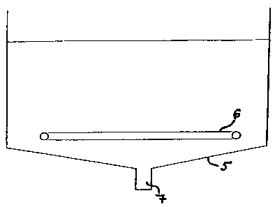
Frying vessel for a deep fryer apparatus, the frying vessel is closed with a
bottom part from the bottom and with side wall from the side, a substantially
horizontally formed electric heating element (6) which is immersed in the
frying oil and is in direct contact with the same is placed within the vessel,
and at the bottom part of the vessel an outlet (7) is provided. The bottom
part of the vessel comprises a downwardly narrowing fun-nelled portion (5),
and the outlet (7) is formed in the funnelled portion (5).


French Abstract

L'invention concerne un récipient à frire destiné à une friteuse, fermé par une partie de fond et une paroi latérale. Un élément chauffant (6) électrique sensiblement horizontal, immergé dans l'huile de friture et en contact direct avec celle-ci, est placé dans le récipient ; la partie de fond du récipient est pourvue d'un orifice de sortie (7). Ladite partie de fond comprend une partie (5) en entonnoir qui se rétrécit vers le bas, l'orifice de sortie (7) étant formé dans cette partie (5) en entonnoir.

Claims

Note: Claims are shown in the official language in which they were submitted.

Claims
1. Frying apparatus comprising a frying vessel and a drain tank (8), said
frying vessel
is closed with a bottom part from the bottom and with side wall from the side,
a
substantially horizontally formed electric heating element for being immersed
in the
frying oil and for being in contact with the same is placed within said
vessel, and at
the bottom part of said frying vessel an outlet is provided for draining off
at least the
used frying oil from the frying vessel, said bottom part of said frying vessel
comprises a downwardly narrowing funnelled portion (5), and said outlet (7) is
in
said funnelled portion (5), characterized in that said drain tank (8) is in
communication with said frying vessel through a filter (9), said tank (8) can
be
hermetically closed and opened by means of one or more air ducts (11) which
end
in a closed space being above the filling level of oil (12) when said drain
tank (8) is
filled with oil, and said drain tank (8) is located so that said filling level
of oil (12) of
the tank is lower in relation to the location of the said outlet (7), and a
pressure (A)
higher than the atmospheric pressure is introduced at least through one air
duct
(11) for feeding the frying oil back into the frying vessel via a pipe.
2. Frying apparatus according to claim 1, characterized in that said frying
vessel is
connected with the bottom of said drain tank (8) via a pipe.
3. Frying apparatus according to any one of claims 1-2, characterized in that
said
outlet (7) is provided with a stopcock (10) for closing or opening said pipe.
4. Frying apparatus according to any one of claims 1-3, characterized in that
said filter
(9) is removable and can be emptied.
5. Frying apparatus according to any one of claims 1-4 characterized in that
said
bottom part in its entirety forms said downwardly narrowing funnelled portion
(5).
6. Frying apparatus according to any one of claims 1-5 characterized in that
at least a
portion of said bottom part being directly below the substantially
horizontally formed
heating element (6) forms said downwardly narrowing funnelled portion (5).
7. Frying apparatus according to any one of claims 1-6 characterized in that
said
funnelled portion (5) is formed so that it is funnel-shaped in one dimension.

8. Frying apparatus according to any one of claims 1-6 characterized in that
said
funnelled portion (5) is formed so that it is funnel-shaped in two dimensions.
9. Frying apparatus according to any of one of claims 1-8 characterized in
that said
bottom part is formed from plane surfaces.
10. Frying apparatus according to claim 9 characterized in that said bottom
part has a
shape of a pyramid or a cone.
11. Frying apparatus according to any one of claims 1-10 characterized in that
said
funnelled portion (5) is formed asymmetrically.
12. Frying apparatus according to any one of claims 1-11 characterized in that
said
outlet (7) is formed at the bottommost point of said funnelled portion (5).

Description

Note: Descriptions are shown in the official language in which they were submitted.


CA 02546515 2006-05-17
WO 2005/063099 PCT/HU2004/000121
1
FRYING VESSEL FOR DEEP FRYER APPARATUS
The invention relates to a frying vessel for a deep fryer apparatus, where the
frying
vessel is closed with a bottom part from the bottom and with side wall from
the side, a
substantially horizontally formed electric heating element for being immersed
in the fry-
ing oil and for being contact with the same is placed within the vessel, and
at the bottom
part of the vessel an outlet is provided for draining off at least the used
frying oil.
In the technology of the food industry there are known methods for deep fat
frying,
1o especially for frying different kinds of food stuff in hot frying oil, when
the frying oil is
filled in a container which is at least closed from the bottom and the oil in
the container
is kept on appropriate temperature by means of an electric heating element,
and the
food stuff prepared for frying (e.g. potato, potato products, dough or
different kinds of
meat and meat products) is placed in the hot oil and is held there for a
certain period of
time. Examples of these methods especially for providing fried potato products
are
taught by the applicant of the present invention in U.S. Pat. No. 5,759,601
and U.S. Pat.
No. 5,974,951. In these solutions a substantially horizontally positioned
electric heating
unit in direct contact with the frying oil is located in the lower part within
the frying ves-
sel. Generally, frying takes place above the heating unit when the product
placed in a
2 o frying basket is immersed in the hot oil. In a preferred embodiment the
bottom part of
the frying vessel is equipped with an outlet which makes removal of the used
exhaust oil
possible. Then the vessel is refilled with fresh oil.
Irrespective of the benefits of the solutions proposed for controlling the
process of
frying a disadvantage of this method is that tiny pieces, fragments, crumbs,
morsels etc.
which unavoidably break off during frying settle and accumulate at the bottom
of the
vessel, and as they are very small they become burnt easily due to the
relative near-
ness of the heating unit, thereby deteriorate the quality of the oil. Then the
oil gets
spoiled in a short time.
Usually, a pump is used for draining off and refilling of the oil. It means a
further
disadvantage since the pump as a mechanical machine part may get plugged with
the
oil containing the aforementioned small fragments, and especially when the
apparatus
is not used for a relatively long time, it may obstruct the pump to such an
extent that it
needs to be disassembled to make it ready for operation again.
The aim of the present invention is to provide an apparatus in which
deterioration
of the oil caused by the small burnt fragments can be eliminated, since these
small

CA 02546515 2006-05-17
WO 2005/063099 PCT/HU2004/000121
-2-
burnt fragments can be removed in a simple manner without the need for a
delicate
piece of machinery as a pump.
The invention on the one hand is based on the realization of the fact that the
tem-
perature of the oil (which under normal frying conditions gets mixed merely as
a result
of static convection of heat) measured at different height levels
significantly decreases
in a narrow range vertically under the operating heating element. At the same
time, the
temperature above the heating element is equalized which is necessary for good
quality
frying.
On the other hand, in the range under the heating element, most of the
fragments
falling off from above will automatically roll down to the bottommost point of
the frying
vessel if the bottom part of it is inclined. Thus they will get further from
the heating ele-
ment, and due to the rapidly decreasing temperature it will get burnt to a
lesser extent.
A further advantage is that collection and removal of these fragments from the
frying oil
will be easier. Finally, by circulating the oil in two directions and by
blowing air from be-
neath, fragments which still get stuck can be broken up from the inclined
bottom part.
In one example embodiment the frying vessel for a deep fryer apparatus
according
to the invention is a vessel provided with a bottom part having a downwardly
narrowing
funnelled portion, and the outlet is formed in the funnelled portion.
Further details and advantageous embodiments of the invention will now be de-
2 o scribed with reference to the accompanying drawings in which:
Figure 1 is a diagram showing the change in temperature plotted against time
when the deep fryer apparatus is filled with oil, the heating element is in
operation and
the temperature is measured at several points in difFerent heights;
Figure 2 is a schematic drawing of one embodiment of the frying vessel
according
to the invention;
Figure 3 is a schematic drawing of another embodiment of the frying vessel ac-
cording to the invention; and
Figure 4 is a schematic drawing of one embodiment of the drain tank according
to
the invention.
3o The diagram of Figure 1 shows the change in temperature plotted against
time
when the heating element of a customary deep fryer apparatus is in operation
and the
frying vessel of the apparatus is filled with oil. Graph 1 shows the
temperature meas-
ured (starting from switching on the apparatus) in the oil at a medium height
above the

CA 02546515 2006-05-17
WO 2005/063099 PCT/HU2004/000121
-3-
heating element, graph 2 shows the temperature measured in the vicinity of the
surface.
Graph 4 shows the change in the temperature of the foodstuff placed in the oil
in a fry-
ing basket at a later point of time. In the same diagram, graph 3 shows the
temperature
of the oil measured in the apparatus below the heating element. It is
distinctly visible
that graph 3 changes much more slowly than any of the others, and it becomes
stable
at a relatively low value.
In Figure 2 an example embodiment of the frying vessel according to the
invention
is shown schematically. The frying vessel is closed at the sides by a wall and
it has a
bottom part which is formed differently from the conventional one. Within the
frying ves-
sel a horizontally shaped heating element 6 is located which is in direct
contact with the
frying oil and is typically operated by electric power. Supporting elements of
the heating
element 6 and means of the electric power supply are not shown. The bottom
part is
shaped as a downwardly narrowing funnel 5. An outlet 7 is formed at a lower
part of the
funnel 5. In this example the entire bottom part forms the downwardly
narrowing funnel
5, however, it is possible to form this funnel only at a portion of the bottom
part, the re-
mainder may be for example flat, similarly to a conventional bottom design.
Still, it is
advantageous when at least the portion of the bottom part being directly below
the es-
sentially horizontally formed heating element 6 comprises the downwardly
narrowing
funnelled portion 5.
2 o Funnelled portion 5 may be formed so that it is funnel-shaped in one
dimension,
for example when only two opposed inclined planes are used for the bottom
part. Then
outlet 7 forms a longitudinal channel, which also may be inclined. Funnelled
portion 5
may be formed so that it is funnel-shaped in two dimensions, and within this
the bottom
part may also be formed from plane surfaces, for example it may be pyramidal,
or the
vessel may be round, in which case funnelled portion 5 is a cone.
The embodiment shown in Figure 3 is similar to the one shown in Figure 2, but
in
this case funnelled portion 5 is formed asymmetrically. The advantage of this
embodi-
ment is that on the area where the most fallen off fragments (crumbs) can be
found, for
example at the point of insertion of the basket, the greater inclination of
the respective
3 o bottom part will contribute to gathering these fragments at the bottom.
In Figures 2 and 3 outlet 7 is formed at the bottommost point of the funnelled
por-
tion 5. It is noted that a crumb bag may be placed at the bottommost point,
and outlet 7
itself may be formed slightly above it.

CA 02546515 2006-05-17
WO 2005/063099 PCT/HU2004/000121
-4-
In Figure 4 outlet 7 is provided with a stopcock 10. Under the stopcock 10 a
filter 9
for filtering out the fragments (crumbs) is applied, which is removable and
can be emp-
tied. The vessel is in communication with a drain tank 8 through filter 9.
Drain tank 8 can
be hermetically closed and opened by means of one or more air ducts 11 (only
one is
shown in Figure 4) which end in the closed space being above the filling level
of oil 12
when the tank is filled with oil. Drain tank 8 should be located so that the
aforemen-
tinned filling level of oil 12 of the tank is lowered in relation to the
location of outlet 7,
stopcock 10 and filter 9, thereby draining off the frying oil becomes possible
in a simple
manner due to gravitation when stopcock 10 is opened. It is possible to raise
pressure
1o in the tank higher than atmospheric pressure by introducing compressed air
"A", by
means of which filtered frying oil may be fed back to the frying vessel via
the same
route. To this, filter 9 should be removed beforehand or at least it should be
emptied.
The system then operates as a communicating vessel controlled by pressure, and
the
exhausted frying oil can be filled or drained off without the need of a pump.
By circulat-
ing the oil in two directions and by blowing air from beneath through air duct
11, frag-
ments which still get. stuck can be broken up from the inclined bottom part,
particularly
from the part being in the vicinity of outlet 7.

Representative Drawing
A single figure which represents the drawing illustrating the invention.
Administrative Status

2024-08-01:As part of the Next Generation Patents (NGP) transition, the Canadian Patents Database (CPD) now contains a more detailed Event History, which replicates the Event Log of our new back-office solution.

Please note that "Inactive:" events refers to events no longer in use in our new back-office solution.

For a clearer understanding of the status of the application/patent presented on this page, the site Disclaimer , as well as the definitions for Patent , Event History , Maintenance Fee  and Payment History  should be consulted.

Event History

Description Date
Time Limit for Reversal Expired 2012-12-17
Letter Sent 2011-12-19
Inactive: Late MF processed 2011-05-06
Letter Sent 2010-12-17
Grant by Issuance 2010-05-18
Inactive: Cover page published 2010-05-17
Pre-grant 2010-03-03
Inactive: Final fee received 2010-03-03
Notice of Allowance is Issued 2009-09-03
Letter Sent 2009-09-03
Notice of Allowance is Issued 2009-09-03
Inactive: Approved for allowance (AFA) 2009-09-01
Amendment Received - Voluntary Amendment 2009-04-06
Inactive: S.30(2) Rules - Examiner requisition 2008-10-15
Inactive: S.29 Rules - Examiner requisition 2008-10-15
Small Entity Declaration Request Received 2007-12-17
Small Entity Declaration Determined Compliant 2007-12-17
Inactive: Cover page published 2006-08-02
Inactive: Inventor deleted 2006-07-26
Letter Sent 2006-07-26
Inactive: Acknowledgment of national entry - RFE 2006-07-26
Application Received - PCT 2006-06-13
National Entry Requirements Determined Compliant 2006-05-17
Request for Examination Requirements Determined Compliant 2006-05-17
All Requirements for Examination Determined Compliant 2006-05-17
Application Published (Open to Public Inspection) 2005-07-14

Abandonment History

There is no abandonment history.

Maintenance Fee

The last payment was received on 2009-12-15

Note : If the full payment has not been received on or before the date indicated, a further fee may be required which may be one of the following

  • the reinstatement fee;
  • the late payment fee; or
  • additional fee to reverse deemed expiry.

Please refer to the CIPO Patent Fees web page to see all current fee amounts.

Fee History

Fee Type Anniversary Year Due Date Paid Date
Basic national fee - small 2006-05-17
Request for examination - small 2006-05-17
MF (application, 2nd anniv.) - small 02 2006-12-18 2006-11-10
MF (application, 3rd anniv.) - small 03 2007-12-17 2007-12-17
MF (application, 4th anniv.) - small 04 2008-12-17 2008-12-11
MF (application, 5th anniv.) - small 05 2009-12-17 2009-12-15
Final fee - small 2010-03-03
Reversal of deemed expiry 2010-12-17 2011-05-06
MF (patent, 6th anniv.) - small 2010-12-17 2011-05-06
Owners on Record

Note: Records showing the ownership history in alphabetical order.

Current Owners on Record
LASZLO KOVACS
Past Owners on Record
None
Past Owners that do not appear in the "Owners on Record" listing will appear in other documentation within the application.
Documents

To view selected files, please enter reCAPTCHA code :


To view images, click a link in the Document Description column. To download the documents, select one or more checkboxes in the first column and then click the "Download Selected in PDF format (Zip Archive)" or the "Download Selected as Single PDF" button.

List of published and non-published patent-specific documents on the CPD .

If you have any difficulty accessing content, you can call the Client Service Centre at 1-866-997-1936 or send them an e-mail at CIPO Client Service Centre.


Document
Description 
Date
(yyyy-mm-dd) 
Number of pages   Size of Image (KB) 
Description 2006-05-17 4 230
Abstract 2006-05-17 1 50
Claims 2006-05-17 2 72
Drawings 2006-05-17 3 33
Representative drawing 2006-08-01 1 3
Cover Page 2006-08-02 1 31
Claims 2009-04-06 2 70
Cover Page 2010-04-22 2 34
Acknowledgement of Request for Examination 2006-07-26 1 177
Reminder of maintenance fee due 2006-08-21 1 110
Notice of National Entry 2006-07-26 1 201
Commissioner's Notice - Application Found Allowable 2009-09-03 1 162
Maintenance Fee Notice 2011-01-28 1 171
Late Payment Acknowledgement 2011-05-16 1 164
Maintenance Fee Notice 2012-01-30 1 171
PCT 2006-05-17 2 73
Fees 2006-11-10 1 41
Fees 2007-12-17 2 86
Correspondence 2007-12-17 2 85
Fees 2008-12-11 1 44
Fees 2009-12-15 1 38
Correspondence 2010-03-03 2 53
Fees 2011-05-06 2 50