Language selection

Search

Patent 2553722 Summary

Third-party information liability

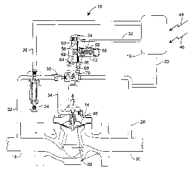
Some of the information on this Web page has been provided by external sources. The Government of Canada is not responsible for the accuracy, reliability or currency of the information supplied by external sources. Users wishing to rely upon this information should consult directly with the source of the information. Content provided by external sources is not subject to official languages, privacy and accessibility requirements.

Claims and Abstract availability

Any discrepancies in the text and image of the Claims and Abstract are due to differing posting times. Text of the Claims and Abstract are posted:

  • At the time the application is open to public inspection;
  • At the time of issue of the patent (grant).
(12) Patent: (11) CA 2553722
(54) English Title: PRESSURE LOADED PILOT VALVE SYSTEM AND METHOD FOR A REGULATOR WITHOUT ATMOSPHERIC BLEED
(54) French Title: SYSTEME DE SOUPAPE PILOTE PRESSURISEE POUR REGULATEUR SANS PURGE ATMOSPHERIQUE, ET PROCEDE CORRESPONDANT
Status: Granted and Issued
Bibliographic Data
(51) International Patent Classification (IPC):
  • G05D 16/20 (2006.01)
  • G05D 16/16 (2006.01)
(72) Inventors :
  • LAW, STEPHANIE MARIE (United States of America)
(73) Owners :
  • FISHER CONTROLS INTERNATIONAL LLC
(71) Applicants :
  • FISHER CONTROLS INTERNATIONAL LLC (United States of America)
(74) Agent: SMART & BIGGAR LP
(74) Associate agent:
(45) Issued: 2010-04-13
(86) PCT Filing Date: 2004-12-15
(87) Open to Public Inspection: 2005-08-11
Examination requested: 2006-11-15
Availability of licence: N/A
Dedicated to the Public: N/A
(25) Language of filing: English

Patent Cooperation Treaty (PCT): Yes
(86) PCT Filing Number: PCT/US2004/042083
(87) International Publication Number: WO 2005073821
(85) National Entry: 2006-07-20

(30) Application Priority Data:
Application No. Country/Territory Date
10/761,761 (United States of America) 2004-01-21

Abstracts

English Abstract


A pressure loaded pilot valve system and method for a regulator valve is
provided. The system includes a regulator valve connecting an inlet line to an
outlet line, a servo control valve assembly, and a pilot valve assembly. A
supply line is connected to the servo control valve, and a pilot loading
pressure line connects the servo control valve to the pilot valve assembly. An
exhaust line connects the servo control valve to the outlet line, thereby
avoiding waste, pollution, etc. associated with bleeding excess pilot pressure
to the atmosphere.


French Abstract

La présente invention concerne un système de soupape pilote pressurisée destiné à une soupape de régulation. Le système comprend une soupape de régulation qui relie une conduite d'entrée à une conduite de sortie, un système de soupape de servocommande, et un système de soupape pilote. Une conduite d'alimentation est reliée à la soupape de servocommande, et une conduite de pressurisation pilote relie la soupape de servocommande au système de soupape pilote. Une conduite d'évacuation relie la soupape de servocommande à la conduite de sortie, ce qui permet d'éviter la production de déchets, la pollution, etc. associées à la purge de l'excès de pression pilote vers l'atmosphère extérieure.

Claims

Note: Claims are shown in the official language in which they were submitted.

What is claimed is:
1. A pressure loaded pilot valve system for a regulator valve connecting an
inlet line
carrying fluid at an inlet pressure to an outlet line carrying fluid at an
outlet pressure, the
pressure loaded pilot valve system comprising: a servo control valve assembly;
a pilot valve
assembly; a supply line connected to the servo control valve assembly,
carrying fluid at a supply
pressure; a pilot loading pressure line connecting the servo control valve
assembly to the pilot
valve assembly, carrying fluid at a pilot loading pressure; and an exhaust
line connecting the
servo control valve assembly to the outlet line, the exhaust line carrying
fluid at an exhaust
pressure from the servo control valve assembly to the outlet line, wherein the
pilot valve opens
as the pilot loading pressure increases, and a spring bias in the pilot valve
assembly opposes the
pilot loading pressure.
2. The pressure loaded pilot valve system of claim 1, wherein the servo
control valve
assembly includes an electronic control unit that is operatively connected to
a supply pressure
solenoid valve.
3. The pressure loaded pilot valve system of claim 2, wherein the electronic
control unit is
operatively connected to an exhaust pressure solenoid valve.
4. The pressure loaded pilot valve system of claim 2, wherein the electronic
control unit is
operatively connected to a loading pressure transducer.
5. The pressure loaded pilot valve system of claim 1, wherein the pilot valve
includes a
spring to close configuration.
6. A pressure loaded pilot valve system for a regulator valve connecting an
inlet line
carrying fluid at an inlet pressure to an outlet line carrying fluid at an
outlet pressure, the
pressure loaded pilot valve system comprising: a servo control valve assembly;
a pilot valve

assembly, including a pilot valve plug movable between a closed position and
an open position, a
pilot valve diaphragm operatively connected to the pilot valve plug and
attached to a pilot valve
puller post, and a pilot valve spring configured to urge the pilot valve
puller post and the pilot
valve diaphragm in a direction so as to urge the pilot valve plug toward the
closed position; a
supply line connected to the servo control valve assembly, carrying fluid at a
supply pressure; a
pilot loading pressure line connecting the servo control valve assembly to the
pilot valve
assembly, carrying fluid at a pilot loading pressure; and an exhaust line
connecting the servo
control valve assembly to the outlet line, carrying fluid at an exhaust
pressure, wherein the pilot
valve opens as the pilot loading pressure increases, and the pilot valve
spring produces a spring
force that opposes the pilot loading pressure.
7. The pressure loaded pilot valve system of claim 6, wherein the servo
control valve
assembly includes an electronic control unit that is operatively connected to
a supply pressure
solenoid valve.
8. The pressure loaded pilot valve system of claim 7, wherein the electronic
control unit is
operatively connected to an exhaust pressure solenoid valve.
9. The pressure loaded pilot valve system of claim 7, wherein the electronic
control unit is
operatively connected to a loading pressure transducer.
6

Description

Note: Descriptions are shown in the official language in which they were submitted.


CA 02553722 2006-07-20
WO 2005/073821 PCT/US2004/042083
PRESSURE LOADED PILOT VALVE SYSTEM AND METHOD FOR A REGULATOR WITHOUT
ATMOSPHERIC BLEED
FIELD OF THE DISCLOSURE
[0001] This disclosure is related generally to methods and apparatuses for
controlling regulators and, more particularly, to improvements in systems and
methods for operating pressure loaded pilot valves for regulators.
BACKGROUND OF THE INVENTION
[0002] Fluid handling systems that include regulators often include a pilot
valve to facilitate control over the regulator. Often, the fluid used in the
pilot
valve is the same fluid that is being controlled by the regulator. For
example,
if the fluid being handled by the regulator is natural gas, a portion of
natural
gas may be diverted to be used in the pilot valve to control the regulator.
Loading pressure in the pilot valve is used to adjust the set point of the
system.
The loading pressure must be reduced when the set point needs to be lowered.
Many systems accomplish this by bleeding excess fluid to the atmosphere.
However, bleeding excess fluid to the atmosphere may be undesirable in some
situations, such as when natural gas is used as a loading pressure fluid for
the
pilot valve, because of possible adverse environmental effects, and/or the
additional risk of fire, if the bleeding of excess fluid occurs in a confined
area.
SUMMARY OF THE INVENTION
[0003] A pressure loaded pilot valve system for a regulator valve includes a
regulator valve connecting an inlet line carrying fluid at an inlet pressure
to an
outlet line carrying fluid at an outlet delivery pressure. The system further
includes a servo control valve assembly, a pilot valve assembly, a supply line
connected to the servo control valve assembly, carrying fluid at a supply
pressure; and a pilot loading pressure line connecting the servo control valve
assembly to the pilot valve assembly, carrying fluid at a pilot loading
pressure.
An exhaust line connects the servo control valve assembly to the outlet line,
carrying fluid at an exhaust pressure.
BRIEF DESCRIPTION OF THE DRAWINGS
[0004] FIG. 1 is a schematic representation of a pressure loaded pilot valve
system for a regulator valve; and

CA 02553722 2006-07-20
WO 2005/073821 PCT/US2004/042083
[0005] FIG. 2 is an enlarged schematic view of a servo control valve
assembly that may be used in the system depicted in FIG. 1.
DETAILED DESCRIPTION
[0006] With reference initially to FIG. 1, a pressure loaded pilot valve
system, generally indicated at 10, includes a pilot valve 12 operatively
connected to a regulator valve 14 and a servo control valve assembly 16. The
servo control valve assembly 16 may include a commercially available servo
control valve, such as the QB2T servo control valve, available from
Proportion-Air, Inc.
[0007] A main supply line 18 provides fluid flow at a supply pressure level
to the regulator valve 14, and a main outlet line 20 leads from the regulator
valve 14 and carries fluid at an outlet delivery pressure. A pilot supply line
22
connects the main supply line 18 to the servo control valve assembly 16.
(0008] A filter assembly 24, that may include a water separation capability,
may be connected to the supply line 22 and the servo control valve assembly
16 by a servo supply line 26. A pilot control line 28 may connect the pilot
valve 12 to the main outlet line 20 and may also be connected to the servo
control valve assembly 16 by a servo exhaust line 30. A pilot loading pressure
line 32 connects the servo control valve assembly 16 to the pilot valve 12,
and
a main valve loading pressure line 34 connects the pilot valve 12 to the
regulator valve 14. A fixed restrictor 35 may be provided between the filter
assembly 24 and the main valve loading pressure line 34.
[0009] With reference to FIG. 2, the servo control valve assembly 16 may
include an electronic control unit 36, that may be operatively connected to a
supply pressure solenoid valve 38, an exhaust pressure solenoid valve 40, and
a loading pressure transducer 42. Each of the solenoid valves 38 and 40 may
be a two-way normally closed solenoid valve. The loading pressure
transducer 42 senses the loading pressure in the pilot loading pressure line
32.
The servo control valve assembly 16 may be provided with external control
signals through a control cable 44 and may be provided power through a
power cable 46.
[0010] In operation, the pressure loaded pilot valve system 10 may operate
as follows. The pilot valve 12, which may be a spring-to-close device, is used
2

CA 02553722 2006-07-20
WO 2005/073821 PCT/US2004/042083
to actuate the regulator valve 14. For example, the regulator valve 14 may
include a diaphragm 48 that is operatively connected to a valve plug 50, and
the pilot valve 12 may be used to adjust the fluid pressure in the main valve
loading pressure line 34.
[0011] More specifically, the pilot valve 12 may include a pilot valve spring
52, surrounding a pilot valve puller post 54. The pilot valve spring 52 may be
adjusted to a desired bias set point. The pilot valve spring 52 may be placed
in
compression between a stationary cup-shaped portion 56 of the pilot valve 12
and an adjustable stop-nut 58 that may threadably attached to the pilot valve
puller post 54. The pilot valve puller post 54 may be attached to a pilot
valve
diaphragm 60 and also to a pilot bell crank lever 62. A first leg 64 of the
pilot
bell crank lever 62 is pivotally attached to the pilot valve 12 and a second
leg
66 of the bell crank lever 62 is pivotally attached to a pilot valve stem 68
that
carnes a pilot valve plug 70.
[0012] With the aforementioned arrangement, the pilot valve spring 52
urges the pilot valve puller post 54 and the pilot valve diaphragm 60 to the
right as oriented in FIG. 1, thus urging the pilot valve plug 70 toward a
closed
position, via the pilot bell crank lever 62 and the pilot valve stem 68. If
sufficient fluid pressure is applied through the pilot loading pressure line
32 to
the pilot valve diaphragm 60, the pilot valve diaphragm 60 urges the pilot
valve puller post 54 to the left as oriented in FIG. l, thus urging the pilot
valve
plug 70 toward an open position, via the pilot bell crank lever 62 and the
pilot
valve stem 68.
[0013] The fluid pressure in the pilot loading pressure line 32 may be
adjusted to a desired set point of the pressure loaded pilot valve system 10.
The fluid pressure in the pilot loading pressure line 32 may be used to
overcome the spring setting of the pilot valve 12, and thus the fluid pressure
in
the pilot loading pressure line 32 will be greater than the fluid pressure in
each
of the main outlet line 20, the pilot control line 28, and the servo exhaust
line
30. When the set point needs to be lowered, excess pressure in the pilot
loading pressure line 32 may be vented by opening the exhaust pressure
solenoid valve 40. Rather than bleeding this fluid to the atmosphere, which is
undesirable, due to waste, pollution, etc., especially when natural gas is
used

CA 02553722 2006-07-20
WO 2005/073821 PCT/US2004/042083
as a working fluid, it may be sent downstream into the main outlet line 20 via
the servo exhaust line 30.
[0014] For example, if the pilot set point is less than zero (vacuum) the
pilot
loading pressure will overcome the spring force to control the downstream
pressure at a positive pressure. Specifically, if the spring set point is
minus 5
psig and the loading pressure is 15 psig, then the control outlet pressure
would
be 10 psig.
[0015] While the present invention has been described with reference to
specific examples, which are intended to be illustrative only and not to be
limiting of the invention, it will be apparent of those ordinary skill in the
art
that changes, additions, or deletions may be made to the disclosed
embodiments without departing from the spirit and scope of the invention.
[0016] For example, if desired, the servo control valve assembly 16 may be -'
combined with the pilot valve 12 into a complete package.
4

Representative Drawing
A single figure which represents the drawing illustrating the invention.
Administrative Status

2024-08-01:As part of the Next Generation Patents (NGP) transition, the Canadian Patents Database (CPD) now contains a more detailed Event History, which replicates the Event Log of our new back-office solution.

Please note that "Inactive:" events refers to events no longer in use in our new back-office solution.

For a clearer understanding of the status of the application/patent presented on this page, the site Disclaimer , as well as the definitions for Patent , Event History , Maintenance Fee  and Payment History  should be consulted.

Event History

Description Date
Common Representative Appointed 2019-10-30
Change of Address or Method of Correspondence Request Received 2018-01-12
Grant by Issuance 2010-04-13
Inactive: Cover page published 2010-04-12
Inactive: Final fee received 2010-01-14
Pre-grant 2010-01-14
Notice of Allowance is Issued 2009-11-04
Letter Sent 2009-11-04
Notice of Allowance is Issued 2009-11-04
Inactive: Approved for allowance (AFA) 2009-10-30
Amendment Received - Voluntary Amendment 2009-09-08
Inactive: S.30(2) Rules - Examiner requisition 2009-03-11
Letter Sent 2006-12-05
Request for Examination Requirements Determined Compliant 2006-11-15
All Requirements for Examination Determined Compliant 2006-11-15
Request for Examination Received 2006-11-15
Inactive: Cover page published 2006-09-20
Inactive: Notice - National entry - No RFE 2006-09-15
Letter Sent 2006-09-15
Application Received - PCT 2006-08-26
National Entry Requirements Determined Compliant 2006-07-20
Application Published (Open to Public Inspection) 2005-08-11

Abandonment History

There is no abandonment history.

Maintenance Fee

The last payment was received on 2009-11-13

Note : If the full payment has not been received on or before the date indicated, a further fee may be required which may be one of the following

  • the reinstatement fee;
  • the late payment fee; or
  • additional fee to reverse deemed expiry.

Please refer to the CIPO Patent Fees web page to see all current fee amounts.

Owners on Record

Note: Records showing the ownership history in alphabetical order.

Current Owners on Record
FISHER CONTROLS INTERNATIONAL LLC
Past Owners on Record
STEPHANIE MARIE LAW
Past Owners that do not appear in the "Owners on Record" listing will appear in other documentation within the application.
Documents

To view selected files, please enter reCAPTCHA code :


To view images, click a link in the Document Description column. To download the documents, select one or more checkboxes in the first column and then click the "Download Selected in PDF format (Zip Archive)" or the "Download Selected as Single PDF" button.

List of published and non-published patent-specific documents on the CPD .

If you have any difficulty accessing content, you can call the Client Service Centre at 1-866-997-1936 or send them an e-mail at CIPO Client Service Centre.


Document
Description 
Date
(yyyy-mm-dd) 
Number of pages   Size of Image (KB) 
Abstract 2006-07-20 2 66
Claims 2006-07-20 3 95
Description 2006-07-20 4 194
Representative drawing 2006-07-20 1 18
Drawings 2006-07-20 2 28
Cover Page 2006-09-20 1 43
Claims 2009-09-08 2 80
Representative drawing 2010-03-23 1 12
Cover Page 2010-03-23 1 43
Notice of National Entry 2006-09-15 1 192
Courtesy - Certificate of registration (related document(s)) 2006-09-15 1 105
Acknowledgement of Request for Examination 2006-12-05 1 178
Commissioner's Notice - Application Found Allowable 2009-11-04 1 163
PCT 2006-07-20 2 79
Fees 2007-11-13 1 30
Fees 2008-11-17 1 37
Fees 2009-11-13 1 36
Correspondence 2010-01-14 1 42