Note: Descriptions are shown in the official language in which they were submitted.
CA 02563747 2011-04-20
WO 2004/094042
PCT/US2004/012009
- 1 -
NATURAL GAS DEHYDRATOR AND SYSTEM
CROSS-REFERENCE TO RELATED APPLICATIONS
This application is related to U.S. Patent No. 3,541,763, entitled "Gas
Dehydrator", to
Heath; U.S. Patent No. 4,342,572, entitled "Thermal Circulation Gas Treater",
to Heath; U.S.
Patent No. 4,511 ,374, entitled "Gas Temperature Control System for Natural
Gas
Separator", to Heath; U.S. Patent No. 4,588,424, entitled "Fluid Pumping
System", to Heath;
U.S. Patent No. 4,689,053, entitled "Heating System with Gas Jet Driven
Circulation Flow for
High Pressure Well Head Separator", to Heath; U.S. Patent No. 5,766,313,
entitled
"Hydrocarbon Recovery System," to Heath; U.S. Patent No. 6,238,461 entitled
"Natural Gas
Dehydrator," to Heath; and U.S. Patent No. 6,364,933, entitled "Apparatus for
Use with a
Natural Gas Dehydrator," to Heath.
BACKGROUND OF THE INVENTION
Field of the Invention (Technical Field):
The present invention relates generally to an apparatus and system for use
with
natural gas dehydrators of the type used to remove water and water vapor from
a natural
gas stream having a mixture of natural gas, liquid hydrocarbons, liquid
hydrocarbon vapors,
water and water vapors. The invention is particularly directed for use in the
regulation of the
glycol and the processing of all combustible gases with natural gas
dehydrators.
Description of Related Art:
Note that the following discussion refers to a number of publications by
author(s)
and year of publication, and that due to recent publication dates certain
publications are not
to be considered as prior art vis-a-vis the present invention. Discussion of
such publications
herein is given for more
CA 02563747 2011-04-20
WO 2004/094042
PCT/US2004/012009
- 2 -
complete background and is not to be construed as an admission that such
publications are
prior art for patentability determination purposes.
An example of natural gas dehydrators is disclosed in U.S. Patent No.
6,238,461
issued May 29, 2001 and U.S. Patent No. 6,364,933 issued April 2, 2002 to
Heath. In
general, such systems comprise a separator for receiving oil and water liquids
from "wet"
(water vapor laden) gas; and a water absorber, which employs a liquid
dehydrating agent
such as glycol, for removing the water vapor from the wet gas and producing
"dry" gas
suitable for commercial usage. The glycol is continuously supplied by a pump
to the
absorber in a "dry" low-water vapor-pressure condition and is removed from the
absorber in
a "wet" high-water vapor-pressure condition. The wet glycol is continuously
removed from
the absorber and circulated through a reboiler, which includes a still column
for removing the
absorbed water from the glycol and heating the glycol to provide a new supply
of hot dry
glycol. Heating of the glycol in the reboiler is generally accomplished
through use of a gas
burner mounted in a fire tube. The hot dry glycol from the reboiler passes
through a heat
exchanger, where the hot dry glycol transfers some of its heat to incoming wet
glycol going
to the still column. The dry glycol subsequently passes to a dry glycol
storage tank. A glycol
passage is provided to enable passage of wet glycol from the absorber to the
reboiler and to
pump dry glycol from a storage tank to the absorber. Besides water, the wet
glycol going to
the still column of the reboiler of the natural gas dehydrator will contain
natural gas and
absorbed hydrocarbons, and other gaseous components.
On many dehydrators, a volume of natural gas is intentionally induced into the
reboiler in order to dry the wet glycol to a higher concentration than can be
accomplished by
simply adding heat. The process of intentionally inducing a volume of natural
gas into the
reboiler is referred to as gas stripping.
In the still column of the reboiler of the natural gas dehydrator, the water,
natural
gas, and other hydrocarbons are separated from the glycol by the pressure
reduction from
the absorber pressure to approximately atmospheric pressure in the still
column and by the
application of heat to the reboiler.
The water, natural gas, other hydrocarbons and gases contained in the wet
glycol
stream which are separated in the still column from the wet glycol are
exhausted as vapors
into the atmosphere through the atmospheric vent on the still column unless
facilities are
installed to collect and dispose of the vented vapors. The hydrocarbon vapors
released
through the still column of a natural gas dehydrator are air pollutants.
Specifically, certain
hydrocarbons such as benzene,
CA 02563747 2012-08-01
WO 2004/094042
PCT/US2004/012009
- 3 -
toluene, ethylbenzene, and xylene, commonly referred to as BTEX have been
proven to be
carcinogenic. Other gases such as hydrogen sulfide, when present, are toxic.
The gas dehydrator and systems for use with gas dehydrators disclosed in U.S.
Patent
Nos. 6,238,461, 5,766,313 and 6,364,933 offer solutions to at least some of
the problems
discussed above. The present invention provides improvements to such gas
dehydrators and
systems.
BRIEF SUMMARY OF THE INVENTION
According to the invention, there is disclosed an apparatus for use with a
natural gas
dehydrator comprising: a condenser tube to circulate wet glycol in and out of
a water exhauster;
an inlet to receive dry glycol from a reboiler; a section to hold dry glycol;
a weir system to
separate hydrocarbons from said dry glycol and to provide for the removal of
said dry glycol and
said hydrocarbons from said water exhauster; an outlet to transfer
hydrocarbons out of said
weir system; an outlet to transfer dry glycol out of said weir system,a
conduit to receive dry
glycol from a coil to release into said reboiler; and an outlet to release
condensed liquids from
said water exhauster.
The present invention relates to an apparatus for use with a natural gas
dehydrator,
and gas dehydrator systems. The preferred method, apparatus, and system of the
invention
preferably comprises providing an absorber, introducing wet glycol,
introducing dry glycol, heat
exchanging the glycol, providing a reboiler, separating gaseous hydrocarbons
from liquid
hydrocarbons, circulating wet glycol, dry glycol, gaseous hydrocarbons and
liquid
hydrocarbons, and recirculating all gaseous hydrocarbons to the reboiler and
not releasing the
gaseous hydrocarbons to the atmosphere. The preferred method further comprises
collecting
all liquid hydrocarbons.
The invention further comprises transferring wet glycol from the absorber to
enter an
emissions separator, transferring wet glycol from the emissions separator to a
heat exchanger,
transferring wet glycol from the heat exchanger to a reboiler, transferring
wet glycol from the
reboiler to a wet glycol cooler, and transferring wet glycol from the reboiler
to join the wet glycol
leaving the absorber to enter the emissions separator. The heat exchanger may
comprise a
glycol-to-glycol heat exchanger. The invention further comprises providing at
least one pump to
act upon the wet glycol and dry glycol, submerging the at least one pump in
the glycol to be
pumped. Preferably, the hydrocarbon steam is sent from the emissions separator
to the
reboiler.
CA 02563747 2012-08-01
WO 2004/094042 PCT/US2004/012009
3A
The invention preferably comprises separating the wet glycol steam leaving the
emissions separator to form a second stream of wet glycol, transferring the
second stream of
wet glycol from the emissions separator to an eductor, transferring the second
stream of wet
glycol from the eductor to the emissions separator, separating the wet glycol
after forming the
second stream of wet glycol to form a third stream of wet glycol, transferring
the third stream of
wet glycol to an overhead condenser, and transferring the third stream of wet
glycol from the
overhead condenser to the reboiler. The effluent condenser may comprise
pivotally mounted
shutters to control the effluent condenser's temperature by opening and
closing the shutters in
response to temperature change. The method may include providing a filter and
providing a
choke through which the third stream of wet glycol passes before going to the
overhead
condenser.
CA 02563747 2006-10-18
WO 2004/094042 PCT/US2004/012009
-4-
The invention further preferably comprises transferring dry glycol from the
reboiler to the heat
exchanger, transferring dry glycol from the reboiler to a dry glycol storage,
transferring dry glycol
from the dry glycol storage to a glycol-gas heat exchanger, and providing a
vent to release dry glycol
from the dry glycol storage.
The invention preferably further comprises providing a stripping column within
the reboiler,
transferring dry glycol from the stripping column to the heat exchanger,
transferring dry glycol from
the heat exchanger to the dry glycol storage, transferring dry glycol from the
dry glycol storage to a
glycol-gas heat exchanger, and providing a vent to release dry glycol from the
dry glycol storage.
The invention preferably further comprises transferring a stream of
hydrocarbons from the emissions
separator to the reboiler, separating the stream of hydrocarbons leaving the
emissions separator
before entering the reboiler to form a second stream of hydrocarbons,
transferring the second
stream of hydrocarbons to a reservoir vessel, transferring one stream of
hydrocarbons from the
reservoir vessel to the reboiler to enter the stripping column, transferring a
second stream of
hydrocarbons from the reservoir vessel to a still column within the reboiler;
and transferring a
stream of hydrocarbons from the vacuum separator to the reservoir vessel. The
invention preferably
further comprises providing a release for the stream of hydrocarbons leaving
the vacuum separator
prior to entering the reservoir vessel. Preferably, the amount of hydrocarbons
entering the reservoir
vessel is controlled in response to pressure, the volume of hydrocarbons
leaving the reservoir
vessel is controlled in response to pressure, the hydrocarbons sent from the
reservoir vessel pass
through a heat exchange coil, the hydrocarbons passing from the heat exchange
coil pass through a
pressure regulator prior to entering the stripping column within the reboiler,
and the volumes of
hydrocarbons leaving the vacuum separator, entering the reservoir vessel,
leaving the reservoir
vessel, and going to hydrocarbon storage are controlled by a pressure switch.
The invention preferably fyrther comprises providing a vacuum separator,
transferring a
hydrocarbon stream from the vacuum separator to the eductor, transferring
effluent from the reboiler
to the effluent condenser, and transferring the effluent from the effluent
condenser to the vacuum
separator. An outlet may be provided to release water from the vacuum
separator and an outlet to
release hydrocarbons from the vacuum separator.
The invention preferably further comprises providing a water exhauster,
providing a
blowcase, and providing a glycol reservoir. The invention preferably includes
transferring the wet
glycol leaving the wet glycol cooler to the water exhauster then transferring
the wet glycol join the
wet glycol leaving the absorber to enter the emissions separator.
The invention preferably further comprises transferring a condensate from the
water
exhauster to the blowcase, transferring water from the blowcase to combine
with wet glycol coming
CA 02563747 2006-10-18
WO 2004/094042 PCT/US2004/012009
-5-
from the emissions separator, and transferring hydrocarbons from the blowcase
to the vacuum
separator or to a hydrocarbon storage. The invention preferably further
comprises transferring dry
glycol from the reboiler to the water exhauster, transferring the dry glycol
from the water exhauster
to the heat exchanger, transferring the dry glycol from the heat exchanger to
the dry glycol storage,
and transferring the dry glycol from the dry glycol storage to the heat
exchanger.
The invention preferably further comprises transferring hydrocarbons from the
water
exhauster to join with a stream of hydrocarbons from the dry storage tank to
enter the blowcase,
transferring a second stream of hydrocarbons from the water exhauster to join
a stream of
hydrocarbons leaving the blowcase to enter the reboiler, and transferring a
second stream of
hydrocarbons from the blowcase to a hydrocarbon storage. The hydrocarbons are
preferably sent
from the water exhauster to join with a stream of hydrocarbons from the dry
storage tank to enter the
blowcase. Preferably, a second stream of hydrocarbons from the water exhauster
is sent to join a
stream of hydrocarbons leaving the blowcase to enter the reboiler and a second
stream of
hydrocarbons is sent from the blowcase to the vacuum separator.
The invention preferably further comprises providing a closed loop glycol
system within
which to operate the dry glycol storage tank under vacuum. Preferably, the
closed loop glycol
system comprises connecting the dry glycol storage tank to the reboiler
through at least one vent
pipe, connecting the dry glycol storage tank to the glycol reservoir with at
least one vent pipe,
connecting the dry glycol storage tank to the glycol reservoir through at
least one fill pipe, and
connecting the glycol reservoir to a pipe conveying the dry glycol from the
dry glycol storage to the
glycol-gas heat exchanger.
=
Preferably, the pressures in the blowcase, the water exhauster, and the
reboiler are equal
except when the blowcase is emptied. Preferably, water is sent from the vacuum
separator to join
with wet glycol leaving the heat exchanger to enter the reboiler. Preferably,
the volume of water
leaving the vacuum separator to join with the wet glycol is metered.
The invention preferably further comprises providing a phase flash separator,
a reboiler, a
heat exchanger, a water exhauster, a glycol cooler, an effluent condenser, a
vacuum separator, an
eductor, an emissions separator, and a dry glycol storage. The phase flash
separator may comprise
a three-phase flash separator. The heat exchanger may comprise a glycol-to-
glycol heat
exchanger. The vacuum separator may be oriented horizontally or vertically.
The invention preferably further comprise transferring wet glycol from the
absorber to enter
the flash separator, providing a valve to release hydrocarbons from the flash
separator; transferring
CA 02563747 2011-04-20
WO 2004/094042
PCT/US2004/012009
- 6 -
the wet glycol from the flash separator to the reboiler, transferring wet
glycol from the
reboiler to the heat exchanger, and transferring wet glycol from the heat
exchanger to the
reboiler.
The invention preferably further comprises transferring wet glycol from the
emissions
separator to the eductor, separating the wet glycol leaving the emissions
separator to form a
second stream of wet glycol, transferring the second stream of wet glycol from
the emissions
separator to the effluent condenser, transferring wet glycol from the effluent
condenser to the
glycol cooler, transferring wet glycol from the glycol cooler to the water
exhauster, and
transferring wet glycol from the water exhauster to the emissions separator.
The dry glycol
storage may be connected to the emissions separator to provide a glycol
charge. The
invention preferably further comprises transferring hydrocarbons from the
emissions
separator to the eductor and transferring hydrocarbons from the vacuum
separator to the
eductor.
The invention preferably further comprises merging a stream of hydrocarbons
from
the emissions separator and a stream of hydrocarbons from the flash separator
to form a
joint stream of hydrocarbons and transferring the joint stream of hydrocarbons
to the
reboiler.
The invention further comprises an apparatus for use with a natural gas
dehydrator
system comprising, an absorber, wet glycol, dry glycol, a heat exchanger, at
least one
separator apparatus, a reboiler, a condenser, and at least one circulating
apparatus for wet
glycol, dry glycol, gaseous hydrocarbons, and liquid hydrocarbons. The heat
exchanger may
comprise a glycol-to-glycol heat exchanger. Preferably, at least one of the
separator
apparatus comprises a vacuum separator. The apparatus may further comprise a
glycol
cooler, an eductor, and a glycol storage. The apparatus preferably further
comprises a water
exhauster, a blowcase, a glycol storage, and a glycol reservoir. The glycol
reservoir, dry
glycol storage, reboiler, blowcase, and water exhauster are preferably
connected with a
plurality of equalizing pipes. The apparatus preferably further comprises a
stripping column
disposed within the reboiler, a reservoir vessel, and a phase flash separator.
The phase
flash separator preferably comprises a three-phase flash separator.
The invention comprises a water exhauster apparatus for use with a natural gas
dehydrator comprising a condenser tube to circulate wet glycol in and out of
the water
exhauster, an inlet to receive dry glycol from a reboiler, a section to hold
glycol, a weir
system, an outlet to transfer hydrocarbons out of the weir system, an outlet
to transfer dry
glycol out of the weir system, a coil to circulate dry glycol from the
reboiler past the glycol in
the water exhauster's glycol holding section, a conduit to receive dry glycol
from the coil to
release into the reboiler, and an outlet to release condensed liquids from the
water
exhauster.
CA 02563747 2011-04-20
=
WO 2004/094042
PCT/US2004/012009
- 7 -
The invention preferably further comprises a blowcase apparatus for use with a
natural gas dehydrator comprising an inlet to receive condensed liquids from a
water
exhauster, a weir chamber to separate condensates, a water chamber to receive
water from
the weir chamber, a hydrocarbon chamber to receive hydrocarbons from the weir
chamber,
and a liquid level controller actuated by a level of the water in the water
chamber to send a
signal to stop the water from leaving the weir chamber and to allow gas from
an emissions
separator to enter the water chamber to evacuate the water from the water
chamber.
The evacuated water preferably is mixed with a stream of wet glycol.
Preferably, the
gas in the water chamber flows into the weir chamber until pressures in the
water chamber
and in the weir chamber equalize so that the water flows from the weir chamber
to the water
chamber, and the gas from the weir system is released into the reboiler.
Preferably, the
hydrocarbons flow into the weir chamber until pressures in the hydrocarbon
chamber and in
the weir chamber equalize to that hydrocarbons flow from the weir chamber to
the
hydrocarbon chamber, and the hydrocarbons are released from the hydrocarbon
chamber.
The hydrocarbons are preferably released from the hydrocarbon chamber are sent
to a
vacuum separator or may to hydrocarbon storage facilities.
BRIEF DESCRIPTION OF THE SEVERAL VIEWS OF THE DRAWINGS
The accompanying drawings, which are incorporated into and form a part of the
specification, illustrate one or more embodiments of the present invention
and, together with
the description, serve to explain the principles of the invention. The
drawings are only for the
purpose of illustrating one or more preferred embodiments of the invention and
are not to be
construed as limiting the invention. In the drawings:
Figure 1 is a flow diagram of one embodiment of the invention;
CA 02563747 2011-04-20
WO 2004/094042
PCT/US2004/012009
- 8 -
Figure 2 is a flow diagram of another embodiment of this invention;
Figure 3 is a flow diagram of another embodiment of this invention;
Figure 4 is a sketch of a water exhauster of this invention;
Figure 5 is a sketch of a blowcase of this invention;
Figure 6 is a flow diagram of another embodiment of this invention;
Figure 7 is a sketch of a hydrocarbon gas stripping system of this invention;
Figure 8 is a flow diagram of another embodiment of this invention;
Figure 9 is a sketch of a glycol storage and glycol reservoir of this
invention; and
Figure 10 is a flow diagram of another embodiment of this invention.
DETAILED DESCRIPTION OF THE INVENTION
The present invention is an apparatus and system for use with a natural gas
dehydrator. The gas dehydrator and systems disclosed in U.S. Patent Nos.
5,766,313,
6,238,461 and 6,364,933 are useful in understanding the present invention.
The volume and pressure of the natural gas flowing through the system of the
present invention can vary in wide ranges. Each unit is designed by those
skilled in the art to
perform at wide ranges of volume and pressure of the natural gas being
processed and
various controls have been associated with the natural gas dehydrators so that
these
dehydrators can be operated in a conventional manner by those skilled in the
art. The
operation of the various components of this invention uses conventional
apparatuses that
are normally used in the operation of a natural gas dehydrator. Therefore, the
specific
parameters associated with the operation of the various components of this
invention are
parameters known by those skilled in the art.
As shown in the drawings, in accordance with the present invention, the
natural gas
is first passed through conventional two or three-phase inlet separator 24 to
remove water
and liquid hydrocarbons therefrom. The natural gas is then fed into absorber
2, through inlet
4, so that the natural gas can flow upwardly through absorber 2. Dry glycol is
introduced
through inlet 6 and flows
CA 02563747 2006-10-18
WO 2004/094042 PCT/US2004/012009
-9-
through spaced apart bubble trays or other contact medium (not shown) in
absorber 2 and then
downwardly through absorber 2. The dry glycol functions primarily to remove
water from the natural
gas and becomes wet glycol. The treated natural gas exits through outlet 8 in
the top portion of
absorber 2 and is passed through tube side 9 of glycol-gas heat exchanger 10
and passes out as
dry, saleable natural gas through pipe 12 at relatively high pressures, for
example 50 PSIG to 1500
PSIG depending on the operating pressures of the pipeline system. It is
understood that any type of
conventional heat exchanger can be used in place of exchanger 10 illustrated
in Fig. 1.
In one configuration of the invention (see Figure 1), the wet glycol is
collected in wet glycol
sump 14 in the bottom portion of absorber 2 and contains entrained and
absorbed gases, liquid
hydrocarbons, and water and exits absorber 2 at point 16, is discharged by
control valve 17 through
filter 19 in pipe 18 to inlet 20 of reflux coil 22 located in still column 24
(explained below). The flow
of the wet glycol is controlled by a throttling liquid level control (not
shown) located in absorber 2 and
operates motor valve 17 to maintain a constant level of wet glycol in the
bottom of absorber 2. The
wet glycol flows through reflux coil 22, cooling and condensing some of the
hot vapors in the top of
still column 24. The wet glycol at inlet 20 is between approximately 90 and
120 F. and at exit 26 is
approximately 150 F. The wet glycol exits reflux coil 22 at exit 26 and flows
through pipe 28 where
at point 30 it is combined with other wet glycol (explained below) flowing
through pipe 32. A by-pass
can be provided to by-pass reflux coil 22 when desired. The combined wet
glycol flows through pipe
34 and enters inlet 36 of wet glycol cooler 38. Glycol cooler 38 may be one of
many types of
coolers. As shown in the drawings, the combined wet glycol flows through a
radiator and is cooled
by air pushed through the radiator by a fan. Preferably, the fan is driven at
a constant speed and
the amount of the cooling air passing through the radiator is controlled by a
plurality of pivotally
mounted shutters moved by suitable means, such as an air cylinder or other
devices such as a
servo motor which moves a rack to rotate each of the shutters between opened
and closed positions
such as that marketed by Al R-X-CHANGERS as MODEL 48H. In the system
illustrated in Figure 1,
the combined wet glycol exits the wet glycol cooler at a temperature of
between approximately 90
and 120 F.
The cooled combined wet glycol exits the glycol cooler 38 and flows through
pipe 40 into
inlet 42 of a three-phase emissions separator apparatus 50. Free gaseous
hydrocarbons contained
in the wet glycol are released in the three-phase emissions separator
apparatus 50 as a result of the
reduction of pressure from the pressure of the absorber of between
approximately 50 and 1500
PSIG to the pressure in the three-phase emissions separator which is between
approximately 10
and 30 PSIG and preferably about 15 PSIG. Liquid hydrocarbons are separated
from the combined
wet glycol in the three-phase emissions separator apparatus 50 by a weir
system or interface liquid
level controller (not shown) and are withdrawn through outlet 52 and flow
through control valve 54
and pipe 55 to storage (not shown) or other apparatus. The amount of the wet
glycol from the
CA 02563747 2006-10-18
WO 2004/094042 PCT/US2004/012009
-10-
combined wet glycol entering the emissions separator 50, after the gases and
liquid hydrocarbons
have been removed, is then combined with a fixed volume of wet glycol
contained in the emissions
separator 50. The fixed volume of wet glycol is continuously recirculated.
Therefore, the total
volume of wet glycol in the emissions separator may be described as at least
two portions of wet
glycol. One portion is that required to be continuously circulated through one
type of apparatus as
explained below and another portion to be passed through glycol-to-glycol heat
exchanger 64 for
heat exchange with the hot dry glycol exiting the reboiler as explained below.
From the glycol-to-
glycol heat exchanger the heated wet glycol flows to the still column and into
the reboiler. The
volume of wet glycol exiting emissions separator 50 to enter the glycol-to-
glycol heat exchanger 64
is about the same volume as the volume of glycol being pumped into absorber 2
by glycol pump 76
(see Figure 1). The volume of dry glycol pumped is usually in the range of 3
to 6 gallons of dry
glycol for each pound of water removed from the gas stream. The
amount of dry glycol pumped is determined in a conventional manner known to
those skilled in the
art. The volume of wet glycol flowing out of emissions separator 50 to the
glycol-to-glycol heat
exchanger 64 is controlled by control valve 53 which is controlled by a
throttling liquid level control
(not shown) located in emission separator 50.
The freed gaseous hydrocarbons exit through outlet 56 in the top portion of
the three-phase
emissions separator apparatus 50 and flow through pipe 58 into a system, such
as that described in
the United States Patent No. 5,766,313, to be used as fuel in a reboiler as
described therein.
Another portion of wet glycol passes from three-phase emissions separator 50
through pipe
60 and enters tube side 62 of glycol-to-glycol heat exchanger 64. It is
understood that any type of
heat exchanger may be used in place of the heat exchanger 64 shown in Figure
1. Another portion
of wet glycol in glycol-to-glycol heat exchanger 64 is heated by the hot dry
glycol therein and flows
from glycol-to-glycol heat exchanger 64 through pipe 66 and enters still
column 24 of conventional
reboiler 68, such as that illustrated in the '313 Patent. Another portion of
wet glycol is changed into
hot dry glycol which is then fed through pipe 70 into glycol-to-glycol heat
exchanger 64 and is cooled
by the other portion of wet glycol. The partially cooled dry glycol then
passes through pipe 72 into
dry glycol storage tank 74 from which it is pumped by pump 76 through pipe 78
into the gas to glycol
heat exchanger 10 to be further cooled by the natural gas flowing through heat
exchanger 10 and
into pipe 12.
The one portion of the wet glycol in emissions separator 50 exits through pipe
86 and enters
pump 88. The one portion of wet glycol exiting from pump 88 separates at point
90 into the first
stream of wet glycol flowing through pipe 92 and a second stream of wet glycol
flowing through pipe
94. The wet glycol in pipe 94 passes through filter 96 and then through pipe
98 into effluent
CA 02563747 2006-10-18
WO 2004/094042 PCT/US2004/012009
-11-
condenser 84. As described above, the second stream of wet glycol exits
effluent condenser 84
through pipe 32 and is combined at point 30 with the wet glycol in pipe 28.
In a second configuration of the invention, as shown in Figure 2, the wet
glycol is collected
in wet glycol sump 14 in the bottom portion of absorber 2 and contains
entrained and absorbed
gases, liquid hydrocarbons and water and exits absorber 2 at point 16. It is
discharged by control
valve 17 through filter 19 in pipe 18 to point 30 where the wet glycol from
absorber 2 combines with
cooled wet circulating glycol from glycol cooler 38 (explained below). The
flow of the wet glycol from
absorber 2 is controlled by a throttling liquid level control (not shown)
located in absorber 2 and
operates control valve 17 to maintain a constant level of wet glycol in the
bottom of absorber 2. The
combined wet glycol flows through pipe 41 into inlet 42 of three-phased
emissions separator
apparatus 50. Free gaseous hydrocarbons contained in the wet glycol from
absorber 2 are released
in three-phased emissions separator 50 as a result of the reduction of
pressure from the pressure of
the absorber of between 50 and 1500 PSIG to the pressure in three-phased
emissions separator 50
which is between 10 and 30 PSIG and preferably about 15 PSIG. Liquid
hydrocarbons are
separated from the wet glycol in three-phased emissions separator 50 by
gravity and by a weir
system or an interfacing liquid level controller (not shown) and are withdrawn
through outlet 52,
control valve 54, and pipe 55 to storage (not shown) or other apparatus. The
wet glycol entering
emissions separator 50, after the gases and liquid hydrocarbons have been
removed, is then
combined with a fixed volume of wet glycol contained in emissions separator
50. The fixed volume
of wet glycol is continuously recirculated. Therefore, the total volume of wet
glycol in the emissions
separator has at least two portions of wet glycol. One portion is that
required to be continuously
circulated (explained below) and another portion is to be passed through a
glycol-to-glycol heat
exchanger 64 for heat exchange with the hot dry glycol exiting reboiler 68
(explained below). From
glycol-to-glycol heat exchanger 64 the heated wet glycol flows to still column
24 and into reboiler 68.
The volume of wet glycol exiting emissions separator 50 through control valve
53 to enter the glycol-
to-glycol heat exchanger 64 is about the same volume as the volume of glycol
being pumped into
absorber 2 by the glycol pump 76 (see Figure 2). The volume of dry glycol
pumped is usually in the
range of 3 to 6 gallons of dry glycol for each pound of water removed from the
gas stream. The
amount of dry glycol pumped is determined in a conventional manner known to
those skilled in the
art. The volume of wet glycol flowing out of emissions separator 50 to the
glycol-to-glycol heat
exchanger 64 is controlled by control valve 53 which is controlled by an
interfacing liquid level
control (not shown) located in emissions separator 50. To overcome any
potential pressure drop, in
excess of the gas pressure in emissions separator 50, which might occur below
control valve 53 as
a result of friction drop in the glycol piping, glycol-to-glycol heat
exchanger, or other apparatus, valve
53 is located to receive glycol from the discharge of circulating pump 88 at
approximately 100 PSIG
above the pressure in emissions separator 50 (explained below).
WO 2004/094042 CA 02563747 2006-10-18 PCT/US2004/012009
-12-
The freed gaseous hydrocarbons exit through outlet 56 in the top portion of
three-phased
emissions separator apparatus 50 and flow through pipe 58 into a system such
as that described in
the United States Patent No. 5,766,313, to be used as fuel in a reboiler as
described therein.
The other portion of wet glycol passes from three-phased emissions separator
50 through
pipe 86, circulating pump 88, and pipe 61 to point 65. At point 65, the other
portion of wet glycol is
split into two streams. As described below, one stream of wet glycol flows
through pipe 92 to power
eductor 112. The second stream of wet glycol flows through pipe 94 to point 90
where the second
steam of wet glycol splits into wet glycol stream 3 and wet glycol stream 4.
Wet glycol stream 3
flows through pipe 67, control valve 53, and pipe 57 and enters tube side 62
of glycol-to-glycol heat
exchanger 64. It is understood that any type of heat exchanger may be used in
place of heat
exchanger 64 (Shown in Figure 2). Wet glycol stream 3 in glycol-to-glycol heat
exchanger 64 is
heated by the hot dry glycol therein and flows from glycol-to-glycol exchanger
64 through pipe 66
and enters still column 24 of conventional reboiler 68 such as that
illustrated in the '313 Patent
wherein the other portion of wet glycol is changed into hot dry glycol which
is then fed through pipe
70 into the shell side of glycol-to-glycol heat exchanger 64 and is cooled by
the other portion of wet
glycol. The partially cooled dry glycol than passes through pipe 72 into a dry
glycol storage tank 74
from which it is pumped by pump 76 through pipe 78 into the gas to glycol heat
exchanger 10 to be
further cooled by the natural gas flowing through heat exchanger 10 and into
pipe 12. Dry glycol
storage 74 has vent pipe 75 which vents dry glycol storage 74 to the
atmosphere. Pipe 75 is
connected to dry glycol storage 74 at point 77.
Wet glycol stream 4 flows at approximately 100 PSIG pressure created by
circulating pump
88, through pipe 95, filter 96, pipe 97, fixed choke 101 and pipe 98 to enter
the shell side of
overhead condenser 84. Fixed or variable choke 101 or a control valve actuated
by a pressure
control device can control the volume of wet glycol flowing through pipe 98.
The temperature of the
wet glycol entering the shell side of overhead condenser 84 is substantially
the same as the
temperature of the wet glycol contained in emissions separator 50. The
temperature of the wet
glycol in emissions separator 50 is maintained by a thermostat, located in
emissions separator 50,
which opens and closes shutters on glycol cooler 38 (explained below), and the
temperature of the
glycol in emissions separator 50 is normally maintained at approximately 90 to
120 degrees
Fahrenheit. Wet glycol stream 4 flows through the shell side of overhead
condenser 84 where wet
glycol stream 4 is in a heat exchange relationship with the hot effluent from
still column 24
(explained below). Wet glycol stream 4 passes from overhead condenser 84
through pipe 33 to the
inlet 20 of a reflux coil located in still column 24 (explained below). Wet
glycol stream 4 flows
through reflux coil 22 cooling and condensing some of the hot vapors in the
top of still column 24.
Wet glycol stream 4 exits reflux coil 22 at exit 26 and flows through pipe 29
to inlet 36 of wet glycol
CA 02563747 2006-10-18
WO 2004/094042 PCT/US2004/012009
-13-
cooler 38. If desired, a bypass line can be provided to bypass reflux coil 22.
Glycol cooler 38 may
be one of many types of coolers useful in accordance with the present
invention. The drawings
show the wet glycol flowing through a radiator and cooled by air pushed
through the radiator by a
fan. Preferably, the fan is driven at a constant speed and the amount of the
cooling air passing
through the radiator is controlled by a plurality of pivotally mounted
shutters moved by a suitable
means, such as an air cylinder or other devices such as a servo motor which
moves a rack to rotate
each of the shutters between opened and closed positions such as that marketed
by AIR-X-
CHANGERS as model 48H. In the system illustrated in Figure 2, cooled wet
glycol stream 4 exits
glycol cooler 38 at point 35 at a temperature of between approximately 90 and
120 degrees
Fahrenheit. From point 35 cooled wet glycol stream 4 flows through pipe 37 to
point 30 where it
combines with the wet process glycol from absorber 2 and the combined wet
glycol flows through
pipe 40 to inlet 42 of emissions separator 50.
During the standard glycol dehydration process, gases and liquid hydrocarbons
generated
by the process are routinely released to the atmosphere. The gases and liquid
hydrocarbons
released to the atmosphere are the result of gas being entrained or absorbed
in the dry glycol while
it is contacting the natural gas in the absorber. Additional gas is entrained
in the wet glycol when a
pressure actuated pump is used to pump the dry glycol into the absorber. The
entrained and
absorbed gases and hydrocarbons are released from the wet glycol at two points
in the process.
First, most of the entrained gases are released from the wet glycol in the
emissions separator by a
reduction of pressure. Second, the balance of gases, liquid hydrocarbons, and
water are
substantially released from the wet glycol by the application of heat in the
reboiler as well as by
stripping in the still column.
One of the goals of the process of this invention is to eliminate the
atmospheric pollution
and the wasting of hydrocarbon energy that now occurs in most glycol
dehydration of natural gas.
To accomplish this goal, the process collects all the combustible gaseous
vapors and liquid
hydrocarbons generated by the glycol dehydration process. The collected
combustible vapors are
sent to the burner fuel system to be used as fuel gas in heating the reboiler.
The collected liquid
hydrocarbons are routed to a liquid storage and handling system.
As stated above, the other portion of wet glycol entering reboiler 68 is
subjected to the heat
in the reboiler and an effluent is formed in still column 24. This effluent
may comprise liquid water,
liquid hydrocarbons, vaporized water, gases and vaporized hydrocarbons. These
effluents may be
treated in systems similar to those described in the '461 and '933 Patents or
by a system illustrated
in Figure 1, wherein the effluent in still column 24 exits into pipe 82 and
passes through the tube
side of effluent condenser 84 where it is cooled as described below. Effluent
condenser 84 may be
of the type illustrated in the '461 and '933 Patents. If desired, the effluent
condenser illustrated in
CA 02563747 2006-10-18
WO 2004/094042 PCT/US2004/012009
-14-
Figures 6 and 7 of the '933 Patent may be modified so that fans 234 and 252
illustrated therein may
be continuously operated and not intermittently by a thermostat as described
therein. Instead, the
control of the temperature in the effluent condenser may be controlled by
pivotally mounted shutters
located in either the exit portion or the entrance portion of the effluent
condenser. These pivotally
mounted shutters may be operated between opened and closed positions by a
servo motor, air
cylinder, or other similar device controlled by a thermostat. As shown in
Figure 2, the effluent
passes through tube side 109 of effluent condenser 84 where it is cooled to
approximately 90 to 120
degrees Fahrenheit by wet glycol entering the shell side of effluent condenser
84 via pipe 98. The
cooled effluent includes both gaseous and liquid components which are routed
to separator 102 via
pipe 100. The cooled effluent exiting effluent condenser 84 flows through pipe
100 and enters
separator 102 which is similar to the separator shown in Figures 8 and 9 of
the '933 Patent except
that it is mounted in a vertical position instead of the horizontal position.
In separator 102, the gaseous hydrocarbons are withdrawn from the upper
portion of
separator 102 through pipe 104; the liquid hydrocarbons collected in separator
102 are withdrawn
through pipe 108 and control valve 110 to the hydrocarbon storage facilities,
the water is withdrawn
through pipe 118 and control valve 121 to disposal. The first stream of wet
glycol passing through
eductor 112 creates a vacuum to draw the gaseous hydrocarbons through pipe 104
and entrains the
gaseous hydrocarbons in the first stream of wet glycol. The first stream of
wet glycol passing
through eductor 112 compresses the gaseous hydrocarbons entrained therein to
the pressure
maintained in emissions separator 50 and then flows through pipe 114 into
emissions separator 50
wherein the gaseous hydrocarbons separate from the first stream of wet glycol
and flow with the
freed gaseous hydrocarbons through pipe 58 to the fuel system. Although other
types of devices
may be used to create the vacuum and compress the gases, an eductor is the
preferred device to
be used in the present invention.
Figures 3 to 5 illustrate another embodiment of the present invention. These
Figures
incorporate a large part of Figure 2 wherein the same reference numerals have
been applied to
corresponding parts of Figure 2. In Figures 3 to 5, there is illustrated an
embodiment of the
invention wherein additional water is removed from the dry glycol in pipe 70
to make super dry
glycol.
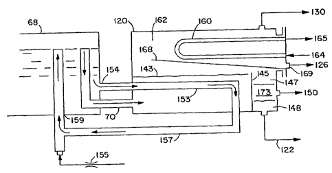
As illustrated in Figure 3, the dry glycol in pipe 70 enters water exhauster
120 (explained
below), wherein additional water is removed from the dry glycol to make super
dry glycol which exits
water exhauster 120 and flows through pipe 122 into the shell side of glycol-
to-glycol heat
exchanger 64 and then through pipe 72 into what is now super dry glycol
storage 74. From storage
74, the super dry glycol is pumped to absorber 2 and then completes the above
described closed
loop system by returning to reboiler 68 via emissions separator 50, pipe 86,
circulating pump 88,
CA 02563747 2011-04-20
WO 2004/094042
PCT/US2004/012009
- 15 -
pipe 61, pipe 94, pipe 67, control valve 53, pipe 57, glycol-to-glycol heat
exchanger 64, and
pipe 66 to still column 24.
The cooled, wet glycol exits glycol cooler 38 at point 35 and flows through
pipe 44 to
inlet 164 of a condenser tube bundle 160 mounted in water exhauster 120, as
described
below, to condense some of the vapors in the vapor section of water exhauster
120. The
condensate (mainly water and some hydrocarbons) is transmitted to blowcase 124
through
pipe 126. Blowcase 124 has a weir system that separates the condensate into
its water and
hydrocarbon components. Water from blowcase 124 is discharged by control valve
178 into
pipe 128 to combine at point 59 with the wet glycol flowing in pipe 57.
Control valve 178 is
controlled by a liquid level control (not shown) mounted in water chamber 172
of blowcase
124. Hydrocarbons from blowcase 124 (see Fig. 5) are preferably discharged by
control
valve 188 through pipe 113 into hydrocarbon chamber 111 of vacuum separator
102. In
some applications, the hydrocarbons are dumped directly to the hydrocarbon
storage.
Control valve 188 is controlled by a liquid level control (not shown) mounted
in hydrocarbon
chamber 184 of blowcase 124.
Except during the dumping cycle of blowcase 124, the pressure in blowcase 124,
water exhauster 120 and reboiler 68 is the same. The equal pressure in
blowcase 124, water
exhauster 120 and reboiler 68 is established and maintained by connecting
equalizing pipes
130 and 134 to inlet 136 of still column 24.
Water exhauster 120, blowcase 124 and the flow of fluids is preferably as
illustrated
in Figures 4 and 5; however, other systems, such as those described in United
States Patent
Nos. 3,589,984 and 4,332,643. As illustrated in Figure 4, dry glycol at about
390 F having a
glycol concentration of approximately 98.6 percent weight concentration exits
reboiler 68
through pipe 70 to water exhauster 120. Dry glycol 143 in water exhauster 120
is retained for
about thirty (30) minutes and is changed, as described below, into super dry
glycol that flows
over dam 145 into weir system 147 which separates any entrained oil and the
super dry
glycol. Super dry glycol 148, having a glycol concentration of about 99.8
percent weight
concentration, exits water exhauster 120 into pipe 122 and flows through the
shell side of the
glycol-to-glycol heat exchange 64 and thereafter flows as described above.
Free oil 173 exits
weir system 147 of water exhauster 120 through pipe 150 and pipe 149 and
enters through
inlet 151, the weir section 190 of blowcase 124 (explained below).
Dry glycol 143 in water exhauster 120 is maintained at approximately 390 F by
thermo jet coil 153 which is connected to reboiler 68 at point 154. Thermo jet
coil 153
continuously circulates hot dry glycol out of reboiler 68. The thermo jet
utilizes a small
volume of the recovered gas from
CA 02563747 2006-10-18
WO 2004/094042 PCT/US2004/012009
-16-
emissions separator 50 flowing through a small orifice 155 to create a flow of
hot dry glycol through
coil 153. The hot dry glycol flows through thermo-iet coil 153 and returns to
reboiler 68 through pipe
157 and enters reboiler 68 at point 159.
The cooled, wet glycol flows from outlet 35 of glycol cooler 38 through pipe
44 to inlet 164 of
water exhauster 120. The cooled, wet glycol, at a temperature of between
approximately 90 to 120
degrees Fahrenheit, enters condenser tube bundle 160 at point 164 and exits at
point 165. From
point 165, the cooled wet glycol flows through pipe 163 to point 30 where it
combines with the
process glycol from absorber 2, and, as previously described, from point 30,
the cooled wet glycol
flows through pipe 41 to inlet 42 of emissions separator 50. The relatively
cool wet glycol flowing
through condenser tube bundle 160 cools the vapors in vapor section 162.
Cooling of the vapors in
vapor section 162 results in the condensation of some of the vapors in vapor
section 162 changing
the partial pressure equilibrium of the various vapor components in vapor
section 162. The vapors
in vapor section 162 generally include four components comprising water,
glycol and condensable
and non-condensable hydrocarbons. Since water has a relatively low boiling
temperature compared
to glycol, it has a greater vapor pressure than glycol and is the largest
component of the vapors in
vapor section 162. Liquids condensed from vapor section 162 are collected on
collection tray 168
and removed from water exhauster 120 at point 169. Condensation of the vapors
and the removal
of the condensed liquids from water exhauster 120 continually changes the
partial pressure
equilibrium of the vapors in vapor section 162 and causes the liquid
components (glycol, water and
hydrocarbons) in dry glycol 143 in water exhauster 120 to react to re-
establish their percentage of
the equilibrium vapor pressure in vapor section 162. Being the largest
component of the vapors in
vapor section 162, water is the largest component condensed and is the primary
component evolved
from hot dry glycol 143 while re-establishing the partial pressure equilibrium
of the vapors in vapor
section 162. Therefore, the body of hot dry glycol 143 in water exhauster 120
becomes increasingly
water dry so that super dry glycol flows from weir system 147 into pipe 122.
The condensed liquids collected on collection tray 168 of water exhauster 120,
removed via
point 169 and line 126, are routed to three-phasing weir chamber 190 of
blowcase 124. Three-
phasing chamber 190 separates the condensates from water exhauster 120 into
water and
hydrocarbon components and, through a weir system, routes the water through
valve 182 into water
chamber 172 and the hydrocarbons through valve 176 into hydrocarbon chamber
184 of blowcase
124. Vent pipe 130, vent pipe 134, and vent pipe 250 equalize the pressure in
water exhauster 120,
blowcase 124, dry glycol storage 74, and glycol reservoir vessel 244 with the
pressure in reboiler 68
by connecting into still column 24 at point 136.
Referring to Figure 5, when the water level in chamber 172 of blowcase 124
reaches a level
to actuate liquid level controller 174, a pressure signal is sent to close
normally opened valve 182
CA 02563747 2006-10-18
WO 2004/094042 PCT/US2004/012009
-17-
and to open normally closed valves 178 and 180. Closing valve 182 temporarily
stops the transfer
of water from three-phasing chamber 190 into water chamber 172. Opening valve
180 allows
recovered gas from emissions separator 50 to enter water chamber 172 to
provide the pressure
energy to partially evacuate water chamber 172 through water dump valve 178
and line 128. The
evacuated water is mixed and entrained into the wet glycol in line 57 before
the wet glycol enters
tube side 62 of glycol-to-glycol heat exchanger 64. When the water level
lowers to a preset level,
liquid level controller 174 vents pressure signal and valves 182, 178, and 180
return to their normal
positions. The gas in water chamber 172 flows through normally opened valve
182 into three-
phasing chamber 190. Once the pressure in water chamber 172 and three-phasing
chamber 190
equalizes, water again begins to flow from three-phasing chamber 190 into
water chamber 172.
The power gas, which was released into three-phasing chamber 190, passes from
outlet 175
through equalizing pipes 134, and 130 into an inlet 136 of still column 24.
The operation of hydrocarbon chamber 184 mirrors the operation of water
chamber 172.
Liquid level controller 181 operates the same as liquid level controller 174.
Normally opened valve
176 operates the same as normally opened valve 182. Normally closed valves 188
and 189 operate
the same as normally closed valves 178 and 180. The hydrocarbons dumped
through valve 188 are
preferably transferred through pipe 113 to hydrocarbon chamber 111 of vacuum
separator 102. In
some applications, the hydrocarbons dumped from hydrocarbon chamber will be
transferred directly
to the oil storage facilities.
Figure 6 discloses another embodiment of the invention. Figure 6 incorporates
a large part
of Figure 2 wherein the same reference numerals have been applied to
corresponding parts of
Figure 2. In Figure 6, there is illustrated another embodiment of the
invention wherein additional
water is removed from the hot, dry glycol as the hot, dry glycol is exiting
reboiler 68 through packed
stripping column 237 mounted in reboiler 68. As illustrated in Figure 6, hot,
dry glycol at
approximately 98.6 percent weight concentration exits reboiler 68 and flows
downwardly through
packed stripping column 237. While flowing downwardly through packed stripping
column 237, the
hot, dry glycol comes into intimate contact with heated and vaporized, liquid
hydrocarbon gases that
are flowing up, counter flow to the hot dry glycol. While flowing in intimate
contact with the hot dry
glycol, the heated, liquid hydrocarbon gases "gas strip" additional water from
the hot dry glycol, and
the hot dry glycol exits, at approximately 99.8 weight concentration, from
stripping column 237. The
super dry glycol enters pipe 70 and flows through glycol-to-glycol heat
exchanger 64 and pipe 72
into super dry glycol storage 74. Super dry glycol storage 74 may be vented to
the atmosphere or
operating under a vacuum as shown in Figure 9. From glycol storage 74, the
super dry glycol is
pumped to absorber 2 and completes the above described closed loop system by
returning to
CA 02563747 2006-10-18
WO 2004/094042 PCT/US2004/012009
-18-
reboiler 68 via emissions separator 50, circulating pump 88, pipe 61, pipe 94,
pipe 67, control valve
53, pipe 57, glycol-to-glycol heat exchanger 64, and pipe 66 to still column
24.
The heated, liquid hydrocarbon gases, required to strip additional water from
the hot dry
glycol exiting reboiler 68 through packed stripping column 237, flow through
pipe 233 to the gas inlet
of stripping column 237. The heated, liquid hydrocarbon gases enter stripping
column 237 and flow
upwardly through the hot dry glycol and exit from the top of stripping column
237 into reboiler 68.
From reboiler 68 the heated, liquid hydrocarbon gases flow into still column
24 to mix with the other
gases and water vapor contained in still column 24. The total of gases
contained in still column 24
are effluents. The effluents rise to the top and exit still column 24 at point
27. As previously
described, the effluents flow, under a vacuum, through pipe 82, overhead
condenser 84 and pipe
100 into vacuum separator 102.
Overhead condenser 84 cools the effluent and most of the water. Hot,
vaporized, liquid
hydrocarbons, contained in the effluent, are changed from a vapor to a liquid
phase. The effluent
enters vacuum separator 102 and, through the weir system of vacuum separator
102, are
transferred to hydrocarbon chamber 111 of vacuum separator 102. Most of the
liquid hydrocarbons
transferred to hydrocarbon chamber 111 are again used in a closed loop system
(described below),
to strip additional water out of the hot glycol flowing out of reboiler 68
through stripping column 237.
The heated, liquid hydrocarbon gases used in stripping column 237 to remove
additional
water from hot glycol exiting reboiler 68, are obtained by heating a portion
of the hydrocarbon liquids
which have been recovered as previously described, in hydrocarbon chamber 111
of vacuum
separator 102. Referring to Figure 7, when the level of hydrocarbons in
hydrocarbon chamber 111
reach the high level set point of snap acting liquid control 192, liquid level
control 192 sends a
pressure signal to the common port of three-way pressure switch 194 such as
supplied by Wellmark,
Inc. Three-way pressure switch 194 is actuated by an adjustable spring working
against a pressure-
loaded diaphragm. The pressure to load the diaphragm of pressure switch 194 is
supplied by
throttling liquid level control 196 mounted in hydrocarbon reservoir vessel
198. The throttling liquid
level control 196 maintains a relatively fixed level of hydrocarbons in
reservoir vessel 198 by
increasing or decreasing the pressure signal being sent to three-way pressure
switch 194. As the
liquid level control 196 senses the level in reservoir vessel 198 needs to be
raised, it increases the
pressure signal to three-way pressure switch 194 shifting the three-way switch
to open port 202 and
close port 200. When the level in reservoir vessel 198 rises to the high level
set point, the output of
liquid level control 196 decreases to where three-way pressure switch 194
reverses and port 202
closes and port 200 opens.
CA 02563747 2006-10-18
WO 2004/094042 PCT/US2004/012009
-19-
When port 202 of three-way pressure switch 194 is opened and port 200 is
closed, any
hydrocarbons being dumped from hydrocarbon chamber 111 of vacuum vessel 102 by
liquid level
control 192 are routed to hydrocarbon reservoir vessel 198 through pipe 204,
pipe 206, control valve
208, and pipe 210. When port 200 of three-way pressure switch 194 is opened
and port 202 is
closed, any hydrocarbons being dumped from the hydrocarbon chamber 111 of
vacuum vessel 102
by liquid level control 192 are routed to storage (not shown) through pipe
204, pipe 212, control
valve 214, and pipe 216. By only transferring recovered liquid hydrocarbons to
storage when
reservoir vessel 198 is operationally full, the previously described system
insures that there is
always enough liquid hydrocarbons in reservoir vessel 198 to operate the
hydrocarbon stripping
system.
Reservoir vessel 198 is maintained at a pressure of between approximately 5
and 10
pounds lower than the pressure used to evacuate hydrocarbon chamber 111 of
vacuum vessel 102.
Back-pressure regulator 238, which is connected to reservoir vessel 198 by
line 236, is set to
relieve, through pipe 240, any pressure in reservoir vessel 198 that is in
excess of the high pressure
set point. The gases that are released from reservoir vessel 198 flow through
pipe 236, back-
pressure regulator 238 and pipe 130 to inlet 136 on still column 24. The
vented gases flow into still
column 24 where they mix with the effluents in still column 24. As previously
described, the vented
gases along with the other effluents are recovered in vacuum separator 102.
Pressure regulator
230 is set approximately 5 pounds lower then the high pressure set point on
back pressure regulator
238. When the pressure in reservoir vessel 198 drops approximately 5 pounds
below the high
pressure set point, pressure regulator 230 begins to open and either recovered
gas from emissions
separator 50 or gas from the supply gas system flows through pipe 234,
pressure regulator 230, and
pipe 232 into reservoir vessel 198. Preferably, the gas passing through
pressure regulator 230 to
maintain the low-pressure set point in reservoir 198 would, as shown, come
from the recovered gas
system.
The liquid hydrocarbons in reservoir vessel 198 are released into the
hydrocarbon stripping
system by control valve 218. Control valve 218 is operated by pressure-stat
220 such as supplied
by Kimray, Inc. Pressure-stat 220 has an adjustable spring that opposes a
pressure-loaded
diaphragm. The diaphragm of pressure-stat 220 is connected through line 226 to
pipe 224. As the
pressure rises in pipe 224, the increased pressure on the diaphragm of
pressure-stat 220 causes
pressure-stat 220 to react to decrease the pressure on the diaphragm of
control valve 218.
Decreasing the pressure on the diaphragm of control valve 218 causes control
valve 218 to partially
or completely close, decreasing or stopping the flow of hydrocarbons through
pipe 222 and control
valve 218. As the pressure in pipe 224 decreases, the decreased pressure on
the diaphragm of
pressure-stat 220 causes pressure-stat 220 to react to increase the pressure
on the diaphragm of
control valve 218. Increasing the pressure on the diaphragm of control valve
218 causes control
CA 02563747 2006-10-18
WO 2004/094042 PCT/US2004/012009
-20-
valve 218 to partially or completely open increasing the flow of hydrocarbons
through pipe 222 and
control valve 218.
From outlet 219 of control valve 218, the recovered, liquid hydrocarbons flow
through pipe
223 to the inlet of either heat exchange coil 221 mounted in reboiler 68 or a
heat exchange coil
mounted in an indirect heater (not shown). To heat the recovered, liquid
hydrocarbons on new
dehydrators, it is preferable to use heat exchange coil 221 mounted in
reboiler 68. To heat the
recovered, liquid hydrocarbons on retrofitted dehydrators, it is preferable to
use a heat exchange coil
mounted in an indirect heater (not shown). For this embodiment, the operation
of a new dehydrator
with a heat exchange coil mounted in the reboiler is described. The recovered,
liquid hydrocarbons
flow though heat exchanger coil 221 which is immersed in the hot glycol
contained in reboiler 68.
While in heat exchange relationship with the hot glycol in reboiler 68, the
recovered, liquid
hydrocarbons gain heat causing the recovered, liquid hydrocarbons to vaporize
and increase in
pressure. The hot, vaporized, liquid hydrocarbons exit heat exchanger coil 221
and flow through
pipe 224 to fixed choke 228. Fixed choke 228 is sized to pass the volume of
vaporized, liquid
hydrocarbons required to super dry hot glycol exiting stripping column 237 at
point 235. Pressure-
stat 220 controls the pressure in pipe 224 as well as allowing (within limits)
the pressure in pipe 224
to be raised or lowered to either increase or decrease the volume of
vaporized, liquid hydrocarbons
flowing through fixed choke 228. Pressure-stat 220 must be set to maintain the
maximum pressure
in pipe 224 to at least 5 psig below the minimum set pressure in hydrocarbon
reservoir 198.
The hot, vaporized, liquid hydrocarbons exit fixed choke 228 and flow through
pipe 233 to
the gas inlet of stripping column 237. As described above, the hot, vaporized,
liquid hydrocarbons
flow upwardly through the packing in stripping column 237 coming in intimate
contact with the hot
glycol which is flowing downwardly out of reboiler 68 through the packing in
stripping column 237.
While in intimate contact with the hot glycol in stripping column 237, the
hot, vaporized, liquid
hydrocarbons cause additional water to be removed from hot, dry glycol exiting
reboiler 68 and
super dry glycol exits stripping column 237 at point 235 and flow into pipe
70.
To complete the closed loop stripping system, as previously described, the
hot, vaporized,
liquid hydrocarbons flow through stripping column 237, reboiler 68, still
column 24, pipe 82,
overhead condenser 84, and pipe 100 into the weir section of vacuum separator
102 where the
condensed liquid hydrocarbons are transferred into hydrocarbon chamber 111.
From hydrocarbon
chamber 111, liquid hydrocarbons, enough to keep reservoir vessel 198
operationally full of liquid
hydrocarbons, are transferred through pipe 204, pipe 206, control valve 208,
and pipe 210 into
reservoir 198. From reservoir 198, the liquid hydrocarbons flow through pipe
222, valve 218, heat
exchange coil 221, pipe 224, fixed coke 228, and pipe 233 into the hot,
vaporized, liquid
hydrocarbon inlet of stripping column 237.
CA 02563747 2006-10-18
WO 2004/094042 PCT/US2004/012009
-21-
In some applications, where it is anticipated that high temperature gas (110
to 140 degrees
Fahrenheit) will be encountered, it may be desirable to eliminate the hot
glycol flow exiting the
absorber from the glycol flow to the glycol cooler. Eliminating hot glycol
from the absorber flowing
through the glycol cooler significantly decreases the cooling load on the
glycol cooler.
Figure 8 discloses another embodiment of the invention which eliminates the
hot glycol flow
from the absorber combining with the glycol flow to the glycol cooler. Figure
8 incorporates a large
part of Figure 3 and Figure 6 wherein the same reference numerals have been
applied to
corresponding parts of Figure 3 and Figure 6. Either of the processes to
obtain super dry glycol as
shown by Figure 3 or Figure 6 are applicable for use with the embodiment shown
in Figure 8. To
simplify the description of the embodiment shown by Figure 8, the process to
obtain super dry
glycol, as shown in Figure 3, has been selected for the description of the
embodiment shown by
Figure 8.
As illustrated in Figure 8, wet glycol is collected in wet glycol sump 14 in
the bottom portion
of absorber 2 and contains entrained and absorbed gases, liquid hydrocarbons,
and water and exits
absorber 2 at point 16. The flow of the wet glycol is controlled by a
throttling liquid level control (not
shown) located in absorber 2 which operates control valve 17 to maintain a
constant level of wet
glycol in the bottom of absorber 2. The wet glycol is discharged by control
valve 17 and flows
through pipe 13 to inlet 11 of three-phased flash separator 49.
Free gaseous hydrocarbons contained in the wet glycol are released in three-
phased flash
separator 49 as a result of the reduction of pressure from the pressure of the
absorber of between
approximately 50 and 1500 PSIG to the pressure in the three-phased flash
separator which is
generally between approximately 75 and 125 PSIG. Liquid hydrocarbons are
separated from the
wet glycol in three-phased flash separator 49 by a weir system or interface
liquid level control (not
shown) and are withdrawn through pipe 51, control valve 59 and pipe 79 to
storage (not shown) or
other apparatus. Control valve 59 is operated by a liquid level control (not
shown) mounted in three-
phase flash separator 49.
The freed gaseous hydrocarbons exit three-phased flash separator 49 and flow
through pipe
81, back-pressure regulator 85, pipe 87, pressure regulator 89, and pipe 91 to
point 47 where the
freed gaseous hydrocarbons combine with gaseous hydrocarbons from emissions
separator 50
which are flowing to point 47 through pipe 45. The operation of emissions
separator 50 is explained
below. From point 47, the combined gaseous hydrocarbons flow through pipe 58
into a system such
as that described in U.S. Patent No. 5,766,313, to be used as a fuel in a
reboiler as described
therein.
CA 02563747 2006-10-18
WO 2004/094042 PCT/US2004/012009
-22-
Backpressure regulator 85 maintains the minimum set pressure on three-phased
flash
separator 49. Pressure regulator 89 controls the maximum set pressure on
emissions separator 50.
Backpressure regulator 93 controls the maximum set pressure on three-phased
flash separator 49.
In the event the pressure in three-phased flash separator 49 builds to a point
high enough to actuate
back pressure-regulator 93, the excess pressure is relieved through pipe 91,
back-pressure
regulator 93 and pipe 101.
Wet glycol exits three-phased flash separator 49 and flows through pipe 15,
particulate filter
19, pipe 31, control valve 23 and pipe 39 to inlet 20 of reflux coil 22.
Control valve 23 is preferably
operated by an interfacing liquid level control (not shown) mounted in three-
phased flash separator
49. Wet glycol flows through reflux coil 22 cooling and condensing some of the
hot vapors in the top
of still column 24. The wet glycol at inlet 20 is between approximately 110 to
130 degrees
Fahrenheit and at the exits approximately 160 degrees Fahrenheit. The wet
glycol exits reflux coil
22 at exit 26 and flows through pipe 103 to inlet 63 of tube side 62 of glycol
heat exchanger 64. It is
understood that any type of heat exchanger may be used in place of glycol-to-
glycol heat exchanger
64. The wet glycol flowing through tube side 62 of glycol-to-glycol heat
exchanger 64 is heated by
the hot glycol therein and flows from glycol-to-glycol heat exchanger 64
through pipe 66 and enters
still column 24 of conventional reboiler 68, such as that illustrated in the
'313 Patent wherein wet
glycol is changed into hot, dry glycol which is then fed through pipe 70 into
water exhauster 120.
Water exhauster 120 and blowcase 124 operate as previously described so that
hot, super dry
glycol exits from water exhauster 120 through pipe 122, enters the shell side
of heat exchanger 64
and is cooled by the cool glycol flowing through tube side 62 of glycol-to-
glycol heat exchanger 64.
The partially cooled super dry glycol then passes through pipe 72 into a super
dry glycol storage 74
from which it is pumped by pump 76 through pipe 78 into the gas to glycol
exchanger 10 to be
further cooled by natural gas flowing through heat exchanger 10 and into pipe
12. The cooled super
dry glycol exits gas to glycol heat exchanger 10 through pipe 6 and enters
absorber 2 where it
comes into contact with wet natural gas flowing through absorber 2. After the
super dry glycol has
been contacted by wet natural gas, it collects as wet glycol in sump 14 of
absorber 2 and the closed
glycol loop has been completed.
A second closed loop system is shown by Figure 8. The second closed loop
system
incorporates all the components required to recover the effluents which exit
the still column of a
dehydrator. The major components in the second closed loop system are
emissions separator 50,
vacuum separator 102, glycol cooler 38, and overhead condenser 84.
At start up of the second closed loop system, all major components and
associated
equipment and piping composing the second closed loop system, which require a
glycol flow, are
CA 02563747 2006-10-18
WO 2004/094042 PCT/US2004/012009
-23-
charged with glycol, and, at the same time, a level of glycol is established
in emissions separator 50,
unless some of the original charge of glycol is lost through leakage or other
mechanical problems,
the glycol level in emissions separator 50 remains relatively constant. Pipe
119 facilitates making
the original charge of glycol in the second closed loop glycol system as well
as replacing any glycol
that might be lost from the second closed loop glycol system. Pipe 119 is
connected at point 122 to
discharge pipe 78 from glycol pump 76 and at point 123 to emissions separator
50. By opening a
manual valve (not shown), any glycol needed in the second closed loop glycol
system can be
pumped by pump 76 through pipe 78 and pipe 119 into emissions separator 50.
The glycol charge in the second closed loop is continuously circulated from
emissions
separator 50 by circulating pump 88. The glycol, at a pressure of
approximately 100 PSIG higher
than the pressure in emissions separator 50, flows through line 61 to point
65. At point 65 the glycol
stream splits. The first glycol stream flows through pipe 92 and provides
energy to power eductor
112 (described below). The second glycol stream flows from point 65 through
pipe 69, particulate
filter 96, pipe 97, fixed choke or other control 101, and pipe 98 to inlet 107
of the shell side of
overhead condenser 84. Fixed choke or other control 101 controls the volume of
glycol that is
flowing through pipe 98 into overhead condenser 84. The second stream of
glycol flows through the
shell side of overhead condenser 84 and cools hot effluent from still column
24. The second stream
of glycol exits overhead condenser 84 at exit 117 and flows through pipe 43 to
inlet 36 of glycol
cooler 38. The design and function of glycol cooler 38 has been previously
described. The cooled
second stream of glycol exits glycol cooler 38 at point 35 and flows through
pipe 44 to inlet 164 of
condenser tube bundle 160 mounted in water exhauster 120. Condenser tube
bundle 160 functions
as previously described to cool hot vapors in the vapor section of water
exhauster 120. The second
stream of glycol exits condenser tube bundle 160 and flows through pipe 177
where it enters
emissions separator 50 at point 42 closing the loop of the second stream of
glycol circulating in the
second closed loop.
As previously described, heat applied to the wet glycol in reboiler 68
releases effluents that
exit from still column 24 at point 27. From point 27, the effluents flow
through pipe 82, overhead
condenser 84, and pipe 100 into vacuum separator 102. The function of vacuum
separator 102 and
eductor 112 has been previously described. Emissions separator 50 has the same
function as
previously described, but since no processed glycol is being received or
discharged by emissions
separator 50, no automatic control of the glycol level in emissions separator
50 is required nor is
there any need for emissions separator 50 to be three-phased.
CA 02563747 2006-10-18
WO 2004/094042 PCT/US2004/012009
-24-
The glycol storage on most glycol dehydrators operates at atmospheric
pressure. A pipe
75, as shown in Figure 2, is generally used to vent to the atmosphere the
glycol storage of a
dehydrator. Pipe 75 is opened to the atmosphere and is connected to glycol
storage 74 at point 77.
Two problems are created when the glycol storage of a dehydrator is vented to
the
atmosphere. The first problem is that any excess glycol (more than the
capacity of the storage to
handle) that flows into the storage as a result of overfilling of the
dehydrator, upset of the process, or
malfunction of the equipment will flow out of the glycol storage through a
vent line such as pipe 75.
Depending upon how the installation of the dehydrator is designed to handle
glycol storage overfill
conditions, any glycol which overfills the storage and flows out a vent pipe
such as pipe 75 could
contaminate the environment. As a minimum, unless special accommodations have
been made,
any glycol, which flows out pipe 75, will be wasted. The second problem that
occurs when the glycol
storage of a dehydrator is vented to the atmosphere is that the hot glycol in
the storage is allowed to
contact oxygen in the air. Oxygen in contact with hot glycol will cause
degradation of the glycol.
Figure 9 shows another embodiment of the invention. Figure 9 incorporates a
large portion
of Figure 3 wherein the same reference numerals have been applied to
corresponding parts of
Figure 3. In Figure 3 there is illustrated an embodiment of the invention
wherein the glycol storage
operates under a vacuum to eliminate the problems of the glycol storage being
vented to the
atmosphere.
As illustrated in Figure 3, glycol storage 74 is connected to point 136 of
still column 24 by
vent pipe 246, vent pipe 250, vent pipe 134, and vent pipe 130. Still column
24 operates under a
vacuum. Glycol storage 74 is also connected to glycol reservoir 244 by vent
pipe 248. Glycol
storage 74 is also connected to glycol reservoir 244 by glycol fill pipe 258,
control valve 254 and
pipe 260. Glycol reservoir 244 is connected to high-pressure discharge pipe 78
by pipe 272, fixed
choke 268, pipe 274, control valve 262, and pipe 264. Operating glycol storage
74 in a closed loop
glycol system under a vacuum eliminates the problems of hot glycol coming into
contact with air and
of glycol being wasted or contaminating the environment.
As shown in Figure 9, glycol storage 74 provides the glycol to the suction of
glycol pump 76
(glycol pump 76 may be a stand alone pump or it may be a pump that is
internally mounted in the
glycol storage). It is necessary at all times to maintain, in glycol storage
74, a glycol level adequate
to provide the suction head to pump 76. To maintain the glycol level in glycol
storage 74, a reverse
acting, interface liquid level control 255 is utilized. Liquid level control
255 puts out a pressure signal
that increases as the glycol level in glycol storage 74 lowers and decreases
as the glycol level in
glycol storage 74 rises. The pressure signal from liquid level control 255 is
connected to a control
valve 254 and to a reverse acting pressure switch 256 such as a Kim ray 3 PGRA
Throttle-Reverse
Pilot. Pipe 258 connects control valve 254 to reservoir vessel 244. Pipe 260
connects control valve
CA 02563747 2006-10-18
WO 2004/094042 PCT/US2004/012009
-25-
254 to glycol storage vessel 74. The lower opening diaphragm pressure (15
PSIG) of control valve
254 is adjusted by turning jackscrew 257 to compress the diaphragm spring. As
the glycol level in
glycol storage vessel 74 lowers, the output pressure of liquid level control
255 increases. When the
output pressure of liquid level control 255 reaches 15 PSIG, control valve 254
begins to open and
control valve 254 will remain open until the output pressure of liquid level
control 254 drops below 15
PSIG. While control valve 254 is open, glycol in reservoir vessel 244 flows
through pipe 258, control
valve 254, and pipe 260 into glycol storage 74 maintaining the lower level of
glycol in storage vessel
74.
As previously described, the output from liquid interface level control 255 is
connected to
pressure switch 256 as well as control valve 254. The lower operating pressure
of pressure switch
256 is set at 5 PSIG by adjustment of jackscrew 259. When a condition exists
where more glycol
from glycol-to-glycol heat exchanger 64 enters through pipe 72 into glycol
storage 74 than pump 76
is pumping to absorber 2, the glycol level in glycol storage 74 will rise. As
the glycol level in glycol
storage 74 rises, the output pressure of liquid level control 255 decreases.
When the output
pressure of liquid level control 255 drops to 5 PSIG, pressure switch 256
outputs a throttling
pressure signal to control valve 262 beginning the opening of control valve
262.
The downstream side of control valve 262 is connected by pipe 264 to reservoir
vessel 244
at point 270. The upstream side of valve 262 is connected by pipe 266, fixed
choke 268, and pipe
272 to pump 76 high pressure (50 to 1500 PSIG) discharge pipe 78 which
supplies the lean glycol to
absorber 2. When control valve 262 is open, fixed choke 268 controls the
volume of glycol flowing
to reservoir vessel 244. Fixed choke 268 is preferably sized to allow no more
the 25% of the output
volume of pump 76 to flow from pipe 78 through valve 262 into reservoir vessel
244. As a result of
allowing some of the glycol being pumped by pump 76 to be transferred to
reservoir vessel 244
instead of entering absorber 2, the glycol overfill level in glycol storage 74
lowers. Lowering the
glycol level in glycol storage 74 causes the output pressure from liquid level
control 255 to increase.
When the output pressure from liquid level control 255 again reaches 5 PSIG,
pressure switch 256
bleeds off the pressure signal to control valve 262 and control valve 262
closes, stopping the flow of
glycol from pipe 78 into reservoir vessel 244.
Normal operation of glycol storage 74 is when the output of liquid level
control 255 is
between 5 and 15 PSIG. Opening and closing control valves 254 and 262
maintains the level in
glycol storage 74 at the normal condition where adequate glycol is supplied to
pump 76 and no hot
glycol contacts air, contaminates the environment, or is wasted. By using
interfacing liquid level
control 255, liquid hydrocarbons that might enter glycol storage vessel 74,
through contamination of
the process glycol, will not materially change the glycol level in glycol
storage 74. Liquid
hydrocarbons, which might enter glycol storage 74, would separate and float on
top of the glycol.
Over time, the liquid hydrocarbons can build to a high level on top of the
glycol in glycol storage 74,
WO 2004/094042 CA 02563747 2006-10-18PCT/US2004/012009
-26-
and any additional liquid hydrocarbons will need to be removed. As shown in
Figure 3, the outlet of
pipe 261 is located close to the top of glycol storage 74 and exits glycol
storage 74 at point 263.
The purpose of pipe 261 is to set the upper level of any liquid hydrocarbons
that might collect on top
of the glycol in glycol storage 74. Liquid hydrocarbons that exit glycol
storage 74 through outlet 263
flow through pipe 265 to point 267 where the liquid hydrocarbons combine with
the liquid
hydrocarbons from water exhauster 120. The combined stream of liquid
hydrocarbons flows
through pipe 149 to enter at point 151 into blowcase 124. As previously
described, the weir system
of blowcase 124 transfers the liquid hydrocarbons into oil chamber 184. From
oil chamber 184 the
liquid hydrocarbons are transferred to either the hydrocarbon chamber 111 of
vacuum separator 102
or to storage (not shown).
There are applications where the amount of gas, recovered by the previously
described
invention, can be more than the amount of gas required to fire the reboiler.
One example, of an
application where the amount of gas recovered by the invention might be more
than is required by
the reboiler to heat the dehydration process, is at compressor stations where
widely varying flow
rates and temperatures of the gas being processed by the absorber can create
conditions where
excess gas can be recovered. A second example, of an application where the
amount of gas
recovered by the invention might be more then is required by the reboiler to
heat the dehydration
process, is where the composition of the gas being processed by absorber 2
creates unusually high
BTU values for the recovered gas.
In applications where the amount of gas recovered by the invention is more
than is required
by the reboiler to heat the dehydration process, the excess recovered gas can
be used for other
purposes. Some of the other possible uses of the excess recovered gas are in a
plants fuel system
or the firing of other production equipment on the gas well or plant location.
In applications where there is no other use for excess gas recovered by the
invention, the
excess gas can be consumed by increasing the heat load on the reboiler. Figure
10 discloses
another embodiment of the invention. Figure 10 incorporates a large portion of
Figure 3 wherein the
same reference numerals have been applied to corresponding parts of Figure 3.
In Figure 10, there
is illustrated an embodiment of the invention whereby additional heat load,
more then the heat load
required by the dehydration process, can be applied to the reboiler.
To illustrate the present invention, the dehydration process utilizing the
invention's gas
recovery system and water exhauster system for obtaining super dry glycol has
been chosen. Any
of the other dehydration gas recovery processes previously described can be
used to illustrate the
present invention.
CA 02563747 2006-10-18
WO 2004/094042 PCT/US2004/012009
-27-
Referring to Figure 10, the components necessary to inject water into still
column 24 are
added to the flow diagram illustrated by Figure 3. Pipe 278 is connected to
outlet 276 located close
to the bottom of the recovered water section created by the weir system in
chamber 123 of vacuum
separator 102. Water flows from outlet 276 through pipe 278 to the suction
inlet of metering pump
282. Metering pump 282 may be electrically or pneumatically powered and is
designed to allow the
output volume to be varied over a wide range. From the discharge of metering
pump 282,
recovered water is pumped through pipe 284 to point 286. At point 286 the
water pumped by
metering pump 282 mixes with hot wet glycol flowing in pipe 66 from glycol-to-
glycol heat exchanger
64. The mixture of water and hot wet glycol enters still column 24 at point
288. Considering the
firing efficiency of the fire tube in reboiler 68, each pound of water
injected into still column 24
causes approximately 2000 BTU of excess gas to be consumed by reboiler 68. In
applications
where injecting the water into still column 24 is not practical, the water can
be injected directly into
reboiler 68.
The injected water at point 288 converts to steam and mixes with other
effluents in still
column 24. As previously described, the effluents exit still column 24 at
point 27 and flow through
pipe 82, overhead condenser 84, and pipe 100 into the weir section of vacuum
separator 102.
The injected water flows in a closed loop system from vacuum separator 102 to
still column
24 and overhead condenser 84, then back to vacuum separator 102. While flowing
through the
closed loop system, the injected water changes phase twice. The water exits
vacuum separator 102
as a liquid, reboiler 68 adds heat which converts the liquid to steam, and
overhead condenser 84
condenses the steam back to a liquid before the water returns to vacuum
separator 102.
The approximately 1200 BTU per pound of water that is removed from reboiler 68
by
converting the injected water to steam increases the heat load on overhead
condenser 84 by an
equal amount. By heat exchange with the glycol flowing in the shell side of
overhead condenser 84,
heat from the steam is transferred to the flowing glycol. The flowing glycol
exits overhead
condenser 84 and flows through pipe 33, reflux coil 22, and pipe 329 to glycol
cooler 38 where heat
is removed from the flowing glycol by exhausting the heat into the atmosphere.
The preceding examples can be repeated with similar success by substituting
the generically
or specifically described components and/or operating conditions of this
invention for those used in
the preceding examples.
Although the invention has been described in detail with particular reference
to these
preferred embodiments, other embodiments can achieve the same results.
Variations and
modifications of the present invention will be obvious to those skilled in the
art and it is intended to
CA 02563747 2011-04-20
WO 2004/094042 - 28 -
PCT/US2004/012009
cover in the appended claims all such modifications and equivalents.