Note: Descriptions are shown in the official language in which they were submitted.
CA 02575510 2007-01-29
WO 2005/106237 PCT/IL2004/000353
Arrangement of Joint Pacldng between the Pump-Injector (Injector)
Body and Nozzle Body, for Internal Combustion Engines.
TECHNICAL FIELD
The invention relates to the field of fuel supply systems for internal
combustion engines, specifically
to diesels and, more specifically, to their hydraulically driven pump-
injectors and to conventional
pump-injectors.
BACKGROUNll ART
In order to achieve greater fuel efficiency and lower exhaust emission, the
injection pressure in
modem diesels, especially in high-power diesels, should be increased to about
2000-2500 Bar and
more. Tlais imposes stricter requirements for the reliability of the joint
packing between the pump-
injector (or injector, hereinafter "pump-injector") body and the body of the
nozzle which in
conventional fuel systems is connected to the pump-injector body by a
tightening nut. To ensure the
required tightness of the joint packing, the specific pressures between the
adjoining surfaces of said
bodies should be 50-70% higher than the actual injection pressures. To achieve
this, the force
required to keep these bodies together is usually createdby a tightening nut,
which leads to the
increased tension in the nut itself; this may affect the nut strength, lead to
increased deformation of
the nozzle body and reduce the pump-injector reliability.
DISCLOSURE OF INVENTION
In the proposed arrangement of the joint packing between the pump-injector
body and nozzle body,
the increase of the specific pressures in the joint required at high injection
pressures is achieved not
by increasing the force of keeping said bodies together by a tightening nut,
but by reducing the
contact area of the face surfaces of the pump-injector and nozzle bodies.
In accordance with the invention, the design environment for the proposed
invention contains pump-
injector and of nozzle bodies that have flat precision sealing faces
contacting each other; the ends of
communicating high pressure channels located in said bodies, and bores for the
pins centering the
bodies reach out to the surface of said faces. In accordance with the
invention, these bodies contact
each other along the surface bounded by a contour line so that the area of
contacting surfaces that
I
CA 02575510 2007-01-29
WO 2005/106237 PCT/IL2004/000353
seal said faces is smaller than the area corresponding to the total area of
the face of the nozzle body
determined by the outer diameter of the nozzle body. In accordance with the
invention, the contour
line bounding the contacting area of the faces of the pump-injector and nozzle
bodies can be a single
closed line, or consist of individual closed sections. The distance between
points on said contour line
and the internal surface of said channels and bores made for the centering
pins should be equal or
.greater than the distance between the internal surface of the ends of high-
pressure channels in nozzle
body and the outer contour of the nozzle body face. The arrangement of joint
packing between the
pump-injector and nozzle bodies described above allows for reducing the area
of the contacting
surfaces of the joint by a factor of 1.5-2 and thus increasing the specific
pressure in the joint without
exceeding the allowable tightening force of the nut, and providing the
conditions for the required
level of sealing and reliable functioning of the joint at high injection
pressures.
SUMtVTARY OF THE INVENTION
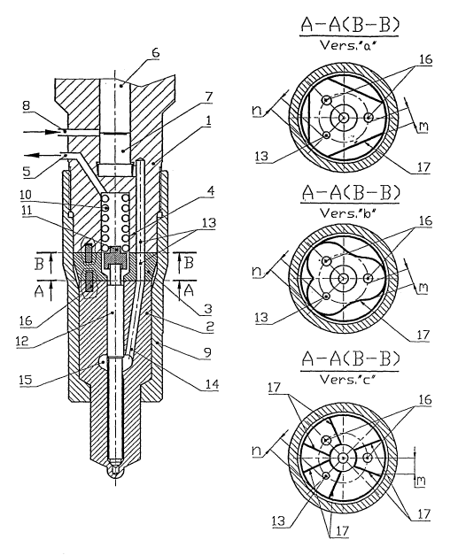
Figure 1 shows a functional diagram ofjoint packing in accordance with the
invention illustrated by
a hydraulically driven pump-injector, where (a), (b) and (c) illustrate
possible contours of the
contact surfaces of the faces of the pump-injector and nozzle bodies.
In Figure 1:1- pump-injector body; 2 - nozzle body; 3- insert between the pump-
injector and
nozzle bodies; 4- cylindrical cavity in pump-injector body 1; 5 - channel in
the pump-injector body
connecting cavity 4 with the drain tank ; 6 - plunger; 7- under-plunger
cavity; 8 - channel in the
pump-injector body, through which the under-plunger cavity is filled; 9-
tightening nut; 10 - the
return spring of the nozzle unit needle; 11 - spring support; 12 - nozzle unit
needle; 13 - channels in
pump-injector body 1 and insert 3, through which the fuel from under-plunger
cavity is supplied to
the nozzle body; 14 - channel in nozzle body through which the fuel is
supplied from channel 13
into cavity 15 of the nozzle body; 15 - cavity in nozzle body; 16 - pins
centering the bodies of the
pump-injector and nozzle with insert 3; 17- contour lines bounding the sealing
contacting surfaces
ofjoints A-A and B-B. Below the description of the lower part of hydraulically
driven pump-
injector with the arrangement of joint packing in accordance with the
invention is given.
In pump-injector body 1 in the area adjacent to insert 3, cylindrical cavity 4
is formed which
communicates with the drain tank through channel 5, plunger 6 being also
located and moving in
said body. Under-plunger cavity 7 is filled with fuel through channel 8. Pump-
injector body 1 and
nozzle body 2 are pressed to insert 3 by nut 9. In said cavity 4, return
spring 10 is disposed which
transfers the force through support to nozzle needle 12. The lower face of
insert 3 limits the
2
CA 02575510 2007-01-29
WO 2005/106237 PCT/IL2004/000353
travel of the needle which is pressed upon said face during its travel upward.
Under-plunger cavity 7
is connected via high-pressure channels 13 in body 1 of the pump-injector and
in insert 3, and also
through channel 14 in nozzle body 2 with internal cavity 15 of the nozzle
unit. The bodies of the
pump-injector and of the nozzle and the insert are centered with respect to
each other by pins 16.
Ends of channels 13 and 14, and bores of pins 16 out to the sealing surfaces
ofjoints A-A and B-B,
and the purpose of the joint packing is prevention of fuel leaks.through
abovementioned channels
and bores. Contour lines 17 bounding the contacting surfaces of the faces
shown in Figure 1(a, b, c)
are possible examples of the fonn of the contacting sealing surfaces.
BEST MODE FOR CARRYING OUT THE INVENTION
As mentioned above, the contour lines bounding the contacting surfaces of the
joint can be made
continuous (Figure la and lb), or discontinuous and discrete (dashed) (Figure
lc). The form of the
contour line should be selected based on the actual design of the bodies of
the pump-injector and
nozzle units. It should be provided that the minimum distance (bridge "m", see
Figure 1) between
the inner surface of the channels and the bores for pins coming out to the
sealing joints, and the
contour lines are equal or greater than the distance "n" (bridge "n", see
Figure 1) between said bores
and outer contour of the cylindrical nozzle body. Such limiting of the "m"
distance ensures a
reliable joint sealing at high pressures (2500 Bar and higher) which is not
less reliable than
conventional systems where the injection pressures do not exceed 1000-1200
Bar.
Providing a reduced contact area of the contacting sealing surfaces is easiest
on the pump-injector
body and on the insert. In this case, one can use conventional designs of
nozzle units and their
bodies which are manufactured using a special technology.
It will be evident to those skilled in the art that the invention is not
limited to the details of the
foregoing illustrated embodiments and that the present invention may be
embodied in other specific
forrms without departing from the spirit or essential attributes thereof. The
present embodiments are
therefore to be considered in all respect as illustrative and not restrictive,
the scope of the invention
being indicated by the appended claims rather than by the foregoing
description, and all changes
which come within the meaning and range of equivalency of the claims are
therefore intended to be
embraced therein.
3
CA 02575510 2007-01-29
WO 2005/106237 PCT/IL2004/000353
INDUSTRIAL APPLICABILITY
Arrangement of joint packing between the pump-injector (injector) body and the
nozzle body in
accordance with the invention can be used for sealing the joints both in
conventional injectors and in
pump-injectors. It is especially advisable to use the joint packing in
accordance with the invention in
hydraulically driven pump-injectors. This is because in hydraulically driven
pump-injectors, high
injection pressures are normally used (2000 Bar, which may soon increase to
2500 Bar and higher)
requiring a reliable sealing of said joint without increasing the tightening
force of the tightening nut.
The problem of sealing the joints is important because we are dealing with
larger injectors which are
typical of large diesels, such as diesels used for off-road vehicles,
locomotives, and marine
applications and have larger face areas and, consequently, larger areas of
contacting surfaces.
Therefore the joint packing in accordance with the invention should be
preferably used in diesels of
the above mentioned applications.
4