Note: Descriptions are shown in the official language in which they were submitted.
CA 02579041 2007-02-27
WO 2006/029270 PCT/US2005/032006
METHODS AND DEVICES FOR STERILE FIELD TRANSFER
RELATED APPLICATIONS
This application claims the benefit of United States Provisional Patent
Application Serial No. 60/607,631, entitled "Sterile Field Transfer Method and
Design" filed September 7, 2004, the entire contents of which are hereby
incorporated by this reference.
RELATED FIELDS
Embodiments of the present invention relate to methods and devices for
transferring at least a component of a material into a sterile vessel for use
in a
sterile field.
BACKGROUND
It is often necessary to ensure that items used in a sterile field, such as an
operating room, research & development facility, or other sterile environment,
are
themselves sterile. Instruments, devices, containers, implants and other items
intended for use in the sterile field may require sterilization and may need
to be
maintained in a sterile condition. Items that are non-sterile, or that
potentially
have contacted other non-sterile items or non-sterile persons (such as
doctors,
technicians or nurses who have come into contact with non-sterile items), may
be
unacceptable for use in the sterile field. Accordingly, doctors, nurses,
technicians
and other individuals working in or around sterile fields must follow strict
guidelines and procedures for ensuring the sterility of items brought into
and/or
used in the sterile field. Some of the current sterilization procedures and
guidelines, however, are undesirable, burdensome and inefficient.
For example, typical procedures for collecting and transporting blood
platelets into a sterile field may be undesirable, as those procedures may
require
the transfer of the platelets between a number of different containers and
devices. Typically, the nurse, technician, doctor or other individual collects
a
blood sample in a syringe. Next, he or she transfers the blood into a
centrifuge.
The centrifuge processes the blood to concentrate the blood platelets. Next,
the
1
2094280
CA 02579041 2007-02-27
WO 2006/029270 PCT/US2005/032006
concentrated blood platelets are collected into another syringe and
subsequently
transferred into a sterile cup. The sterile cup is finally brought into the
sterile field
where it can be drawn into a sterile syringe. Such a technique is undesirable,
as
it requires the blood and blood platelets to be transferred multiple times
from
vessel to vessel in a manner that is inefficient and subject to spillage or
even
accidental contamination.
Other procedures, techniques and guidelines for ensuring the sterility of
items used in sterile fields may also be undesirable, burdensome and
inefficient.
SUMMARY
Embodiments of the present invention provide safe and efficient methods
and devices for transferring a material or a component of a material from a
non-
sterile vessel or potentially non-sterile vessel into a sterile vessel, while
maintaining the sterility of the sterile vessel. Embodiments of the present
invention may be suitable for transferring a wide variety of materials or
material
components into a sterile vessel, including, but not limited to, blood, blood
components (such as platelets or blood plasma), bone cement, ceramics,
allogenic bone, autologous bone, bone marrow, other fluids, polymers,
composite
materials, nanomaterials, or any other material or material component that is
intended for use in a sterile field. Devices according to various embodiments
of
the present invention may also process the materials or material components
introduced into the device prior to or during transfer into the sterile
vessel.
Exemplary processes include, but are not limited to, filtration to separate
larger
components of a material from smaller components (e.g, filtering blood to
separate the platelets from other blood components), mixing materials
together,
separating materials, reacting various materials together, instrument
fabrication,
implant fabrication, sterilization or. any other process that may be done to a
material or a material component prior to use in a sterile field. In other
embodiments, devices of the present invention do not process the materials
introduced into them at all, but merely facilitate the material transfer into
the
sterile vessel without affecting the sterility of the sterile vessel.
2
2094280
CA 02579041 2007-02-27
WO 2006/029270 PCT/US2005/032006
Devices of the present invention may include a sterile vessel and a
housing at least partially enclosing the sterile vessel. The device housing
may
enclose the sterile vessel to protect the vessel from direct contact with
potentially
non-sterile persons and items, which could potentially affect the sterility of
the
sterile vessel and prevent use of the vessel in the sterile field. In some
embodiments, the housing may include a cover that limits access to the sterile
vessel until the cover is removed or opened. In other embodiments, such a
cover
is unnecessary.
Devices according to the present invention may also include a material
input accessible from outside the housing. The material input may facilitate
the
introduction of a material into the device, which eventually may be
transferred by
the device (or a component of the material may be transferred by the device)
into
the sterile vessel. In some embodiments, the material input interacts with a
non-
sterile syringe or other vessel external to the device. In some embodiments,
the
material input is associated with a conduit within the device that conveys the
material to various internal components of the device (such as a filter) and
to the
sterile vessel. In other embodiments, the conduit is integral with the
material
input and conveys the material directly into the sterile vessel.
Some embodiments of the present invention may also include internal
components, such as filters or other components, for processing the inputted
material. In some embodiments, the device may also include additional material
inputs and/or internal components for introducing and/or processing additional
materials in the device. The additional materials introduced may facilitate
various
processes of the device and/or may facilitate the movement of other materials
(or
components thereof) within and between various internal components of the
device. In other embodiments, the device does not include such components
and merely conveys the material directly into the sterile vessel.
In some embodiments, the device is disposed of after use and is made
with relatively inexpensive materials.
3
2094280
CA 02579041 2007-02-27
WO 2006/029270 PCT/US2005/032006
STATEMENT OF THE INVENTION
Accordingly, embodiments of the present invention provide for a device for
facilitating the transfer of at least a component of a material into a sterile
vessel,
characterized in that the device comprises: a sterile vessel; a housing at
least
partially enclosing the sterile vessel; a material input for facilitating the
input of a
material into the device, the material input accessible from outside the
housing;
and a conduit for guiding movement of at least a component of the material
from
the material input to the sterile vessel.
More preferably, embodiments of the present invention provide for a
device further characterized in that the housing comprises a cover and wherein
moving the cover facilitates accessing the sterile vessel.
Even more preferably, embodiments of the present invention provide for a
device further characterized in that the cover is at least temporarily sealed
on the
device.
Also even more preferably, embodiments of the present invention provide
for a device further characterized in that the cover comprises a removable cap
or
a moveable hatch.
Yet even more preferably, embodiments of the present invention provide
for a device further characterized in that the housing comprises an at least
semi-
transparent window.
Also even more preferably, embodiments of the present invention provide
for a device further characterized in that the housing comprises at least one
actuator for actuating at least one valve, the at least one valve for at least
partially regulating the movement of the at least a component of a material
through the conduit.
Also more preferably, embodiments of the present invention provide for a
device further characterized in that the device comprises a reservoir
associated
with the conduit.
Even more preferably, embodiments of the present invention provide for a
device further characterized in that the reservoir is associated with the
material
input and receives material from the material input.
4
2094280
CA 02579041 2007-02-27
WO 2006/029270 PCT/US2005/032006
Also more preferably, embodiments of the present invention provide for a
device further characterized in that the device comprises a filter for
separating the
component from a second component of the material.
Even more preferably, embodiments of the present invention provide for a
device further characterized in that the conduit directs the component into
the
sterile vessel.
Yet even more preferably, embodiments of the present invention provide
for a device further characterized in that the device comprises a second
material
input for receiving a second material, wherein introduction of the second
material
into the device facilitates moving the component from the filter to the
sterile
vessel.
Also yet even more preferably, embodiments of the present invention
provide for a device further characterized in that the device comprises a
second
reservoir for collecting the second component from the filter.
Other embodiments of the present invention provide for a method for
facilitating the transfer of at least a component of a material into a sterile
field,
characterized in that the method comprises: collecting a material into a
vessel;
transferring the material from the vessel into a device, characterized in that
the
device comprises: a sterile vessel; and a housing at least partially enclosing
the
sterile vessel; transporting the sterile vessel into a sterile field; and
removing the
sterile vessel from the device.
More preferably, embodiments of the present invention provide for a
method further characterized in that the sterile vessel is transported into
the
sterile field prior to removing the sterile vessel from the device.
Also more preferably, embodiments of the present invention provide for a
method further characterized in that the sterile vessel is removed from the
device
prior to transporting the sterile vessel into the sterile field.
Also more preferably, embodiments of the present invention provide for a
method further characterized in that removing the sterile vessel from the
device
comprises moving a cover of the housing of the device to access the sterile
vessel.
2094280
CA 02579041 2007-02-27
WO 2006/029270 PCT/US2005/032006
Even more preferably, embodiments of the present invention provide for a
method further characterized in that moving the cover comprises removing the
cover from the device.
Also even more preferably, embodiments of the present invention provide
for a method further characterized in that moving the cover comprises opening
a
hatch.
Also more preferably, embodiments of the present invention provide for a
method further characterized in that the method comprises filtering the
material to
separate the material into a first component and a second component.
Also more preferably, embodiments of the present invention provide for a
method further characterized in that the method comprises disposing of the
device.
BRIEF DESCRIPTION OF FIGURES
Figure 1 is a schematic of a device according to a first embodiment of the
present invention.
Figure 2 is a perspective view of a device according to another
embodiment of the present invention, shown without the device's housing.
Figure 3 is a perspective view of a device according to another
embodiment of the present invention, shown without the device's housing.
Figure 4 is a perspective view of a device according to another
embodiment of the present invention, shown without the device's housing.
Figure 5(a) is a perspective view of the exterior of a device according to
another embodiment of the present invention.
Figure 5(b) is a side view of the device of Fig. 5(a).
Figure 6(a) is a perspective view of the exterior of a device according to
another embodiment of the present invention.
Figure 6(b) is a side view of the device of Fig. 6(a).
Figure 6(c) is a rear perspective view of the device of Fig. 6(a).
Figure 7(a) is a perspective view of the exterior of a device according to
another embodiment of the present invention.
Figure 7(b) is a side view of the device of Fig. 7(a).
6
2094280
CA 02579041 2007-02-27
WO 2006/029270 PCT/US2005/032006
Figure 8(a) is a perspective view of the exterior of a device according to
another embodiment of the present invention.
Figure 8(b) is a side view of the device of Fig. 8(a).
Figure 9(a) is a perspective view of the exterior of a device according to
another embodiment of the present invention.
Figure 9(b) is a side view of the device of Fig. 9(a).
DETAILED DESCRIPTION OF FIGURES
Fig. 1 shows a device 10 in accordance with embodiments of the present
invention. In the configuration shown in Fig. 1, device 10 includes a sterile
vessel
12, a housing 14 (which includes a cover 16), a material input 18, an actuator
20,
a window 22, a second material input 24, a base 26, and a seal 100. In other
embodiments, some or all of these features are unnecessary and/or are present
in different configurations, positions, orientations, shapes and sizes.
The sterile vessel 12 shown in Fig. 1 is a syringe, however, sterile vessel
may be any vessel suitable for receiving materials or components of materials,
including test tubes, beakers, vials, IV bags, sample holders, pails, cups,
bowls,
trays, or gloved hands. Sterile vessel 12 may be sterilized prior to
installation in
device 10 or sterilized along with the rest of device 10 or components of
device
10. Sterile vessel 12 (and other components of device 10 if desired or
required)
may be sterilized in any suitable procedure or technique, including, but not
limited
to, gas sterilization or gamma radiation. In other embodiments, it is
unnecessary
to subject sterile vessel 12 and/or other components of device 10 to a
sterilization
procedure and/or the sterile vessel may have been maintained in a sterile
condition since its manufacture.
The housing 14 shown in Fig. 1 encloses sterile vessel 12. Housing 14 is
preferably formed from a plastic, such as polycarbonate, however, housing 14
may be formed from other materials if desired. In some embodiments, it is
desirable to form housing 14 (and other components of device 10) from
relatively
inexpensive materials, as device 10 may be intended to be disposable or
intended for "one time use" in some configurations.
7
2094280
CA 02579041 2007-02-27
WO 2006/029270 PCT/US2005/032006
Because the housing 14 shown in Fig. I encloses sterile vessel 12, the
sterility of vessel 12 may be preserved even if device 10 is used in non-
sterile
fields or comes into contact with non-sterile persons or things. In the
embodiment of Fig. 1, the housing 14 (which includes the cover 16 in the
configuration shown in Fig. 1) preserves the sterility of vessel 12 until such
time
as cover 16 is removed or repositioned to allow access to sterile vessel 12 by
a
sterile nurse, doctor, technician or other individual for use in a sterile
field. In
some embodiments, a non-sterile individual will remove or reposition the cover
16
and a sterile individual will remove the sterile vessel 12 such that the
vessel 12
does not contact non-sterile persons or things and such that the sterile
person
does not contact the potentially non-sterile housing 14 of device 10. In other
embodiments, device 10 may be configured to automatically move the cover 16
or otherwise facilitate access to sterile vessel 12 after the occurrence of
one or
more events. For instance, in some embodiments, the transfer or completion of
transfer of a material into sterile vessel 12 may trigger the device 10 to
automatically move the cover 16 or otherwise facilitate accessing vessel 12.
In some embodiments, one person will transport the device 10 into the
sterile field and the sterile person will remove the sterile vessel 12. In
other
embodiments, the sterile person will remove the sterile vessel 12 from the
device
outside of the sterile field, and then enter the sterile field with the
sterile vessel
12.
As shown in Fig. 1, cover 16 is a removable lid. In other embodiments, a
cover 16 similar to the one shown in Fig. I can be used in conjunction with
the
devices 10 shown in Figs. 5(a), 5(b), 7(a), 7(b), 8(a), 8(b), 9(a) and 9(b),
although
the devices 10 shown in these Figures may not necessarily require such a cover
in all embodiments. In still other embodiments, such as shown in Fig. 6(c),
cover
16 may be a hatch mounted to device 10 in a rotating fashion.
As shown in Fig. 1, cover 16 includes a removable or breakable seal 100
for indicating whether sterile vessel 12 has been previously accessed or
tampered with (indicating a potential loss of sterility). A user (in some
embodiments, the non-sterile nurse, doctor, technician or other non-sterile
individual) may break or remove the seal 100 and remove or reposition the
cover
8
2094280
CA 02579041 2007-02-27
WO 2006/029270 PCT/US2005/032006
16 to allow access to sterile vessel 12. The seal 100 may be any desired
mechanism, structure, device or item for sealing cover 16 onto device 10,
including frangible tabs, adhesive tape, gaskets, tamper indicating
mechanisms,
or any other suitable structure or mechanism for sealing cover 16 prior to
removal
or repositioning. Fig. 1 shows seal 100 as an adhesive tape at least partially
encircling the connection between cover 16 and the rest of housing 14. In
still
other embodiments, a separate mechanism, structure, device or item is not
necessary to seal cover 16 to the rest of housing 14 and the cover is formed
integrally with the rest of housing 14. In such embodiments, cover 16 may be
punctured, broken or otherwise destroyed once it is desired to access sterile
vessel 12. In other embodiments, a seal is unnecessary.
In yet other embodiments, cover 16 is unnecessary. For example, the
housing 14 may include an aperture in which sterile vessel 12 is located.
Sterile
vessel 12 may be positioned deep enough within the housing 14 such that non-
sterile persons or things cannot easily contact sterile vessel 12. In such
embodiments, device 10 may include a slider or other mechanism for
facilitating
access to the sterile vessel 12 at the appropriate time. For example, in some
embodiments, actuation of the slider may raise sterile vessel 12 into an
accessible position. In other embodiments, as the sterile vessel 12 fills with
material (described further below), a plunger of the vessel may extend outside
of
the housing, allowing a sterile nurse, doctor or technician to grasp the end
of the
plunger and remove sterile vessel 12 from device 10. In some embodiments, the
housing 14 may include a plastic film over the aperture or other portions of
the
housing 14, such that breaking the film allows access to the vessel 12.
The device 10 of Fig. 1 also includes a material input 18. As discussed
above, material may be any material that a user desires to transfer into a
sterile
vessel 12, including blood, blood components (such as platelets or blood
plasma), bone cement, ceramics, allogenic bone, autologous bone, bone marrow,
other fluids, or any other material. Material input 18 may be configured to
receive
and convey any desired material into device 10. In one embodiment, material
input 18 includes an aperture that corresponds to the size and shape of a
syringe
tip such that material input 18 receives the tip in a manner that
substantially
9
2094280
CA 02579041 2007-02-27
WO 2006/029270 PCT/US2005/032006
prevents leakage. In some embodiments, material input 18 is an aperture in
housing 14 that allows the syringe or other vessel to interact with internal
components such that the syringe can introduce material into device 10.
Material
input 18 may also include a gasket or other appropriate structures or
mechanisms for lessening the chance of leakage. In other embodiments,
material input 18 does not interact with a syringe to receive material, but is
sized,
shaped and positioned for material to be poured directly into material input
18.
For example, in some embodiments, material input 18 may be a funnel.
In still other embodiments, material input 18 may comprise other structures
or mechanisms for facilitating the input of material into device 10.
Additionally,
material input 18 may or may not include a check valve or other appropriate
structures and mechanisms for preventing material from flowing back out of
material input. In some embodiments, material input 18 may include a filter,
such
as a screen, or other structure for separating impurities or other things from
material during input into device 10.
The device 10 shown in Fig. 1 also includes an actuator 20. The actuator
20 may be a slide (such as shown in Figs. I and 5(a)), a knob, a button (such
as
shown in Figs. 6(a), 7(a), 8(a) and 9(a)) or other suitable structure or
mechanism
for commencing processes or otherwise affecting structures inside device 10,
some examples of which are discussed further below. Although Fig. 1 shows
device 10 as only including a single actuator 20, devices 10 in accordance
with
embodiments of this invention may include any number of actuators 20 for
controlling or affecting various internal components of device 10. In still
other
embodiments, an actuator 20 is unnecessary.
The device 10 of Fig. 1 also includes a window 22. In some embodiments,
window 22 may be a transparent or semi-transparent window. Window 22 may
allow viewing of one or more of the internal components of device 10 and/or
the
progress of the inputted material through the same. As shown in Figs. 1, 5(a),
6(a), 7(a), 8(a) and 9(a), the size, shape, number and position of windows 22
may be varied to facilitate viewing various interior portions and/or
components of
device 10. In other embodiments, window 22 is unnecessary and/or other
features of device 10 indicate the progress of the inputted material through
2094280
CA 02579041 2007-02-27
WO 2006/029270 PCT/US2005/032006
device 10. For example, sterile vessel 12 may include a plunger that extends
as
material fills the vessel 12, which may roughly indicate the amount of
material
that has moved into the vessel. In some embodiments, device 10 does not
include any features or components for indicating the progress of material
through device 10.
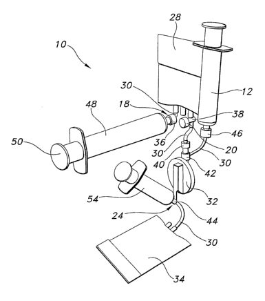
In the configuration shown in Fig. 1, device 10 includes a second material
input 24. Like embodiments of material input 18 described above, second
material input 24 may interact with the tip of a syringe 54 (shown in Figs. 2-
4) to
receive and convey a material into device 10 or may include other structures
and
mechanisms as discussed above for material input 18. Second material input 24
is also discussed further below.
In the configuration shown in Fig. 1, device 10 also includes a base 26.
Base 26 may maintain the device 10 in an upright orientation when placed on a
surface. Moreover, if desired, a user may push down on base 26 to stabilize
device 10 during use. As shown in Figs. 5(a) - 9(b), base 26 may be formed in
a
wide variety of shapes, sizes and configurations.
The devices 10 shown in Figs. 1- 9(b) are configured to separate the
platelet component of a blood material and transfer those platelets into
sterile
vessel 12. Devices 10 in accordance with other embodiments of the present
invention, however, may be configured to perform a wide variety of processes
on
a wide variety of materials. Exemplary processes include, but are not limited
to,
filtering, mixing, separating, reacting, fabrication, or sterilization. In
still other
embodiments, device 10 does not process the inputted material at all, but
merely
transfers the material into sterile vessel 12. Exemplary materials useable in
conjunction with devices 10 in accordance with the present invention are
discussed above.
Figs. 2 - 4 illustrate various configurations of internal components of device
for filtering and transferring the blood platelet component of an inputted
blood
material into sterile vessel 12. As shown in Figs. 2 - 4, the locations and
orientations of the internal components can be varied based on the shape and
size of housing 14 (e.g., the configuration of Fig. 2 may be suitable for the
housings 14 of Figs. 5(a), 5(b), 7(a), 7(b), 8(a) and 8(b), the configuration
of Fig.
11
2094280
CA 02579041 2007-02-27
WO 2006/029270 PCT/US2005/032006
3 may be suitable for the housing 14 of Figs. 6(a), 6(b) and 6(c), and the
configuration of Fig. 4 may be suitable for the housing 14 of Figs. 9(a) and
9(b)).
In the configurations shown in Figs. 2 - 4, device 10 includes the following
internal components: material reservoir 28, conduits 30, filter 32, waste
reservoir
34, and various valves 36, 38, 40, 42, 44 and 46. Device 10 configurations in
accordance with other embodiments of the present invention may exclude some
or all of these components and/or include other components.
In the configurations of Figs. 2 - 4, introduction of blood material into
device 10 via material input 18 (as discussed above) directs the material into
material reservoir 28. Syringe 48 interacts with material input 18 to
facilitate the
introduction of blood material into device 10 in the embodiments of Figs. 2 -
4,
however, other vessels, devices or methods can also be used to introduce a
material into devices 10 in accordance with the present invention (some
examples of which, but not all, are discussed above). In the configurations of
Figs. 2- 4, depressing a plunger 50 associated with the syringe 48 may
increase
the pressure on blood material within syringe 48, causing it to flow through
material input 18 into material reservoir 28.
Figs. 2 - 4 show a conduit 30 for directing material from syringe 48 into
material reservoir 28. Other portions of conduit 30 shown in Figs. 2- 4 direct
the
movement of materials and components of materials between other components
of device 10. In the embodiments shown in Figs. 2 - 4, conduit 30 is a plastic
tubing, although in other embodiments, conduit 30 may be any suitable device,
structure or mechanism for containing and/or facilitating the movement of
material between various components of device 10. In some embodiments,
integral portions of material input 18 are a conduit for directing material
into
material reservoir 28 or other components of device 10.
The devices 10 of Figs. 2 - 4 include a check valve 36 positioned where
material is input into material reservoir 28. Check valve 36 may regulate the
flow
of material such that material can enter material reservoir 28 through check
valve
36, but may not exit material reservoir 28 through check valve 36. Check valve
36 may prevent leakage of material from device 10 once the material has
entered
material reservoir 28. In other embodiments, check valve 36 is unnecessary.
For
12
2094280
CA 02579041 2007-02-27
WO 2006/029270 PCT/US2005/032006
example, material reservoir 28 may be a sufficient size to contain the
material
from syringe 48 and/or may include the material input at an upper portion of
the
reservoir to lessen the chance of undesired leakage.
In still other embodiments, material reservoir 28 is unnecessary and the
introduced blood or other material passes directly to other internal
components of
the device 10 from material input 18 and/or check valve 36.
Figs. 2 - 4 show that material reservoir 28 includes another valve 38 for
regulating the movement of material out of the material reservoir 28. Valve 38
may be operatively associated with actuator 20 shown in Fig. 1. Actuation of
actuator 20 may open and/or close valve 38. Opening valve 38 may allow
material to move from material reservoir 28 to other downstream components of
device 10. In the embodiments of Figs. 2 - 4, gravity facilitates moving the
material out of material reservoir 28 once valve 38 is opened by actuator 20.
In
other embodiments, actuator 20 is unnecessary and valve 38 may automatically
open once a sufficient amount of material builds up in material reservoir 28.
In
still other embodiments, valve 38 is unnecessary and material can move
directly
from material reservoir 28 to down-stream components of device 10.
In the configuration shown in Figs. 2 - 4, once valve 38 opens, material
may move from material reservoir 28 into filter 32. In the configurations of
Figs. 2
- 4, wherein the material is a blood material, filter 32 may process the blood
to
separate platelets from other components of the blood. Filter 32 may include a
screen having a plurality of apertures that allow smaller components of the
blood
material to pass through, while retaining the platelets that are too large to
pass
through the screen. Screens having different sized apertures may be used
depending on the size of the components to be retained by filter 32. The
components of material that pass through the screen may subsequently be
directed by diverter valve 44 (discussed further below) into waste reservoir
34. In
other embodiments, filter 32 may include other structures or mechanisms for
separating material components from one another.
In other embodiments, the material components that pass through the filter
32 screen may be reserved while the components that are too large to pass
through the screen may eventually be directed into a waste reservoir 34 or may
13
2094280
CA 02579041 2007-02-27
WO 2006/029270 PCT/US2005/032006
simply remain within the filter 32. In still other embodiments, both the
material
passing through the filter 32 and the material retained within the filter 32
may be
reserved and collected into various vessels. In such embodiments, device 10
may include two sterile vessels to collect both material components.
In the embodiments shown in Figs. 2 - 4, a back-flush procedure may be
used to transfer the material components retained in filter 32 into sterile
vessel
12. During the back-flush procedure, a back-flush material may be introduced
through a second material input 24 and travel through the filter 32 screen in
the
opposite direction that the blood or other material originally traveled
through the
filter 32. As the back-flush material travels through the filter 32, it may
pick up the
platelets or other material components reserved by the filter 32 and carry
those
reserved components out of the filter 32. The diverter valve 42 (discussed
further
below) shown in Figs. 2 - 4 may direct the back flush material carrying the
reserved component into the sterile vessel. Back-flush material may be any
material suitable for carrying the platelets or other material component
reserved
by filter 32 out of filter 32 and into sterile vessel 12, including, but not
limited to,
any fluid. Back-flush material may be introduced into device 10 using a
syringe
54 or other suitable vessel, device or method. In other embodiments, back-
flush
procedures and/or back-flush materials are unnecessary.
The diverter valves 42 and 44 shown in Figs. 2- 4 regulate the direction
and sources / destinations of flow through the filter 32. During the
filtration
process, diverter valve 42 may be positioned to allow material to pass from
material reservoir 28 into the filter 32 and diverter valve 44 may be
positioned to
allow the material components passing through filter 32 to move into waste
reservoir 24. During the back-flush procedure, diverter valve 44 may be
positioned allow the back-flush material introduced through second material
input
24 to pass into filter 32 and diverter valve 42 may be positioned to allow the
back-
flush material and filtered component to pass into sterile vessel 12. In the
embodiments shown in Figs. 2- 4, device 10 also includes check valve 40, which
may prevent back-flush material and the filtered components from entering
material reservoir 28.
14
2094280
CA 02579041 2007-02-27
WO 2006/029270 PCT/US2005/032006
The diverter valves 42 and 44 shown in Figs. 2 - 4 are configured to
automatically switch depending on the direction of flow through the valve
body,
thereby directing the material or material component to the proper component.
In
other embodiments, diverter valves 42 and 44 are manually switched using
actuators accessible from outside of housing 14. In still other embodiments,
diverter valves 42 and 44 and/or check valve 40 may be unnecessary and
additional conduit or other structures may be utilized to direct the material
flow
through the components of device 10 in the proper directions and to the proper
destinations.
In the embodiments shown in Figs. 1 and 6(a) - 8(a), device 10 includes
indicia 52 for indicating the order of the various steps for processing and/or
collecting blood platelets (or other materials or components of materials)
into
sterile vessel 12.
In some embodiments, device 10 may be disposed of after the removal of
sterile vessel 12.
Modifications, additions and deletions may be made to the embodiments
described above and shown in the accompanying figures without departing from
the scope or spirit of the present invention.
2094280