Note: Descriptions are shown in the official language in which they were submitted.
CA 02595459 2012-09-21
THORASCOPIC HEART VALVE REPAIR METHOD AND APPARATUS
BACKGROUND OF THE INVENTION
[0002] Various types of surgical procedures are currently performed to
investigate, diagnose, and treat diseases of the heart and the great vessels
of the
thorax. Such procedures include repair and replacement of mitral, aortic, and
other
heart valves, repair of atrial and ventricular septa' defects, pulmonary
thrombectomy,
treatment of aneurysms, electrophysiological mapping and ablation of the
myocardium, and other procedures in which interventional devices are
introduced
into the interior of the heart or a great vessel.
[0003] Using current techniques, many of these procedures require a gross
thoracotomy, usually in the form of a median sternotomy, to gain access into
the
patient's thoracic cavity. A saw or other cutting instrument is used to cut
the sternum
longitudinally, allowing two opposing halves of the anterior or ventral
portion of the
rib cage to be spread apart. A large opening into the thoracic cavity is thus
created,
through which the surgical team may directly visualize and operate upon the
heart
and other thoracic contents.
[0004] Surgical intervention within the heart generally requires isolation
of the
heart and coronary blood vessels from the remainder of the arterial system,
and
arrest of cardiac function. Usually, the heart is isolated from the arterial
system by
introducing an external aortic cross-clamp through a stern otomy and applying
it to
the aorta between the brachiocephalic artery and the coronary ostia.
Cardioplegic
fluid is then injected into the coronary arteries, either directly into the
coronary ostia
or through a puncture in the aortic root, so as to arrest cardiac function. In
some
cases, cardioplegic fluid is injected into the coronary sinus for retrograde
perfusion
of the myocardium. The patient is placed on cardiopulmonary bypass to maintain
peripheral circulation of oxygenated blood.
-1-
CA 02595459 2 0 1 2-0 9-2 1
wo 2006/078694
PCT/US2006/001699
[0005] Of particular interest to the present invention are intracardiac
procedures for surgical treatment of heart valves, especially the mitral and
aortic
valves. According to recent estimates, more than 79,000 patients are diagnosed
with
aortic and mitral valve disease in' U.S. hospitals each year. More than 49,000
mitral
valve or aortic valve replacement procedures are performed annually in the
U.S.,
along with a significant number of heart valve repair procedures.
[0006] Various surgical techniques may be used to repair a diseased or
damaged valve, including annuloplasty (contracting the valve annulus),
quadrangular resection (narrowing the valve leaflets), commissurotomy (cutting
the
valve commissures to separate the valve leaflets), shortening mitral or
tricuspid
valve chordae tendonae, reattachment of severed mitral or tricuspid valve
chordae
tendonae or papillary muscle tissue, and decalcification of valve and annulus
tissue.
Alternatively, the valve may be replaced, by excising the valve leaflets of
the natural
valve, and securing a replacement valve in the valve position, usually by
suturing the
replacement valve to the natural valve annulus. Various types of replacement
valves
are in current use, including mechanical and biological prostheses,
homografts, and
allografts, as described in Bodnar and Frater, Replacement Cardiac Valves 1-
357
(1991), which is incorporated herein by reference. A comprehensive discussion
of
heart valve diseases and the surgical treatment thereof is found in Kirklin
and
Barratt-Boyes, Cardiac Surgery 323-459 (1986).
[0007] The mitral valve, located between the left atrium and left ventricle
of
the heart, is most easily reached through the wall of the left atrium, which
normally
resides on the posterior side of the heart, opposite the side of the heart
that is
exposed by a median sternotomy. Therefore, to access the mitral valve via a
sternotomy, the heart is rotated to bring the left atrium into a position
accessible
through the sternotomy. An opening, or atriotomy, is then made in the left
atrium,
anterior to the right pulmonary veins. The atriotomy is retracted by means of
sutures
or a retraction device, exposing the mitral valve directly posterior to the
atriotomy.
One of the fore mentioned techniques may then be used to repair or replace the
valve.
-2-
CA 02595459 2007-07-20
WO 2006/078694
PCT/US2006/001699
[0008] An alternative technique for mitral valve access may be used when
a
median sternotomy and/or rotational manipulation of the heart are undesirable.
In
this technique, a large incision is made in the right lateral side of the
chest, usually in
the region of the fifth intercostal space. One or more ribs may be removed
from the
patient, and other ribs near the incision are retracted outward to create a
large
opening into the thoracic cavity. The left atrium is then exposed on the
posterior side
of the heart, and an atriotomy is formed in the wall of the left atrium,
through which
the mitral valve may be accessed for repair or replacement.
[0009] Using such open-chest techniques, the large opening provided by a
median sternotomy or right thoracotomy enables the surgeon to see the mitral
valve
directly through the left atriotomy, and to position his or her hands within
the thoracic
cavity in close proximity to the exterior of the heart for manipulation of
surgical
instruments, removal of excised tissue, and/or introduction of a replacement
valve
through the atriotomy for attachment within the heart. However, these
invasive,
open-chest procedures produce a high degree of trauma, a significant risk of
complications, an extended hospital stay, and a painful recovery period for
the
patient. Moreover, while heart valve surgery produces beneficial results for
many
patients, numerous others who might benefit from such surgery are unable or
unwilling to undergo the trauma and risks of current techniques.
[0010] The mitral and tricuspid valves inside the human heart include an
orifice (annulus), two (for the mitral) or three (for the tricuspid) leaflets
and a
subvalvular apparatus. The subvalvular apparatus includes multiple chordae
tendinae, which connect the mobile valve leaflets to muscular structures
(papillary
muscles) inside the ventricles. Rupture or elongation of the chordae tendinae
result
in partial or generalized leaflet prolapse, which causes mitral (or tricuspid)
valve
regurgitation. A commonly used technique to surgically correct mitral valve
regurgitation is the implantation of artificial chordae (usually 4-0 or 5-0
Gore-Tex
sutures) between the prolapsing segment of the valve and the papillary muscle.
This operation is generally carried out through a median sternotomy and
requires
cardiopulmonary bypass with aortic cross-clamp and cardioplegic arrest of the
heart.
SUMMARY OF THE INVENTION
-3-
CA 02595459 2007-07-20
WO 2006/078694
PCT/US2006/001699
[0011] The present invention is a method and apparatus for performing a
minimally invasive thoracoscopic repair of heart valves while the heart is
beating.
More specifically the method includes inserting an instrument through the
subject's
chest wall and through the heart wall. The instrument carries on its distal
end a
movable element which is manipulated to grasp a valve leaflet and hold it
while a
needle mechanism punctures the valve leaflet and loops a suture around a
portion
of the valve leaflet. The instrument is withdrawn from the heart along with
the suture
and the suture is tied off at the apex of the heart after adjusting its
tension for
optimal valve operation as observed with an ultrasonic imaging system.
[0012] In addition to grasping and needle mechanisms, the instrument
includes fiber optics which provide direct visual indication that the valve
leaflet is
properly grasped. A set of illuminating fibers terminate at the distal end of
the
instrument around the needle mechanism in close proximity to a set of sensor
fibers.
The sensor fibers convey light from the distal end of the instrument to
produce an
image for the operator. When a valve leaflet is properly grasped, light from
the
illuminating fibers is reflected off the leaflet surface back through the
sensor fibers.
On the other hand, if the valve leaflet is not properly grasped the sensor
fibers see
blood.
[0013] A general object of the invention is to provide an instrument and
procedure which enables heart valves to be repaired without the need for open
heart
surgery. The instrument is inserted through an opening in the chest wall and
into a
heart chamber while the heart is beating. The instrument enables repair of a
heart
valve, after which it is withdrawn from the heart and the chest.
DETAILED DESCRIPTION OF THE PREFERRED EMBODIMENT
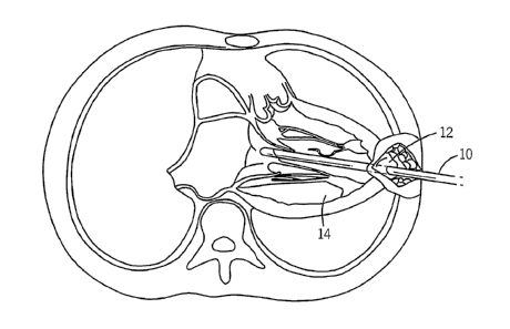
[0014] Under general anesthesia and double-lumen ventilation, the patient
is
prepped and draped so as to allow ample surgical access to the right lateral,
anterior
and left lateral chest wall (from the posterior axillary line on one side to
the posterior
axillary line on the other side). As shown in Fig. 1, one or more
thoracoscopic ports
are inserted in the left chest through the intercostal spaces and an
instrument 10 is
inserted through one of these ports into the chest cavity. Alternatively, a
small (3-5
cm) left thoracotomy is performed in the fifth or sixth intercostals space on
the
anterior axillary line. The patient is fully heparinized. After collapsing the
left lung,
-4-
CA 02595459 2007-07-20
WO 2006/078694
PCT/US2006/001699
the pericardium overlying the apex 12 of the left ventricle 14 is opened and
its edges
are suspended to the skin incision line. This provides close access to the
apex of
the heart. Guidance of the intracardiac procedure is provided by a combination
of
transesophageal or intravascular echocardiography (not shown in the drawings)
and
with direct visualization through a fiber-optical system built into the
instrument 10 as
will be described in detail below. A double-pledgeted purse-string suture is
placed
on the apex of the left ventricle 12 and a stab incision is made at that
location. The
surgical instrument 10 is inserted through this incision, into the left
ventricular
chamber 14 of the beating heart.
[0015] Referring particularly to Fig. 2, the instrument 10 may be used to
grasp
a prolapsing segment of the mitral valve 16 and an artificial chorda 18 may be
secured to its free edge. Accurate positioning of the implanted artificial
chorda 18 is
guaranteed by both echo and direct fiberoptic visualization as will be
described in
detail below. The instrument 10 is then withdrawn from the left ventricle
chamber 14
pulling the unattached end of the neo-implanted chorda 18 with it. Hemostasis
is
achieved by tying the purse-string suture around the incision in the left
ventricular
apex 12 after the instrument 10 and chorda 18 are withdrawn. As shown in Fig.
3,
the neo-implanted chorda 18 is appropriately tensioned under direct echo-
Doppler
visualization and secured outside the apex 12 of the heart. That is, a tension
is
placed on the neo-implanted chorda 18 and the operation of the repaired valve
16 is
observed on the ultrasound image. The tension is adjusted until regurgitation
is
minimized.
[0016] While a single chorda 18 is implanted in the above description,
additional chorda, or sutures, can be implanted and attached to the apex 12 of
the
heart wall with optimal tension. In this case the tensions in all the neo-
implanted
chorda 18 are adjusted until optimal valve operation is achieved.
[0017] As shown in Figs. 4 and 5, the instrument 10 used to perform the
above procedure includes a rigid metal shaft 100 having a handle 120 at its
extrathoracic (proximal) end which enables the instrument to be manipulated
and
guided into position. Actuating mechanisms for controlling the grasping
mechanism
and needle mechanism located at the distal end 140 of the instrument are also
mounted near the handle 120. As will be described below, the grasping
mechanism
-5-
CA 02595459 2007-07-20
WO 2006/078694
PCT/US2006/001699
is operated by squeezing the scissor-grip handle 120, and the needle mechanism
is
operated by moving an up-turned control shaft 122.
[0018] Located on the distal, intracardiac end 140 of the instrument 10
is a
grasping mechanism which can be operated to hold a prolapsing valve leaflet.
As
shown in Figs. 6 and 7, in the preferred embodiment this mechanism is a tip
160
which is supported on the distal end of the shaft 100 by a set of rods 162.
The rods
162 slide within the shaft 100 to move the tip 160 between an open position as
shown in Figs. 6B and 7 and a closed position as shown in Fig. 6A when the
scissor-
grip handle 120 is operated. As will be explained below, a mitral valve
leaflet is
located in the gap between the open tip 160 and the distal end of shaft 100
and it is
captured by closing the tip 160 to pinch the valve leaflet therebetween.
[0019] Disposed in a needle lumen 164 formed in the shaft 100 is a needle
180 which connects to the control shaft 122 at the proximal end of shaft 100.
Needle mechanism 180 slides between a retracted position in which it is housed
in
the lumen 164 near the distal end of the shaft 100 and an extended position in
which
it extends into the sliding tip 160 when the tip is in its closed position. As
a result, if
a valve leaflet has been captured between the tip 160 and the distal end of
shaft 100
the needle may be extended from the lumen 164 by moving control shaft 122 to
puncture the captured leaflet and pass completely through it.
[0020] The distal end of the shaft 100 also contains an artificial
chorda, or
suture 18 that is to be deployed in the patient's heart. The suture 18 is
typically a 4-
0 or 5-0 suture manufactured by a company such as Gore-Tex. This suture 18 is
deployed by the operation of the grasping mechanism and the needle mechanism
180 as described in more detail below.
[0021] The shaft 100 has a size and shape suitable to be inserted into
the
patient's chest and through the left ventricle cardiac wall and form a water-
tight seal
with the heart muscle. It has a circular or ellipsoidal cross-section and it
houses the
control links between the handle end and the intracardiac end of the
instrument as
well as a fiber optic visualization system described in more detail below.
[0022] As shown in Figs. 8A-8F, the preferred embodiment of the suture
deployment system at the distal end of the instrument 10 is positioned around
a
valve leaflet 16 to be repaired as shown in Fig. 8A. The suture 18 is folded
at the
-6-
CA 02595459 2007-07-20
WO 2006/078694
PCT/US2006/001699
middle to form a loop 19 that is positioned in the tip 160. Both ends of the
suture 18
are disposed in a suture lumen 165 formed in the shaft 100 beneath the rods
162.
As shown in Fig. 8B, the valve leaflet 16 is grasped by closing the tip 160,
and the
needle 180 is extended to puncture the leaflet 16 and extend into the tip 160.
A
notch 166 formed on one side of the needle 180 hooks the suture loop 19. The
needle 180 is then retracted back through the leaflet 16 to pull the suture
loop 19
through the puncture opening as shown in Fig. 8C. The leaflet 16 is then
released
and the instrument 10 is withdrawn from the heart as shown in Fig. 8D pulling
both
ends and the midpoint of the suture 18 with it. As shown in Fig. 8E, the
suture 18 is
released by the instrument 10 and the surgeon inserts the two suture ends 21
through the loop 19 at its midpoint. The ends 21 are then pulled and the loop
19
slides along the suture 18 back into the heart chamber 14 where it forms a
Larks
head around the edge of the valve leaflet as shown in Fig. 8F.
[0023] Multiple sutures 18 may be implanted in this manner until a
satisfactory
result is obtained. After deployment of the sutures 18, the heart wall
incision is
repaired by either a pre-positioned purse-string suture or by any kind of
appropriate
hemostatic device or technique. Hemostasis is checked, appropriate chest
drainage
tubes are positioned and secured, and all incisions are closed.
[0024] As shown in Figs. 9A-9D, a second embodiment of the suture
deployment system at the distal end of the instrument 10 is positioned around
a
valve leaflet 16 to be repaired as shown in Fig. 9A. The suture 18 in this
embodiment is a closed loop with one end of the loop disposed in the tip 160
and its
other end disposed in the lumen 164 and wrapped around the needle 180. The
needle 180 is extended through the grasped valve leaflet 16 into the
instrument tip
160 where it hooks one end of the looped suture 18 in a notch 166 formed on
one
side of the needle as shown in Fig. 9B. The needle 180 is then retracted to
pull the
the looped suture 18 through the puncture opening in the leaflet 16. The
leaflet is
then released as shown in Fig. 90 by sliding the tip 160 to its open position.
The
instrument 10 is then withdrawn as shown in Fig. 9D to slide the unhooked end
of
the looped suture 18 along the length of the needle toward the leaflet 16
where it
forms a Larks head around the leaflet edge.
-7-
CA 02595459 2007-07-20
WO 2006/078694
PCT/US2006/001699
[0025] The instrument 10 is then withdrawing from the heart chamber 14
pulling the hooked end of the suture 18 through the heart wall. The suture 18
is
secured to the outside of the heart apex.
[0026] As shown in Figs. 10A-10D, a third embodiment of the suture
deployment system at the distal end of the instrument 10 is positioned around
a
valve leaflet 16 to be repaired as shown in Fig. 10A. The midpoint 17 of the
suture
18 is looped around the lumen 164 and its two loose ends 20 are coiled up in
the tip
160. After the tip 160 is closed to capture the valve leaflet 16, the needle
180 is
extended through the grasped valve leaflet 16 into the instrument tip 160. The
free
ends 20 of the suture 18 are positioned in the tip 160 to form a loop 19 and a
notch
166 formed on one side of the needle extends through this loop 19 and "hooks"
the
free ends of the suture 18 as shown in Fig. 10B. The needle 180 is then
retracted
back into the lumen 164 to pull the hooked ends of the suture 18 through the
puncture opening in the leaflet 16. The leaflet is then released as shown in
Fig. 100
by sliding the tip 160 to its open position. The instrument 10 is then
withdrawn from
the heart as shown in Fig. 10D to pull the free ends 20 back through the valve
leaflet
16 and a Larks head is formed around the leaflet edge by the midpoint 17 of
the
suture 18.
[0027] The instrument 10 is then withdrawn from the heart chamber 14
pulling
the free ends 20 of the suture 18 through the heart wall. The free ends 20 of
the
suture 18 are secured to the outside of the heart apex.
[0028] Other suture deployment systems are possible where, for example,
the
needle may penetrate through the leaflet and link up with a snap fitting
device that is
attached to one end of the looped suture 18 in the instrument tip 160. The
needle
then withdraws pulling the device and looped suture back through the
penetration
opening in the leaflet as described above.
[0029] As shown in Fig. 7 to enhance visibility during this procedure,
four
fiberoptic channels 170 extend along the length of the instrument shaft 100
and
terminate at its distal end. Each channel 170 contains at least one
illuminating fiber
which connects at its extrathoracic end to a white light source (not shown in
the
drawings). Each channel 170 also contains at least one sensor fiber which
conveys
reflected light from the distal end back to a visualization monitor (not shown
in the
-8-
CA 02595459 2007-07-20
WO 2006/078694
PCT/US2006/001699
drawings) connected to its extrathoracic end. In the preferred embodiment each
channel 170 includes two illuminating fibers and two sensor fibers.
[0030] The four fiberoptic channels 170 are disposed around the needle
lumen 164 such that when a valve leaflet 16 is properly grasped, the valve
leaflet
tissue 16 rests against the distal end of all the fibers 170. As a result,
light is
reflected off the tissue back into the sensor fibers and four white circles
are
displayed on the visualization monitor. When the leaflet 16 is not properly
pressed
against the distal end of a channel 170, light is not reflected from the
leaflet 16 and
the visualization monitor displays the red color reflected from blood. When no
valve
tissue is captured, the monitor shows four red dots and when valve tissue is
captured, the dots corresponding to the fiberoptic channels 170 contacting the
tissue
turn white. If the monitor shows all four dots as white, it means that the
valve tissue
capture is optimal. If only the upper two dots turn white and the bottom dots
remain
red, the "bite" on the valve leaflet 16 is too shallow for a proper attachment
of the
suture 18.
[0031] In addition to the fiberoptic visualization system that insures
that a
valve leaflet is properly captured, other real-time visualization systems are
employed
to help guide the instrument 10 to the valve leaflet 16. Preferably a
transesophageal
or intravascular color-Doppler echocardiography system is used for this
purpose. As
explained above, this imaging system is also used to determine the length of
the
neo-implanted artificial chordae in real-time by observing reduction or
disappearance
of regurgitation by transesophageal or intravascular color-Doppler
echocardiography.
-9-