Note: Descriptions are shown in the official language in which they were submitted.
CA 02623718 2008-03-26
WO 2007/047162
PCT/US2006/039169
A GROUND-FAULT CIRCUIT-INTERRUPTER SYSTEM FOR THREE-PHASE
ELECTRICAL POWER SYSTEMS
BACKGROUND
Field of the Invention
The present invention relates generally to Ground-Fault Circuit-Interrupter
(GFCI) systems, and more particularly to a new and improved GFCI system for
alternating current, separately derived, three-phase electrical power systems
wherein
means are provided for continuously monitoring the current balance conditions
on
the main power supply bus supply lines and on each feeder circuit connected
thereto,
and in the event that a fault condition is determined to exist based on
certain
relationships between the sensed currents in the main bus supply lines and the
sensed currents in any feeder circuit, then the faulted circuit will be
tripped and the
other circuits will be inhibited from tripping.
Discussion of the Prior Art
Prior art ground-fault protective systems are intended to sense small
differences in current in power conductors that normally carry balanced
currents.
Such differences may be caused by leakages of current from one of the line
conductors to ground, thus depriving the neutral conductor of some of the
normal
current that would establish a balance, or zero difference, in current in the
conductors at a sensor. If the differential currents are below certain
predetermined
levels, power is normally allowed to flow uninterrupted. However, if
differential
currents should occur that exceed a predetermined threshold for a long enough
time,
the circuit is interrupted, since it is then probable that an incipient
failure of
insulation or perhaps even a serious shock to a human being is occurring.
Spurious signals often cause ground-fault interrupters to be confused with
real fault currents. For example, power line transients caused by sudden load
changes, or lightning induced surges, can give rise to unnecessary line
tripping in
CA 02623718 2008-03-26
WO 2007/047162 PCT/US2006/039169
ground-fault interrupter systems. Since such disconnections of the circuits
interfere
with efficient system operation, it is not unusual to find that intolerance
thereto has
caused the users of such equipment to establish sensitivity specifications at
dangerously high levels. A steady-state spurious signal frequently experienced
in
three-phase electrical power systems is a capacitive current to ground from at
least
one of several downstream feeder lines. This can be caused by a long cable to
a load,
or by discrete phase-to-ground connected capacitors such as those used to
avoid
damage to load-utilization equipment by power system voltage surges, or by
similar
circuit influences having nothing to do with a true fault on the line. It can
thus be
said that interruptions of the circuit brought about by a ground-fault
detector and
interrupter system for causes that prove to be insufficient, yet cause the
system to
respond by needlessly breaking the circuit without the occurrence of a true
fault, are
a nuisance and must be avoided. A true ground-fault can have different causes
and
can give rise to different levels of current imbalance in the supply
conductors. If the
current imbalance is comparatively high; that is to say, if a comparatively
large
ground-fault current flows, the system should respond quickly and decisively.
Modern GFCI technology has limited application for systems operating
above 125 volts line-to-ground or 250 volts line-to-line. Conventional GFCI
applications are principally applied to single-phase, 120-240 volt power
systems.
When the system is a three-phase, multiple feeder circuit system operating
above
125 volts-to-ground (e.g., systems rated 400 or 480 volts phase-to-phase,
which
have a normal voltage-to-ground of 230 and 277 volts, respectively), and one
phase
is faulted to ground, the magnitude of the capacitive charging currents on the
unfaulted phases of the non-affected feeders can easily reach a magnitude that
will
"false trip" the non-affected feeders' GFCIs. This is not a common problem on
systems rated below 125 volts to ground (e.g., a 240-120 volt single-phase
system or
a 208Y/120 volt three-phase system), because it takes an exceptionally long
feeder
circuit (with a circuit conductor length of approximately 1000 feet) to result
in a
capacitive charging current above the GFCI trip level of 4 to 6 mA.
A common voltage used for lighting circuits in the United States is 277 volts
phase-to-ground (or phase-to-neutral), which is the voltage to ground or
neutral that
exists for all three-phase electrical systems rated 480 volts phase-to-phase
(except
-2-
CA 02623718 2008-03-26
WO 2007/047162 PCT/US2006/039169
unusual "corner grounded" systems). In a typical situation involving possible
electrocution of an individual completing a ground-fault circuit through his
body,
death does not occur instantaneously, but results most often from ventricular
fibrillation. The higher the electrocuting current, the shorter the time in
which
ventricular fibrillation occurs. Using the 95th percentile human body
resistance at
1000 volts (reference IEC TS 60479-1, Fourth Edition, July 2005) yields a
"dry"
hand-to-hand resistance of 1050 ohms and a dry hand-to-foot resistance of 945
ohms. As an example, the lowest resistance, a dry hand-to-foot resistance of
945
ohms, can be used in a sample calculation for a 690 volt system. At a lower
voltage
of 225 volts, the dry hand-to-hand resistance is 1900 ohms and the dry hand-to-
foot
resistance is approximately 1710 ohms. Using these resistances, a hand-to-hand
resistance is 1900 ohms corresponds to a body current flow of 146 milliamperes
(mA) at a voltage of 277 volts. The hand-to-foot resistance of 1710 ohms
corresponds to a body current flow of 162 mA at a voltage of 277 volts. Either
of
these illustrated levels of current flow are significantly above the threshold
of 6 mA
where a person can voluntarily "let go" of, or rele(ase, a grasped energized
conductor. In fact, these magnitudes of current can result in ventricular
fibrillation of
the heart if the current flow persists through the body for more than
approximately
one second. In fact, many of the electrocution deaths experienced today are at
the
277 volt level.
Ventricular fibrillation is thus considered to be the main mechanism of death
in fatal electrical accidents. Ventricular fibrillation results from shock
currents
through the heart in excess of approximately 40 mA. A published (IEC TS 60479-
1,
Fourth Edition, July 2005, Figure 20) time-current plot for various time
duration
exposures of current flow though the body (for current flow ranging from
approximately 40 mA to 1500 mA), depicts a set of probability curves (ranging
from
a "threshold risk" up to 50% probability) for experiencing ventricular
fibrillation. As
suggested above, the duration of the shock is a key factor. According to IEC
TS
60479-1, "For shock durations below 0.1 s, fibrillation may occur for current
magnitudes above 500 mA, and is likely to occur for current magnitudes in the
order
of several amperes only if the shock falls within the vulnerable period. For
shocks of
such intensities and durations longer than one cardiac cycle, reversible
cardiac arrest
-3-
CA 02623718 2008-03-26
WO 2007/047162 PCT/US2006/039169
may be caused." Additionally, "The vulnerable period occurs during the first
part of
the T-wave in the electrocardiogram, which is approximately 10% of the cardiac
cycle..." A shock will not necessarily result in an electrocution for body
currents of
up to several amperes if the voltage source is removed quickly enough. The
faster
the voltage source is removed from a person, the less likely ventricular
fibrillation
will occur. Ventricular fibrillation often leads to death unless prompt
medical
intervention is initiated (i.e., CPR, followed by defibrillation)
The International Electrotechnical Commission (IEC) "CI" empirical curve
for the threshold 5% probability of ventricular fibrillation for a left-hand-
to-foot
shock (heart current factor of 1.0) can be expressed by the equation:
t(I) = 0.2[(500 - I) / (I - 40)] 0.5
where:
It=ctuimrreenint isnecond,
milliamperes
(nA)
Calculations pursuant to this equation indicate that a GFCI device must clear
400 mA of current within 0.1 second to avoid ventricular fibrillation for the
"worst
case" of a shock from the left hand to a foot.
For a 690 volt three-phase system (maximum voltage of 720 volts phase-to-
phase):
I body = (720/1.732) /945
= 0.440 A, or ¨ 440 mA
One fact that has inhibited the application of GFCIs on voltages greater than
125 volts line-to-ground, or on three-phase systems, is that, as pointed out
above, all
feeder circuit conductors on such power systems have a characteristic
capacitance-
-4-
CA 02623718 2008-03-26
WO 2007/047162
PCT/US2006/039169
to-ground. This is referred to as "system charging current" and is described
below.
The normal system charging current present on all such systems can often
exceed
the nominal 6 mA threshold of GFCI devices and result in the nuisance tripping
of
GFCI protected circuits that are not actually involved in the circuit that has
a
ground-fault.
Referring now to Fig.1 of the drawing, a three-phase source S is shown
coupled via main phase lines A, B, C to a pair of loads LOAD1 and LOAD2
through feeder lines A', B', C' and A", B" C", respectively. This circuit
represents a
Prior Art GFCI application in which separate multiple GFCI units, such as the
depicted units GFSI1 and GFSI2, are used as protective mechanisms in the
respective feeder circuits. Shown in dashed lines are capacitive symbols "Co"
representing the distributed capacitances-to-ground for each feeder line. The
system
charging current "Ic" for the feeder circuit to LOAD1 can be calculated from
the
per-phase capacitance-to-ground values using the following equations:
Ic = 3 Ico = 'OWL / )(co
Xeo = (106) / 27rfCõ
where
Ic = System charging current during a ground-fault, in amperes;
Ico = System charging current of each phase during normal system
conditions (no ground-fault), in amperes [Icoi;
VLL = System line-to-line voltage, in volts;
Xco = Per-phase capacitive reactance, in ohms [Xcoi;
f = Frequency, in Hertz; and
Co = Per-phase capacitance-to-ground, in microfarads.
-5-
CA 02623718 2008-03-26
WO 2007/047162 PCT/US2006/039169
Using the above equations for a 13 mA system charging current (Ic) at 480
volts (typical for a three-conductor insulated cable circuit in metallic
conduit of a
1000 ft length) yields:
Xec, 1.732(480) / 0.013
--- 64,000 ohms per phase for a 1000 ft long feeder cable
From the prior calculation of "body resistance," it will be apparent that when
a person touches an energized electrical phase conductor, it is equivalent to
putting a
resistor in the order of 1050 ohms in parallel with a -j64,000 ohm capacitive
reactance Xco, except that the capacitance is distributed along the entire
cable
leading to the source, and most of the current will take the more direct path
through
the body resistance. (Note: RN in Fig. 1 is the system's neutral grounding
resistor and
can vary from zero resistance for a solidly-grounded system, to a few hundred
ohms
for a high-resistance grounded system, to an infinite value for an ungrounded
system.
In the illustrated example, a fault in any of the feeder lines to LOAD1 will
be
sensed by GFCI 1. Note that as depicted, GFCI1 includes a circuit breaker CB1
and a
ground-fault sensor detection device GFS1 that is coupled to an overall core-
balance, current transformer CT1 that encircles all three phases A', B' and C'
(as well
as the neutral for a three-phase, four-wire system if used). Each of the
capacitive
charging currents in the three-phase load conductors (and neutral) sum to zero
for a
balanced or unbalanced load condition. Under normal system operating
conditions,
the capacitive charging currents Ico in all three phases are equal and sum to
zero.
In this example, the fault current induced on the multi-turn secondary
winding W1 of CT1 is proportional to the vectorial sum of the capacitive
charging
currents flowing in the three line conductors A', B', C'. As long as this sum
is below
a predetermined threshold value (typically 4 to 6 mA), the net flux induced in
the
core of CT1 and correspondingly, the fault current induced on its multi-turn
secondary winding W1 and coupled into GFS1 will be beneath the trip threshold
thereof.
-6-
CA 02623718 2008-03-26
WO 2007/047162 PCT/US2006/039169
In the absence of an induced fault current in winding W1 exceeding the
threshold level, the differential current transformer remains correspondingly
"balanced", and circuit breaker CB1 is held in its closed state. However,
should a
fault to ground occur, such as is shown at "F" in Fig. 1, where line A' is
shorted to
ground, the vectorial sum of the capacitive charging currents in lines A', B',
C' will
no longer be less than the threshold value, and the corresponding fault
current
induced in the seCondary winding W1 will cause the differential transformer of
GFS1 to become unbalanced, and trip circuit breaker CB1 to interrupt the
feeder
circuit to LOAD1 and clear the ground-fault F.
But in addition, as may be further noted in Fig. 1, and as will be further
discussed below, during the fault, the unbalanced voltages that exist with
respect to
ground also force current flow (currents Ib2 and 1.2) in phases B" and C" of
the
feeder circuit to LOAD2 (and any other feeder circuits in the system driven by
source S). These two currents can result in a false trip of the non-faulted
feeder
circuit if the resulting unbalance causes the generation of a fault current in
W2 that
exceeds the trip threshold of GFS2: This of course causes an unnecessary
"nuisance"
trip and should be avoided.
There is thus a need for a GFC1 system for three-phase applications
principally operating at voltages above 125 volts and having a ground-fault
pickup
sensitivity of 4 to 6 mA (corresponding to the lower limit of the human "let-
go"
threshold of current), and which will trip within several seconds of a ground-
fault in
excess of a current level of 6 mA, or within 0.025 to 0.100 second for ground-
fault
current in excess of 20 mA to 30 mA.
Furthermore, there is a need for a GFCI system that will quickly determine
which line has been faulted and will interrupt the feeder circuit including
that line
without interfering with the operation of other feeder circuits in the system.
In addition to the advantages of the GFCI system described above to avoid
fatal shocks, incipient failure of electrical insulation can also be detected
at a current
sensitivity of 6 to 30 mA, which can minimize equipment damage.
SUMMARY
-7-
CA 02623718 2008-03-26
WO 2007/047162 PCT/US2006/039169
It is therefore an object of the present invention to provide an improved
ground-fault circuit-interrupter system capable of quickly detecting and
eliminating
a system fault without causing nuisance interruptions to non-faulted circuits
of the
monitored power supply system.
Another objective of the present invention is to provide a means to
compensate for the small capacitive currents that flow throughout a three-
phase
power system during a low-or high-level ground-fault and to thereby avoid
nuisance
tripping of the non-faulted circuits. '
Still another objective of the present invention is to provide a GFCI system
for three-phase power supply systems which makes an immediate determination of
where within the system the fault resides and causes immediate interruption of
the
faulted lines while inhibiting interruption of other lines within the system.
Briefly, a presently preferred embodiment of the present invention includes a
plurality of GFCI units and a controller forming a ground-fault circuit
interrupting
system for use in a three-phase power distribution network including a three-
phase
source of electrical power, a three- or four-wire main circuit and a plurality
of three-
or four-wire feeder circuits connected across the main circuit. A GFCI unit is
provided in the main circuit and in each of the feeder circuits. The
controller
continuously monitors the main GFCI unit and each feeder GFCI unit to
determine
when and where a fault has occurred and, in. response thereto, interrupts the
faulted
circuit and inhibits tripping of the non¨faulted circuits. The novel GFCI
system is
applicable for solidly-grounded, resistance-grounded, or ungrounded as well as
other
three-phase systems.
An important advantage of the present invention is that it provides a GFCI
system that can immediately disconnect power from a faulted feeder circuit
without
causing the interruption of the other "healthy" feeder circuits.
Another advantage of the present invention is that it provides a GFCI system
that can immediately detect a fault, determine the source of the fault,
interrupt the
faulted circuit and prevent the interruption of any non-faulted circuits.
-8-
CA 02623718 2008-03-26
WO 2007/047162
PCT/US2006/039169
These and other objects and advantages of the present invention will no
doubt become apparent to those skilled in the art after reading the following
detailed description which makes reference to the several figures of the
drawing.
IN THE DRAWING
Fig.1 is a schematic circuit diagram illustrating a prior art three-phase
circuit
having a GFCI unit;
Fig. la is a one-line diagram of the V-Harm simulation and the assumed
parameters for the system used to develop the Tables shown in the text hereof:
Fig. 2 is a schematic circuit diagram illustrating a three-phase power supply
circuit having multiple feeder circuits and a GFCI system in accordance with a
preferred embodiment of the present invention;
Figs. 3a - 3b are diagrams illustrating the current distributions of a
"solidly
grounded" system;
1 5 Figs. 4a - 4b are diagrams illustrating the current distributions of a
"high-
resistance grounded" system;
Figs. 5a - 5b are diagrams illustrating the current distributions of an
"ungrounded" system;
Fig. 6 is a flow chart illustrating operation of the processor of Fig. 2 in
the
case of an ungrounded power system;
Fig. 7 is a flow chart illustrating operation of the processor of Fig. 2 in
the
case of a solidly-grounded or high-resistance power system; and
Fig. 8 is a block diagram representation of the fundamental components of
one (of multiple) feeder circuit of a GFCI system in accordance with a
preferred
embodiment of the present invention.
DETAILED DESCRIPTION
-9-
CA 02623718 2008-03-26
WO 2007/047162 PCT/US2006/039169
A premise upon which the present invention is based is that, while workers
should always exercise safe work practices, i.e., by de-energizing and
"locking out"
the circuit to be worked on, and "testing before touching" the circuit in
order to
avoid the shock hazard, a mistake or oversight should not result in a
fatality.
However, OSHA accident reports documenting dozens of 277 volt fatalities
dating
back to 1990 indicate that inadvertent contact with energized parts has
happened far
too often on the higher voltage systems.
In the case of an accidental fault in a 480Y/277 volt system, the shock
current though a person's body to ground can be calculated to be in the range
of 220
mA to 400 mA. For example, using the "50% of the population" hand-to-hand body
impedance at 400 volts listed on Table 1 of IEC TS 60479-1, the current will
be 277
volts / 950 ohms = 0.29 amperes, or 290 mA. As discussed above, the probable
reason there are so many fatalities involving the 480 volt systems (277 volts
to
ground) is that a person cannot voluntarily let go when he or she grasps an
exposed
live wire or other "energized" part. This is a serious consequence since in
order to
avoid ventricular fibrillation of the heart, the source of shock voltage must
be
removed from the person within approximately 0.3 to 0.6 second of the shock
initiation for a shock current magnitude of 290 mA..
The thesis of the present invention is that among several feeder circuits
sharing a single three-phase power source, the circuit experiencing the
highest
detectable ground-fault current will be the faulted circuit. It is envisioned
that
determination of which circuit has the highest magnitude of sensed ground-
fault
current (above the trip threshold) can be determined by continuously
monitoring the
GFCI units respectively associated with the main circuit and the several
feeder
circuits and determining which unit has the highest ground-fault current. A
computer
simulation of various ground-fault scenarios has confirmed this theory.
More specifically, a computer program called "V-Harm" was used to
simulate and predict the performance of the ground-fault system for various
scenarios. V-Harm is a load flow computer program that represents each phase
of
the three-phase system separately, and calculates the system currents for
unbalanced
load or fault conditions, such as faults from phase to ground. Fig. la depicts
a one-
-10-
CA 02623718 2008-03-26
WO 2007/047162 PCT/US2006/039169
line diagram of the V-Harm simulation and the assumed parameters for the
system
used to develop the Tables shown below.
Three representative types of three-phase power systems were simulated,
solidly- grounded, high-resistance grounded, and ungrounded. Three degrees of
fault
resistance were simulated for each type of system: zero ohms to represent the
extreme of a solid "bolted" fault, 700 ohms to represent the average
resistance of a
person's body at the 480-volt system voltage, and 46,000 ohms to represent the
6
mA protective threshold current level at 277 volts-to-ground.
-11-
CA 02623718 2008-03-26
WO 2007/047162
PCT/US2006/039169
DATA
= Frequency = 60 Hz
= Source Impedance at 13,8 kV = 0 Ohms
= Transformer
600 kVA
13.8 kV/480V
Delta/Wye (The grounding at the wye is vaned in the analysis.)
X = 5/5%
R = 1.44%
= 480V Feeder (These parameters are estimated based on a three-phase, three-
wire system with 2/0 copper conductors in steel conduit. There is no neutral
except
for the Series III cases. A 2/0 copper equipment grounding conductor Is run
with all
the feeder circuits.)
Zi = 0.1020 + j0.0533 ohms/100V
Z, = 0.3214 + j0.1002 ohms/1000'
Ci = 70 01000'
= 40 nf/1000'
= Loads (The loads are connected in an ungrounded- wye configuration for
the
Series f & II cases. In the Series Ill cases, the neutral of each load is
connected to
its neutral conductor.)
- Series I & II
Feeder 1 ¨ balanced three-phase 90 kW, 0,9 pf
Feeder 2 ¨ balanced three-phase 90 kW, 0.9 of
Feeder 3¨ balanced three-phase 90 kW, 0.9 pf
Feeder 4¨ balanced three-phase 90 kW, 0,9 pf
with a 1.0 uf surge capacitor connected
from each phase-to-ground
- Series Ill
Feeder 1 ¨ Phase A-N ¨ 30 kW, 0.90 pf
Phase B-N ¨ 20 kW, 0,85 pf
Phase C-N ¨ 10 kW, 0.80 pf
Feeder 2¨ Phase A-N ¨ 15 kW, 0.90 pf
Phase B-N ¨ 35 kW, 0.85 pf
Phase C-N ¨ 25 kW, 0.80 pf
Feeder 3 ¨ Phase A-N 20 kW, 0.90 pf
Phase B-N ¨ 20 kW, 0.85 pf
Phase C-N ¨30 kW, 0.80 pf
Feeder 4¨ Is Disconnected
Examining Tables 1 and 4 (for a solidly grounded system) and Tables 2 and
(for a high- resistance grounded system), it can be concluded that in every
case
5 that a ground-fault does not involve the main bus, the faulted feeder
is the one that
has the highest sensed ground-fault current.
-12-
CA 02623718 2008-03-26
WO 2007/047162 PCT/US2006/039169
Tables 3 and 6 (for an ungrounded system) illustrate that the faulted feeder
always has the highest sensed ground-fault current, but the discrimination
between
some of the other feeders (depending on the particular feeder's charging
capacitance
and the resistance or impedance of the ground-fault itself) is not as great as
with the
solidly- and resistance- grounded systems.
Table 7 illustrates that unbalanced phase-to-neutral loads have no affect on
the sensed ground-fault currents, if the sensor current transformer encloses
the phase
and neutral conductors.
-13-
CA 02623718 2008-03-26
WO 2007/047162
PCT/US2006/039169
TABLE 1 ¨ ("Series I" Case ¨ system with load on feeders)
Summary Table of Fault Current (shaded blocks) and Current Distribution ¨
= Solidly Grounded 480 Volt System;
= Ground-Fault at "Far End" of Feeders
= 90 kW Ungrounded Balanced Load on All Feeders
= Feeder 4 with 1.0 ttF Surge Capacitor Connected on Far End to
Ground
(Current in milliamperes as sensed by a core-balance or differential
current transformer, unless shown otherwise)
Main Fdr 1 Fdr 2 Fdr 3 Fdr
4
Phase-Ground Fault onMain Bus
700 ohm ground fault 375 375 0 0 0 -
46,000 ohm ground fault 6 1 0 1
Phase-Ground Fault on Feeder 3
46,000 ohm ground fault 5 0 0 0
Phase-Ground Fault on Feeder 4
Note: Underlined currents on the non-faulted circuits represent a sensed
current at or above a 5 mA protective threshold level.
-14-
CA 02623718 2008-03-26
WO 2007/047162 PCT/US2006/039169
TABLE 2 ¨ ("Series I" Case ¨ system with load on feeders)
Summary Table of Fault Current (shaded blocks) and Current Distribution ¨
= High-Resistance Grounded 480 Volt System;
= Ground-Fault at "Far End" of Feeders;
= 90 kW Ungrounded Balanced Load on All Feeders;
= Feeder 4 with 1.0 pf` Surge Capacitor Connected on Far End to
Ground
(Current in milliamperes as sensed by a core-balance or differential
current transformer, unless shown otherwise)
Main Fdr 1 Fdr 2 Fdr 3 Fdr 4
Phase-Ground Fault on Main Bus
Solid ground fault 1981 6 12 24 311
700 ohm ground fault 323 1 2 4 50
46,000 ohm ground fault 6 ' I 0 0 2
Phase-Ground Fault on Feeder 1
Solid ground fault 1899 1931 11 24 303
700 ohm ground fault 309 315 2 4 50
46,000 ohm ground fault 6 0 0 1
Phase-Ground Fault on Feeder 2
Solid ground fault 1854 6 1882 23 295
700 ohm ground fault 302 2 307 3 48
46,000 ohm ground fault 6 0 0 1
Phase-Ground Fault on Feeder 3
Solid ground fault - 1770 6 11 1795 282
700 ohm ground fault - 288 1 2 293 47
46,000 ohm ground fault 5 0 0
Phase-Ground Fault on Feeder 4
Solid ground fault 1901 6 11 - 24 1903
700 ohm ground fault - 308 1 2 4 309
46,000 ohm ground fault 4
Note: Underlined currents on the non-faulted circuits represent a sensed
current at or above a 5 mA protective threshold level.
-15-
CA 02623718 2008-03-26
WO 2007/047162
PCT/US2006/039169
TABLE 4 ¨ ("Series II" Case ¨ system with no load on feeders)
Summary Table of Fault Current (shaded blocks) and Current
Distribution ¨
= Solidly Grounded 480 Volt System;
= Ground-Fault at "Far End" of Feeders;
= No Load on All Feeders;
= Feeder 4 with 1.0 uf Surge Capacitor Connected on Far End to
Ground
(Current in milliamperes as sensed by a core-balance or differential
current transformer, unless shown otherwise)
Main Fdr 1 Fdr 2 Fdr 3 Fdr 4
Phase-Ground Fault on Main Bus
Solid ground fault 10 kA 3 4 9 109
700 ohm ground fault 396 0 0 0 1
=
46,000 ohm ground fault 6 1 0 0 1
Phase-Ground Fault on Feeder 1
Solid ground fault 2.4 kA 2.4 kA 1 2 26
700 ohm ground fault 393 396 0 0 1
46,000 ohm ground fault 6 6 0 0 0
Phase-Ground Fault on Feeder 2
Solid ground fault 1.3 kA 1 1.3 kA 1 14
700 ohm ground fault 396 0 396 0 0
46,000 ohm ground fault 6 0 6 0 1
Phase-Ground Fault on Feeder 3
Solid ground fault 0.70 kA 1 1 0.70 kA 8
700 ohm ground fault 395 0 0 396 0
46,000 ohm ground fault 6 1 0 6 1
- Phase-Ground Fault on Feeder 4
Solid ground fault 2.4 kA 1 1 2 2.4 kA
-17-
CA 02623718 2008-03-26
WO 2007/047162 PCT/US2006/039169
TABLE 3 ¨ ("Series 1" Case ¨ system with load on feeders)
Summary Table of Fault Current (shaded blocks) and Current
Distribution ¨
= Ungrounded 480 Volt System;
= Ground-Fault at "Far End" of Feeders;
= 90 kW Ungrounded Load On All Feeders;
= Feeder 4 with 1.0 ILLF Surge Capacitor Connected on Far End to
Ground
(Current in milliamperes as sensed by a core-balance or differential
current transformer, unless shown otherwise)
Main Fdrl Fdr 2 Fdr 3 Fdr 4
Phase-Ground Fault on Main Bus
Solid ground fault - 359 6 11 24
310
700 ohm ground fault 263 5 8 18 227
-
46,000 ohm ground fault 6 , 0 0 0 5
Phase-Ground Fault on Feeder 1
Solid ground fault 2 345 11 24 304
700 ohm ground fault 2 252 8 18 223
46,000 ohm ground fault 1 5 0 0 5
Phase-Ground Fault on Feeder 2 -
Solid ground fault 1 6 ,332 24 296
700 ohm ground fault 2 5 242 17 217
46,000 ohm ground fault 1 0 0 5
Phase-Ground Fault on Feeder 3
Solid ground fault 1 5 10 303 283
700 ohm ground fault 1 4 8 222 206
46,000 ohm ground fault 0 0 0 5 3
Phase-Ground Fault on Feeder 4
Solid ground fault I6 11 24 46
700 ohm ground fault 0 5 9 17 34
46,000 ohm ground fault 1 0 1 0 2
Note: Underlined currents on the non-faulted circuits represent a sensed
current at or above a 5 mA protective threshold level.
-16-
CA 02623718 2008-03-26
WO 2007/047162
PCT/US2006/039169
700 ohm ground fault 396 1 0 0 396
46,000 ohm ground fault 7 1 0 0 6
Note: Underlined currents on the non-faulted circuits represent a sensed
current at or above a 5 mA protective threshold level.
-18-
CA 02623718 2008-03-26
WO 2007/047162 PCT/US2006/039169
TABLE 5 ¨ ("Series II" Case ¨ system with no load on feeders)
Summary Table of Fault Current (shaded blocks) and Current
Distribution ¨
= High-Resistance Grounded 480 Volt System;
= Ground-Fault at "Far End" of Feeders;
= No Load on All Feeders;
= Feeder 4 with 1.0 !IF Surge Capacitor Connected on Far End to
Ground
(Current in milliamperes as sensed by a core-balance or differential
current transformer, unless shown otherwise)
Main Fdr 1 Fdr 2 Fdr 3 Fdr 4
Phase-Ground Fault on Main Bus
Solid ground fault 2035 7 12 25 320
700 ohm ground fault 332 2 2 4 52
46,000 ohm ground fault 6 1 0 0 1
Phase-Ground Fault on Feeder 1
Solid ground fault 2001 2038 12 25 319
700 ohm ground fault 326 332 2 4 " 51
46,000 ohm ground fault 7 7 0 0 1
Phase-Ground Fault on Feeder 2
Solid ground fault 2005 7 2032 25 319
700 ohm ground fault 328 2 332 4 52
46,000 ohm ground fault 6 0 6 0 1
Phase-Ground Fault on Feeder 3
Solid ground fault 2002 7 12 2027 319
700 ohm ground fault 328 2 2 331 52
46,000 ohm ground fault 7 1 0 61
Phase-Ground Fault on Feeder 4
Solid ground fault 2005 7 12 25 2005
700 ohm ground fault 326 1 2 4 327
46,000 ohm ground fault 7 0 0 0
Note: Underlined currents on the non-faulted circuits represent a sensed
current at or above a 5 mA protective threshold level.
-19-
CA 02623718 2008-03-26
WO 2007/047162 PCT/US2006/039169
TABLE 6 ¨ ("Series II" Case ¨ system with no load on feeders)
Summary Table of Fault Current (shaded blocks) and Current
Distribution ¨
= Ungrounded 480 Volt System;
= Ground-Fault at "Far End" of Feeders;
= No Load on All Feeders;
= Feeder 4 with 1.0 pF Surge Capacitor Connected on Far End to
Ground
(Current in milliamperes as sensed by a core-balance or differential
current transformer, unless shown otherwise)
Main Fdr 1 Fdr 2 Fdr 3 Fdr 4
Phase-Ground Fault on Main Bus
Solid ground fault 366 8 12 25 320
700 ohm ground fault 270 5 9 J. 236
46,000 ohm ground fault 6 - 1 0 1 7 -
Phase-Ground Fault on Feeder 1
____________________________________________________________________________ _
Solid ground fault 3 362 12 25 320
700 ohm ground fault 1 265 9 19 - 234
46,000 ohm ground fault 1 7 , 0 1 5
_ ___________________________________________________________________________
Phase-Ground Fault on Feeder 2
Solid ground fault 1 7 354 25 319
700 ohm ground fault 1 5 261 , 19 237
46,000 ohm ground fault 1 0 6 1 6
Phase-Ground Fault on Feeder 3
Solid ground fault 1 7 12 341 320
700 ohm ground fault 2 5 9 ' 252 237
46,000 ohm ground fault 1 0 0 6
Phase-Ground Fault on Feeder 4
Solid ground fault 1 7 12 25
700 ohm ground fault 1 4 9 19 ' 34
46,000 ohm ground fault 1 0 0 1
Note: Underlined currents on the non-faulted circuits represent a sensed
current at or above a 5 mA protective threshold level.
-20-
CA 02623718 2008-03-26
WO 2007/047162
PCT/US2006/039169
TABLE 7¨ ("Series III" Case ¨ system with unbalanced phase-neutral
load on feeders)
Summary Table of Fault Current (shaded blocks) and Current Distribution ¨
= Solidly Grounded 480 Volt System;
= Ground-Fault at "Far End" of Feeders;
= Unbalanced Phase-to-Neutral Load on All Feeders;
= Feeder 4 Disconnected
(Current in milliamperes as sensed by a core-balance or differential
current transformer enclosing phase and neutral conductors, unless shown
otherwise)
Main Fdr 1 Fdr 2 Fdr 3 Fdr 4
Phase-Ground Fault on Main Bus
Solid ground fault 1O kA, 3 4 8
700 ohm ground fault ' 389 0 1 1
46,000 ohm ground fault 6 0 1 1
Phase-Ground Fault on Feeder 1
Solid ground fault 2.5 kA 2.5kA 1 2
700 ohm ground fault 380 378 1 1 -
46,000 ohm ground fault 6 6 1 0
Phase-Ground Fault on Feeder 2
Solid ground fault 1.4 kA 1 1.4 kA 1
700 ohm ground fault 387 0 385 0
46,000 ohm ground fault 7 0 6. 0
Phase-Ground Fault on Feeder 3
Solid grOund fault 0.75 kA 1 1 0.75 kA -
700 ohm ground fault 369 1 1 366 -
46,000 ohm ground fault 7 0
Phase-Ground Fault on Feeder 4
Solid ground fault
700 ohm ground fault - ,
46,000 ohm ground fault -
Note: Underlined currents on the non-faulted circuits represent a sensed
current at or above a 5 mA protective threshold level.
-21-
CA 02623718 2008-03-26
WO 2007/047162 PCT/US2006/039169
It is thus clear that the computer simulations validate the concept of the
present invention.
It is envisioned that such fault determination can be made within
approximately 0.010 second of the fault initiation (i.e., by sensing and
determining
the peak of all sensor current inputs within +/- 0.005 sec of the first peak
current that
is above the current pickup threshold). Furthermore, electrical isolation
(circuit
interruption) can be accomplished within 0.025 to 0.050 second of fault
initiation for
typical low-voltage applications, and within 0.10 second (to allow for the
slower
operation of normal circuit breakers) for applications of this technology on
systems
rated above 1000 volts phase-to-phase.
The concept is simple - even though the sensed currents in multiple feeder
circuits may be above the 4 to 6 mA trip level, the three-phase feeder circuit
that has
the current of greatest magnitude is the circuit that has the ground-fault and
is the
only circuit that needs to be tripped and isolated.
A more comprehensive application of this idea is an interlocked GFCI
sensing system that would involve several protection levels within a
separately-
derived three-phase system. For example, a GFCI system that could be applied
on
main low-voltage switchgear and downstream panel boards, or motor control
centers
and still accomplish the discrimination, sensitivity, and speed necessary to
prevent
electrocution at all levels.
The basic concept implemented by the present invention is the provision of
means to (1) continuously monitor the small capacitive currents that flow
throughout
a three-phase power system during a low-level or high-level ground-fault
(i.e., at one
extreme, a fault through a person's relatively high body resistance, or at the
other
extreme, a low-resistance, solid metallic fault from a phase conductor to
ground), (2)
determine the source of the fault, and (3) simultaneously react to (a)
interrupt the
faulted source or feeder line, and (b) inhibit the tripping of other non-
faulted feeder
circuits.
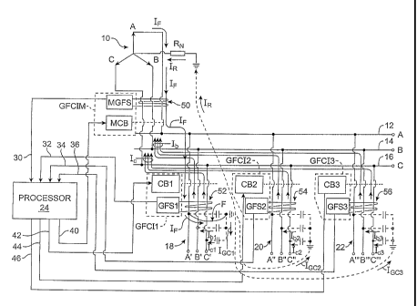
In Fig. 2 of the drawing, a schematic circuit diagram is shown generally
illustrating a three-phase, separately derived power supply circuit 10 coupled
(by a
-22-
CA 02623718 2008-03-26
WO 2007/047162 PCT/US2006/039169
main panel or switchable bus, not shown) to three power lines 12, 14, and 16
providing three power phase circuits A, B and C. Connected to the lines 12,
14, and
16 are three feeder circuits shown at 18, 20, and 22 ,respectively including
three
power lines A', B' and C'; A", B" and C"; and A', B" and C".
Also depicted in Fig. 2 is a GFCI system in accordance with the present
invention. The system includes a GFCI unit designated GFCIM in the main
circuit,
and units GFCI1, GFCI2 and GFCI3 the feeder circuits 18, 20, and 22,
respectively.
Each GFCI unit includes a ground-fault sensor (GFS1', GFS2 and GFS3,
respectively), as does the main supply (MGFS), and circuit breakers for each
feeder
circuit (designated CBI, CB2 and CB3, respectively) as well as a main supply
breaker MCB.
The system further includes a system processor shown at 24 having inputs
30, 32, 34 and 36, respectively connected to the main sensor MGFS and the
feeder
sensors GFS1, GFS2, and GFS3 and respectively connected to the main circuit
breaker MCB and the several feeder line breakers CB1, CB2 and CB3. These
sensor
inputs and outputs are wired to, or otherwise connected by means such as fiber-
optic
communications, etc., into the central processing device 24 which determines
the
magnitudes of currents (fault signals) detected by the respective sensors, and
either
actuates or inhibits the associated circuit breakers' trip units. The current
magnitudes
or fault signals used in the determination can be the peak, average, or root-
mean-
square measured currents. The fault signals could be digitally processed (or
filtered
using analog means, such as passive filters) and be represented as a
fundamental
power-frequency component only (i.e., 60 or 50 Hz) in order to improve
discrimination of fault current flow from electrical "noise" or harmonic
currents on
the power system.
The main circuit breaker MCB and each feeder circuit breaker (CB1, CB2
and CB3) of this separately-derived three-phase system has an associated
ground-
fault sensor (GFS1, GFS2 and GFS3) implemented as a core balance sensor
(current
transformer) schematically depicted at 50, 52, 54 and 56 respectively, that
encloses
the associated three-phase conductors (and neutral conductor, if applicable).
Each
three-pole feeder circuit breaker includes a shunt-trip device to facilitate
rapid
-23-
CA 02623718 2008-03-26
WO 2007/047162 PCT/US2006/039169
tripping of the circuit. The sensors and breakers could be separate or formed
as
integrated GFCI circuit breaker units.
A periodic "self-test" feature can also be incorporated into the subject GFCI
system to assure that the sensing and tripping circuits are always functional.
A
suitable indicator or an alarm can also be included and initiated when the
GFCI
system has a defect.
When the threshold trip level is exceeded (4 to 6 mA) in any sensor, the
processor 24 determines which GFCI unit has the highest magnitude of sensed
current and identifies it as the main or feeder that has the ground-fault and
must be
tripped (through trip output 40, 42, 44, or 46). The tripping of all other
feeders will
simultaneously be blocked or inhibited so as to avoid nuisance trips.
Feeders other than a faulted feeder may also have a sensed current of
magnitude greater than the threshold trip level due to the capacitive charging
current
through that particular feeder, but this current can be shown (by the above
charts) to
always be less in magnitude than the "faulted" feeder. In the case where there
is only
one GFCI unit exhibiting a sensed current above the threshold, as determinTd
by the
processor 24 (as when there is only one feeder in service or there is a very
low level,
incipient ground-fault), the circuit including that unit will be tripped.
In operation, and referring again to Fig. 2, which illustrates a typical three-
phase system with three feeders, each with a GFCI unit including a ground-
fault
sensor (GFS) that will provide input to the system processor 24 and lead to
the trip
of the appropriate circuit breaker (CB), should phase A' of feeder 18 suffer a
fault
"F" from phase A' to ground. The currents flowing in the circuits are as
illustrated
by IF, IR and the groups of arrows lb and L. The distributed capacitance of
the feeder
cables is illustrated in dashed lines as three lumped capacitors connected
between
ground and each phase of each feeder and having currents foci, Too and I0c3.
The
fault signal or current IF can be expressed in terms of these currents and IR
as
IF = IGCI I0C2 10C3 + IR
There are basically three different grounding scenarios that will be discussed
because the current distribution on the system during each type of ground-
fault is
slightly different, depending on the method of system grounding, but the
current
-24-
CA 02623718 2008-03-26
WO 2007/047162 PCT/US2006/039169
through one feeder is always higher than that through the other feeders during
a
ground-fault on that one feeder. As will be explained below, incorporating
logic in
the central processor 24 to inhibit tripping of the other feeders with sensed
currents
of lower magnitude makes the GFCI system very secure.
"Solidly-Grounded" System
Referring first to Figs. 3a and 3b, and the confirming simulation charts of
Tables 1 and 4, it will be understood that a solid fault "F" from phase A' of
feeder
18 (Fig. 2) to ground will result in complete depression of the phase A' to
neutral
voltage and result in a relatively high fault current IF (hundreds or
thousands of
amperes) in phase A' of this feeder, as determined by the system's positive,
negative
and zero sequence impedances at the point of fault. During the fault VA=0, and
the
unbalanced voltages that exist with respect to ground force flow in phases B
and C
of each feeder (see currents lb and Ic in Fig. 2 and the diagram of Fig. 3b).
These two
currents add to IGc and could (but for the inhibit function of the present
invention)
result in a false trip of the non-faulted feeders (20 and 22 in Fig. 2) if the
magnittides
of IGc in these feeders exceeds the trip threshold.
If a person's body is inserted between a phase and ground (phase A' of feeder
18 for example), insignificant shift in the neutral voltage will initially
occur, the
capacitive charging current will remain balanced in all of the feeders, and
the feeder
currents will initially sum to zero. However, when the current through the
body
exceeds the pickup level of GFS1, CB1 will be tripped and CB2 and CB3 will be
inhibited. And depending on the magnitudes of IGc in the non-faulted feeders
(20
and 22 in Fig. 2), but for the present invention, these feeders may have
experienced
a false trip.
'High-Resistance Grounded" System
Turning now to Figs. 4a and 4b, and the confirming simulation charts of
Tables 2 and 5. The most severe case for a false trip is when a solid fault
occurs
-25-
CA 02623718 2008-03-26
WO 2007/047162
PCT/US2006/039169
from a phase conductor directly to ground, i.e., VA is set at ground potential
by a
solid fault from phase A to ground,
IF I I IGC I
IR VAN R
IF = IGc + IR = 112 IR
And where the resistor, RN, (Fig. 2) is sized so that IR will equal IGc during
the solid fault (this equality of IR and IGc is chosen to limit the system
transient
overvoltages during arcing ground-faults). During the fault, the unbalanced
voltages
that exist with respect to ground force unbalanced currents of the same order
of
magnitude as the fault signal IF to flow in phases B and C (see lb and I in
the
diagram). For this situation, feeders of moderate length (a few hundred feet)
could
result in a false trip of the non-faulted feeders due to the flow of
capacitive charging
current. However, the current sensed by GFS1 (IF ¨ IGcl) will always be higher
than
the currents through the GFS units of the other feeders.
Depending on the magnitudes of capacitive charging currents present on a
particular system, and the body resistance of a person who contacts the phase
conductor, there could be some minor shift in the neutral voltage that might
result in
unbalanced current through the non-faulted feeders during the human fault
contact,
but as indicated by Tables 2 and 5 above, the faulted feeder will always
experience
the highest magnitude of current through its GFS.
"Ungrounded" System
As shown in Figs. 5a and 5b, and the confirming simulation charts of Tables
3 and 6, the fault current IGc in an ungrounded system is made up entirely of
the
system charging current, which for many low-voltage systems can be
approximately
one ampere. The GFS unit of the affected feeder will sense the largest current
magnitude (IF ¨ IGc1), with the other GFS units sensing smaller currents in
proportion to the distribution of capacitive charging current for those
feeders. Note
that even though there is no intentional conductive path to ground from an
-26-
CA 02623718 2008-03-26
WO 2007/047162 PCT/US2006/039169
ungrounded system, the capacitive coupling to ground through the cable
charging
capacitances still make such a system a shock hazard that can result in fatal
current
flow through a person's body.
As pointed out above, the present invention includes a plurality of GFCI
units and a controlling processor forming a ground-fault detecting and circuit
interrupting system for use in a three-phase power distribution network
including a
three-phase source of electrical power, a three- or four-wire main circuit,
and a
plurality of three- or four-wire feeder circuits. A GFCI unit is provided in
the main
circuit and in each of the feeder circuits. The processor 24 (Fig. 2)
continuously
monitors the main GFCI unit and each feeder GFCI unit to determine when and
where a fault has occurred, and in response thereto interrupts the faulted
circuit and
inhibits tripping of the non¨faulted circuits.
Operation of the processor 24 is shown generally by the logic flow charts
depicted in Figs. 6 and 7. As shown in Fig. 2, the processor 24 continuously
monitors the current flow condition (the magnitude of the fault signal) sensed
by
each GFCI unit to detect a fault and makes a comparison of the sensory output
(fault
signal) of each GFCI unit to the sensory output of each other unit to
determine the
location of a fault. Once the location of a fault is determined, the faulted
feeder
circuit is interrupted and all other feeder circuits are inhibited from
tripping.
In the case of an ungrounded system, if at any time, current sensed by the
main unit and current sensed by at least one feeder unit both exceed a
predetermined
threshold value (such as 5 mA), and if the current through the main unit is
greater
than the current through the feeder by a predetermined margin (e.g., 5%), as
suggested by the flow diagram of Fig. 6, a determination is made that the
fault lies
within the main circuit and a "trip" signal is sent to the main GFCI unit to
trip the
main circuit breaker. This of course disables the entire system.
If on the other hand, the current through the main unit is not within the
predetermined margin of the current through the feeder unit, a determination
is made
that the fault resides outside the main circuit and an "inhibit" signal is
sent to the
main GFCI unit to inhibit tripping of the main circuit.
-27-
CA 02623718 2008-03-26
WO 2007/047162 PCT/US2006/039169
As the above test is being made, each feeder unit's fault signal current is
also
being compared to each other feeder unit's fault signal current, and if it is
found that
the current through any feeder unit "X" is materially greater than that of the
other
feeder units, for example, 5% - 10% greater, it is determined that the fault
resides in
the circuit of feeder unit "X", and a trip signal is sent to the GFCI unit of
that circuit
to trip its breaker. At the same time, inhibit signals are sent to all other
feeder units
to inhibit their tripping. If on the other hand, no feeder unit's fault signal
current is
materially greater than any other feeder unit's fault signal current, it is
determined
that no fault resides among the feeder circuits, and all feeder circuits are
inhibited
from tripping.
Alternatively stated, in the case of an ungrounded system, if the highest
ground-fault current level (by at least a 5% margin), is detected by the
sensor in the
main circuit, the main switching device is tripped. This condition would mean
that
the fault to ground is immediately downstream of the main's sensor, Such as on
a
panel's main bus bars, and the main switching device needs to be tripped. If a
smaller fault signal current (but still above the 5 mA "trip" threshold) is
sensed on
any of the feeder circuits compared to what is sensed by the main, and if the
sensed
fault signal current in the main is not at least 5% greater than that sensed
in any
feeder circuit, the main switching device is inhibited from a trip.
The 5% margin was chosen as an arbitrary figure where fault signal current
levels could be easily discriminated between the main and feeder circuits'
sensors,
and is based principally upon results for the simulations on the "ungrounded"
system. It would apply for a normal configuration and number of feeder
circuits.
(See Tables 3 and 6).
Ungrounded power systems are not common today, and the complication of
the "sensed current magnitude comparisons" between the main and feeders is
created
by the unique circuit conditions of an ungrounded system. However, the logic
works for the general case where the three-phase system is either ungrounded
or
grounded.
-28-
CA 02623718 2008-03-26
WO 2007/047162 PCT/US2006/039169
For the solidly-grounded and high-resistance grounded power systems (or for
that matter, any impedance-grounded system), as depicted by the flow diagram
of
Fig. 7, the main's logic simply needs to determine whether or not the ground-
fault
current or fault signal sensed on any of the feeders is above 5 mA and is
close in
magnitude (within +/- 10% to 20%) to the magnitude of the fault signal current
sensed in the main circuit. If so, the main is inhibited from tripping. If
not, the main
circuit is tripped.
As in the previously described logic, as the above test is being made, each
feeder unit's fault signal current is also being compared to each other feeder
unit's
fault signal current, and if it is found that the current through any feeder
unit "X" is
materially greater than that of the other feeder units, it is determined that
the fault
resides in the circuit of feeder unit "X", and a trip signal is sent to the
GFCI unit of
that circuit to trip its breaker. At the same time, inhibit signals are sent
to all other
feeder units to inhibit their tripping. If on the other hand, no feeder unit's
fault signal
current is materially greater than any other feeder unit's fault signal
current, it is
determined that no fault resides among the feeder circuits, and all feeder
circuits are
inhibited from tripping.
The block diagram of Fig. 8 is a representation of the fundamental
components of an exemplary embodiment of the present invention previously
shown
in a more generalized fashion in Fig. 2 above. In each case, the ground-fault
interrupter system is comprised of a processor and assistant interface device
together
with a number of GFCI Units such as the GFCI Unit 3 device illustrated in Fig.
8.
The ground-fault sensor component (GFS3) provides a means to sense the
unbalanced ground-fault current that flows in the three (or four) current-
carrying
feeder conductors A'", B" and CH (corresponding to a three- (or four-) wire
three-
phase system). The GFS could be comprised of a conventional window (or core-
balance type) current transformer that supplies an output current in the case
of a
power system current unbalance, or it could include another type of current-
sensing
device (e.g., a Hall-effect device) that supplies an output current or voltage
signal,
representing the instantaneous measured current magnitude from the GFS, in
response to an unbalanced current flow in the conductors. This GFS signal is
then
translated by a "sender" unit 37 to an appropriate current, voltage, or light
output
-29-
CA 02623718 2013-07-10
that is communicated through an appropriate means of signal transmission
(e.g.,
fiber-optic or metallic conductors 36) to the Processor's "receiver interface"
23.
The Processor 24 then executes the necessary logic, described previously, to
determine whether to send, or inhibit, a "trip" (or "open") signal to the
'circuit
breaker" or contactor through the Processor's "sender I/F" 25. The trip or
inhibit
signal is then translated by the processor "sender I/F" unit 25 to the
appropriate
current, voltage, or light output through a means of signal transmission
(e.g.,
fiber-optic or metallic conductors 40) to the circuit breaker's "receiver"
unit 41.
Any current interrupting device that can interrupt and isolate the three-
phase circuit conductors of the supply voltage source could be used as the
illustrated "circuit breaker." Current-interrupting devices could include, but
are
not limited to: air-magnetic or vacuum circuit breakers or motor circuit
protectors,
air or vacuum contactors, solid-state power switching devices, or
electronically
triggered fuses.
The signal to the circuit breaker's receiver 41 could be used to actuate a
trip coil or a stored-energy trip-release mechanism, the interruption of
current to a
hold-in coil (e.g., as used for a contactor), or could be in the form of a
current or
voltage to initiate or stop the conduction of power semiconductor devices, or
a
current or voltage output to electronically trigger fuses. Although not shown,
the
power to supply any of the devices shown in Fig. 8 could be derived from an
external power source or stored-energy supply (battery or capacitor), the
voltage
of the monitored power system itself, or energy derived from load current flow
through the power system.
Although the present invention has been described above in terms of
particular embodiments illustrated in the several figures of the drawing, it
will be
appreciated that other configurations of components and processing software
may
be utilized without departing from the scope of the claimed invention. For
example, any suitable form of GFCI unit capable of monitoring and reporting
out
- 30 -
CA 02623718 2013-07-10
current flow, and responding to control inputs to inhibit and/or interrupt a
circuit
may be used.
Furthermore, the techniques of the present invention may be applied to
other fault detecting schemes such as the Residual Current Devices (RCD)
employed outside of North America. Such devices usually have a somewhat
higher nominal pickup sensitivity of 30 mA but are likewise intended to
prevent
ventricular fibrillation from an electrical shock. Although the RCD is not as
susceptible to nuisance trips (from the individual feeder capacitive charging
currents) due to its less sensitive pickup characteristics, it will be
apparent that the
usefulness of the present invention also applies to the RCD.
Moreover, although as yet unconfirmed, the present invention may be
useful at higher voltages of say 720 volts, for example, and possibly even up
to
1000 volts and beyond. But there may be a practical upper limit of application
of
the present invention for "unprotected" personnel (i.e., personnel without
shock
protection equipment, such as insulating rubber gloves and the like). The
maximum current through the body, as calculated above, could also be higher
for
wet conditions. And above 1000 volts, other means might need be employed to
reduce the current though the body to within human tolerance (e.g., use of
insulating barriers such as mat, gloves, footwear, etc.), but the sensitive
GFCI
sensing technology of the present invention could still be used.
Notwithstanding that the present invention has been described above in
terms of alternative embodiments, it is anticipated that still other
alterations,
modifications and applications will become apparent to those skilled in the
art
after having read this disclosure. The scope of the claims should not be
limited by
the preferred embodiments set forth in the specification, but should be given
the
broadest interpretation consistent with the specification as a whole.
- 31 -