Note: Descriptions are shown in the official language in which they were submitted.
CA 02635617 2008-06-26
WO 2007/092397 PCT/US2007/003065
-1-
Systems and Methods for Improved Connection to Wound Dressings in Conjunction
with Reduced Pressure Wound Treatment Systems
Technical Field
The present invention relates to generally to systems and methods for
providing reduced pressure treatment to tissue, particularly open wounds. The
present invention relates more specifically to systems and methods for
improving the
connection between a tissue dressing and reduced pressure source
instrumentation
used in conjunction with reduced pressure wound treatment (RPWT).
Background Art
Various therapies have been developed over time to facilitate the process of
wound closure and healing. Wound closure generally involves the inward
migration
of epithelial and subcutaneous tissue adjacent the wound. This migration is '
ordinarily assisted by the inflammatory process, whereby blood flow is
increased and
various functional cell types are activated. As a result of the inflammatory
process,
blood flow through damaged or broken vessels is stopped by capillary level
occlusion, whereafter cleanup and rebuilding operations may begin.
Unfortunately,
this process is hampered when a wound is large or has become infected. In such
wounds, a zone of stasis (i.e. an area in which localized swelling of tissue
restricts
the flow of blood to the tissues) forms near the surface of the wound.
Without sufficient blood flow, the epithelial and subcutaneous tissues
surrounding the wound not only receive diminished oxygen and nutrients, but
are
also less able to successfully fight bacterial infection and, thus, less able
to naturally
close the wound. Additionally, some wounds harden and inflame to such a degree
that closure by stapling or suturing is not feasible. Examples of wounds not
readily
treatable with staples or suturing include large, deep, open wounds; decubitus
ulcers; ulcers resulting from chronic osteomyelitis; and partial thickness
burns that
subsequently develop into full thickness burns.
As a result of the shortcomings of mechanical wound closure devices,
methods and apparatus for draining wounds by applying continuous and/or
periodic
reduced pressures have been developed. When applied over a sufficient area of
the
CA 02635617 2010-08-12
WO 2007/092397 PCT/1JS2007/003065
-2-
wound, such reduced pressures have been found to promote the migration of
epithelial'and subcutaneous'tissues'toward the wound. in practice, the
application to
a wound of reduced pressure typically involves the mechanical-like contraction
of the
wound with simultaneous removal of excess fluid. In this manner, RPWT augments
S the body's natural inflammatory process while alleviating many of the known
intrinsic
side effects, such as the production of edema caused by increased blood flow
absent the necessary vascular structure for proper venous return.
Vacuum or reduced pressure induced healing of open wounds has recently
been popularized by Kinetic Concepts, Inc. of San Antonio, Texas, through its
commercially available RPWT systems product line. The reduced pressure induced
healing process has been described in commonly assigned U.S. Patent No.
4,969,880, issued on November 13, 1990 to Zamierowski, as well as in its
related
patents, including U.S. Patent No. 5,100,396, issued on March 31, 1992; U.S.
Patent
No. 5,261,893, issued on November 16, 1993; and U.S. Patent No. 5,527,293
issued
June 18, 1996,
Further improvements and modifications of the RPWT process are also described
in
U.S. Patent No. 6,071,267, issued on June 6, 2000 to Zamierowski and U.S.
Patents
Nos. 5,636,643 and 5,645,081 issued to Argenta et al. on June 10, 1997 and
July 8,
1997 respectively. Additional improvements have also been described in US
Patent
No. 6,142,982, issued on May 13, 1998 to Hunt, et al.
One important component of a RPWT system is the device or structure that
connects the reduced pressure source (a vacuum pump, typically) to the
components. (a granular foam layer, typically) enclosed within the pad or
wound
dressing. This reduced pressure port structure must adhere to the wound
dressing
and be in fluid communication with the foam layer of the dressing. The port is
preferably of low profile, in the nature of an attachment pad, in order to
provide both
comfort and safety to the patient. Various efforts have been made in the past
to
provide suitable adapter configurations to effectively connect the reduced
pressure
source (through tubing, typically) to a tissue site.
Commensurate with the application of continuous and/or periodic reduced
pressures to a wound is a coordinated monitoring of the pressure present at
the
CA 02635617 2008-06-26
WO 2007/092397 PCT/US2007/003065
-3-
tissue site as a result of the application of the RPWT system. It has become
important, therefore, to provide systems that'are capable of monitoring and '
responding to changes in the level of reduced pressure applied at the tissue
site.
Various regimens of RPWT that involve cycling the reduced pressure applied to
the
wound 'have been found to be beneficial under certain circumstances. Other
situations benefit from a constant but closely regulated application of
reduced
pressure. In any case, it becomes valuable to accurately monitor the level of
reduced pressure applied at the tissue site.
Generally it is not possible to characterize the pressure level at the tissue
site
by simply measuring the level of reduced pressure that the reduced pressure
source
is providing, either at the source or in the conduit lines connecting the
source to the
wound dressing. Fluid flow within the primary lumen of tubing associated with
RPWT systems prevents using pressure level measurements at the instrumentation
from being accurate indicators of the level or stability of the pressure at
the tissue
site itself. Other methods for directly monitoring the wound pressure levels
are
therefore required.
Some efforts have been made in the past to provide a separate pressure
sensing or measurement conduit to the wound site connected to monitoring
instrumentation. These efforts have typically provided a separate lumen within
the
RPWT tubing or have utilized a separate section of tubing altogether. The
assumption being made with such systems, however, is that the ancillary
measurement lumen or measurement tube is open and clear down to its port at
the
wound dressing. This is not always a valid assumption as, despite the fact
that the
measurement lumen is not forcibly drawing fluids in as is being done in the
primary
flow lumen of the RPWT system, it still collects fluids and other materials
that inhibit
or altogether block its function. The typically smaller cross-section of such
measurement lumens may reduce the port size, and therefore the chance of fluid
or
other matter entering the port, but the same smaller cross-section results in
even
minor blockages becoming significant.
CA 02635617 2008-06-26
WO 2007/092397 PCT/US2007/003065
-4-
Disclosure of Invention
Exemplary'embodiments of the present'invention' provide improvements to the
structure and use of the connector elements between the wound dressing and the
reduced pressure source in a reduced pressure wound treatment'(RPWT) system.
More specifically certain exemplary embodiments provide:
(A) A low profile reduced pressure adapter that improves the reliability of
operation and prevents or reduces instances of unintentional fluid ingress
into
measurement lumens;
(B) An improved reduced pressure delivery tube comprising an oval tubing
structure with a larger inner lumen and smaller outer lumens for supporting
the
dynamic pressure functionality described below;
(C) An improved and dynamic method of measuring wound pressure that
overcomes certain problems with existing pressure control in RPWT systems;
(D) An improved reduced pressure adapter structure having rotational
functionality to facilitate the comfort of the attachment to the patient; and
(E) A structure to provide indications of the presence of bacteria within the
reduced pressure adapter and fluids transported therethrough.
The improved reduced pressure adapter includes a conduit housing with a
primary conduit and at least one secondary conduit for fluid connection to a
wound
dressing. The reduced pressure adapter also may include a base with a
substantially circular shape. The conduit housing includes a recessed region-
defining an entry surface. The primary conduit connects the entry surface to a
primary lumen of a multi-lumen reduced pressure delivery tube, and ancillary
conduits connect the entry surface to ancillary lumens of the multi-lumen
reduced
pressure delivery tube. Channels positioned on the entry surface
preferentially route
liquids and other fluids into the primary conduit in order to prevent the
clogging of the
ancillary conduits, which are generally utilized to measure pressure within
the wound
dressing.
The improved reduced pressure delivery tube incorporates a larger primary
inner lumen to effect the conduction of reduced pressure to the tissue and
fluids
away from the tissue. Smaller outer ancillary lumens are provided to support
the
hereinafter described dynamic pressure functionality that insures the
continuity of
CA 02635617 2008-06-26
WO 2007/092397 PCT/US2007/003065
-5-
accurate pressure measurements through the monitoring of the open or closed
(clogged) state of each of the, ancillary lumens: The- reduced pressure
delivery tube
may be mated to the improved reduced pressure adapter described above, or may
be used with other adapters to fluidly connect a reduced pressure source and
pressure sensors to a porous pad or other distribution manifold.
The improved method of measuring pressure addresses certain problems with
existing pressure control in RPWT systems that result from excessive fluid
incursion
into the measurement lumens of the system. Each of the ancillary lumens are
monitored for their responsiveness to changes in the reduced pressure source
(and
thus in the wound dressing itself). A slow response in one of the ancillary
lumens is
indicative of clogging in that lumen, and as a result, the RPWT system
considers the
pressure measurement from the clear ancillary lumen as the accurate
measurement.
The system further allows for the introduction of elevated pressure into the
clogged
lumen in a manner that may serve to clear the lumen of fluid obstruction, all
the while
the second of the two ancillary lumens may continue to function as a
monitoring
channel for measuring the pressure at the tissue site.
In other embodiments the improved reduced pressure adapter structure
incorporates rotational functionality to improve the patient's convenience and
comfort. The conduit housing is positioned on and rotatably attached to the
perimeter base in a manner that allows the reduced pressure adapter and
attached
tubing to rotate with respect to- the wound dressing thereby reducing strain
on the
dressing and the reduced pressure adapter.
Finally, in a yet further embodiments, the improved reduced pressure adapter
incorporates an internal surface, preferably formed on the interior perimeter
wall of
the conduit housing of the adapter, to provide indications of the presence of
bacteria
within the adapter enclosure and therefore the fluids transported through the
adapter. This indicator surface retains a layer of material sensitive to the
volatile
organic compounds (VOC) associated with various targeted microorganisms. The
VOC sensitive surface develops a specific color pattern depending on the type
of
VOC and therefore the type of microorganism present. The color pattern may be
visually discerned through the clear material of the reduced pressure adapter
CA 02635617 2008-06-26
WO 2007/092397 PCT/US2007/003065
-6-
construction or may be automatically detected by photometric color analysis
using
one of a variety of such photometric sensor devices.
Finally, many other features, objects, and advantages of the present invention
will be apparent to those of ordinary skill in the relevant arts, especially
in light of the
foregoing discussions and the following drawings and exemplary detailed
description.
Brief Description of Drawings
Although the scope of the present invention is much broader than any
particular embodiment, a detailed description of the preferred embodiment
follows,
together with illustrative figures, wherein like reference numerals refer to
like
components, and wherein:
FIG. lcis a partially schematic, perspective view of the general arrangement
of
the components of a reduced pressure wound treatment (RPWT) system
incorporating the improved elements of an exemplary embodiment of the present
invention;
FIG. 2 is a perspective view of the underside (open side) of an improved
reduced pressure adapter according to an embodiment of the present invention;
FIG. 3 is a plan view of the topside (closed side) of the improved reduced
pressure adapter of. FIG. 2;
FIG. 4 is a first side view of the improved reduced pressure adapter of FIG.
2;
FIG. 5 is an end view of the improved reduced pressure adapter of FIG. 2;
FIG. 6 is a second side view of the improved reduced pressure adapter of
FIG. 2;
FIG. 7 is a plan view of the underside (open side) of the improved reduced
pressure adapter of FIG. 2, the underside configured according to a first
exemplary
embodiment of the present invention;
FIG. 8 is a- plan view of the underside (open side) of the improved reduced
pressure adapter of FIG. 2, the underside configured according to another
exemplary
embodiment of the present invention;
FIG. 9 is a detailed view of a recessed region of the reduced pressure adapter
of FIGS. 7 and 8;
CA 02635617 2008-06-26
WO 2007/092397 PCT/US2007/003065
-7-
FIG. 10 is a perspective view of an open end of an improved reduced
pressure delivery tube according to an exemplary embodiment of the present
invention;
FIG. 11 is a longitudinal cross-sectional view of the improved reduced
pressure delivery tube of FIG. 10;
FIG. 12 is a schematic block diagram illustrating the arrangement and
functionality of a reduced pressure system according to an exemplary
embodiment
of the present invention;
FIG. 13 is an exploded perspective view of an improved reduced pressure
adapter according to an exemplary embodiment of the present invention, the
reduced pressure adapter incorporating elements that provide rotational
functionality;
FIG. 14 is a cross-sectional view of the reduced pressure adapter of FIG. 13;
FIG. 15 is a bottom perspective view of a reduced pressure adapter having
panels sensitive to the presence of microorganisms according to an exemplary
embodiment of the present invention; and
FIG. 16 is a side view of the reduced pressure adapter of FIG. 15 in which the
panels are visible through transparent or translucent side walls of the
reduced
pressure adapter.
Best Mode for Carrying Out the Invention
In the following detailed description of the preferred embodiments, reference
is made to the accompanying drawings that form a part hereof, and in which is
shown by way of illustration specific preferred embodiments in which the
invention
may be practiced. These embodiments are described in sufficient detail to
enable
those skilled in the art to practice the invention, and it is understood that
other
embodiments may be utilized and that logical structural, mechanical,
electrical, and
chemical changes may be made without departing from the spirit or scope of the
invention. To avoid detail not necessary to enable those skilled in the art to
practice
the invention, the description may omit certain information known to those
skilled in
the art. The following detailed description is, therefore, not to be taken in
a limiting
sense, and the scope of the present invention is defined only by the appended
claims.
CA 02635617 2008-06-26
WO 2007/092397 PCT/US2007/003065
-8-
Reduced Pressure Adapter
Improvements in an ' RPWT system are disclosed that provide a reduced
pressure adapter to improve the reliability of operation and prevent or reduce
instances of unintentional liquid ingress into the measurement lumens of a
reduced
pressure delivery tube, particularly in conjunction with a low-profile
dressing.
Traditional adapters typically include both a=sensing lumen and' a reduced
pressure
delivery lumen together an elbow-shaped housing. A common cause of failure for
these reduced pressure adapters results from liquid ingress into the sensing
lumen,
which may cause the control of therapy to become unstable and, in extreme
cases,
may contribute to the eventual shutdown of the device. Part of this problem is
due to
the location of the fluid conduction and the nature of wound fluid in general.
Wound
excretions and fluids are generally pseudoplastic in consistency and will
splash and
foam in the elbow of a reduced pressure apparatus under the influence of
reduced
pressure. One goal of certain exemplary embodiments of the present invention,
therefore, is to prevent the wound liquids and other non-gaseous fluids from
entering
the sensing lumen.
One concept of the improved reduced pressure adapter is for the lumens to
be separate down to the distribution manifold of the wound dressing so that
the
distribution manifold becomes the barrier between the sensing lumens and the
reduced pressure path. The underside of the reduced pressure adapter is
provided
with channel features that attract small droplets splashed inside the reduced
pressure adapter during periods of high flow or after a large slug of liquid
has been
pulled into the tubing. This preferencing of the liquid and solid matter into
the larger
primary lumen, and away from the smaller ancillary measurement lumens, helps
prevent the lumens from becoming blocked. The concept further includes
providing
offset outer measurement lumen ports in the pad, which are designed such that
in
most orientations one of the two should be above the flow level in the
distribution
manifold of the dressing. The reduced pressure adapter is further intended to
operate in conjunction with the dynamic pressure control methodologies
described in
more detail below. The reduced pressure adapter may also include an adhesive
drape or cover that secures the reduced pressure adapter within the wound. The
profile of the reduced pressure adapter is low for increased patient comfort,
and the
CA 02635617 2008-06-26
WO 2007/092397 PCT/US2007/003065
-9-
reduced pressure adapter is preferably elbow-shaped such that the connecting
tubing is routed cleanly away from the tissue site. '
Reference is made first to FIG. 1 for a general description of the components
included in a reduced pressure wound treatment (RPWT) system incorporating the
improved elements of an exemplary embodiment of the present invention. The
three
primary components of RPWT system 10 include wound dressing 12, reduced
pressure delivery tube 14, and remote fluid containment and instrumentation
16.
Wound dressing 12 is generally comprised of a distribution manifold 24 such
as a porous pad or granular foam and a cover or drape 26 that secures the
distribution manifold at a tissue site. Dressing 12 also may include improved
reduced pressure adapter 22, as shown positioned on distribution manifold 24
and
adhered thereto by an adhesive positioned on the reduced pressure adapter 22,
the
wound drape 26, or a separate adhesive drape associated with reduced pressure
adapter 22.
Reduced pressure delivery tube 14 is a multi-lumen tube, comprised of one or
more tubing sections 28 which, as an assembled structure, provide a continuous
conduit between reduced pressure adapter 22 and container connector 34
positioned on fluid container 18. As described in more detail below, and as
known in
the art, liquid and other exudates drawn by RPWT system 10 are removed from
the
tubing at this point and are retained within container 18. Sections of
additional
tubing in the form of instrumentation tubing 36a and 36b likewise extend from
container connector 34 to instrumentation components 20. In certain
embodiments
of the present invention, instrumentation components 20 comprise a reduced
pressure source 38 and pressure monitoring instrument components 40a and 40b.
Described in more detail below, each of these three instrument components 20
is
individually associated with one of three isolated conduits (tubes or lumens)
that
extend from reduced pressure adapter 22 into remote fluid containment and
instrumentation 16.
Reference is now made to FIGS. 2 - 9 for a more detailed description of the
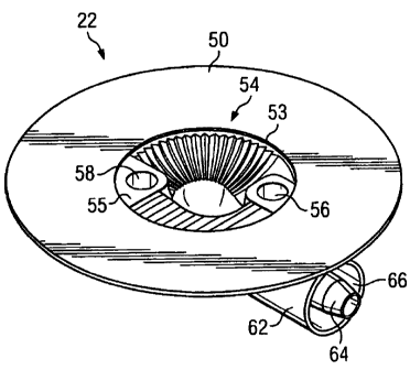
reduced pressure adapter 22. FIG. 2 provides a perspective view of the
underside of
reduced pressure adapter 22 showing the various structural elements within the
CA 02635617 2008-06-26
WO 2007/092397 PCT/US2007/003065
-10-
opening of reduced pressure adapter 22 that are adapted to contact the
distribution
manifold 24 (not*shown) of the wound dressing.
Reduced pressure adapter 22 generally comprises a base 50, which may be
adhered to the distribution manifold, and a conduit housing 62 coupled to the
base
50. Conduit housing 62 includes a primary conduit and a pair of ancillary
conduits.
The base 50 includes an aperture 53, which is positioned over the distribution
=
manifold and through which the liquids and gases (collectively referred to as
"fluids")
are drawn from the tissue site. A significant feature of improved reduced
pressure
adapter 22 is the presence of channel elements positioned near and in fluid
communication with aperture 53 and the effective way in which the channel
elements
direct liquid into the primary conduit for drainage. The routing of liquids
into the
primary conduit maintains the ancillary conduits of the system open for
pressure
measurement purposes.
Referring to FIG. 2, the conduit housing 62 of reduced pressure adapter 22
includes a recessed region 54 defining an entry surface 55. The primary
conduit
terminates on the entry surface 55 at a primary port 60, which is centrally
located at
an apex of the recessed region 54. The ancillary conduits terminate on the
entry
surface 55 at ancillary ports 56 and 58. The ancillary ports are positioned
near
diametrically opposing edges of aperture 53.
. A-second end of the primary conduit terminates at a primary lumen interface-
64. Primary lumen interface 64 is generally centrally positioned within
aperture 66.
Ancillary lumen interfaces 48, 49 (see FIG. 5) to the ancillary conduits also
are
located within aperture 66 and .are described in more detail below.
FIG. 3 provides a plan view (from above) of reduced pressure adapter 22.
The conduit housing 62 is preferably "elbow" shaped; however, the conduit
housing
may be configured at any desired angle-or may extend perpendicularly from base
50.
In the elbow configuration illustrated in FIG. 3, reduced pressure adapter 22
is seen
to comprise base 50 and a centrally positioned conduit housing 62. Conduit
housing
62 includes an elbow region 68, and the conduit housing 62 internally
comprises
conduits between the ports 56, 58, 60 and the ancillary and primary lumen
interfaces
48, 49, 64.
CA 02635617 2008-06-26
WO 2007/092397 PCT/US2007/003065
-11-
FIGS. 4, 5 & 6 show side, and end views of the reduced pressure adapter 22.
Reduced pressure adapter 22,-as seen in the side view shown in FIG. 4, is of
low
profile construction with base 50 defining its lateral limits. As indicated
above, base
50 may be directly adhered to the distribution manifold or may be positioned
and
adhered using the drape of the wound dressing: The reduced pressure adapter 22
is
positioned on distribution manifold such that the aperture 53 (not seen in
this view) of
base 50 is in direct contact with the distribution manifold. In the view shown
in FIG.
4, primary lumen interface 64 extends centrally out from conduit housing 62
and is
surrounded by aperture 66. Conduits extend through the material of reduced
pressure adapter 22 between the tubing interfaces and recessed region 54, as
described above. The elbow region 68 redirects fluid flow from the wound
dressing
positioned beneath reduced pressure adapter 22 to an angle associated with
interface 64 in a manner that allows the system to be placed on the wound
dressing
and be maintained close to the wound dressing surface.
FIG. 5 is an end view of the same structure shown in FIG. 4 with the-
configuration of elbow region 68 and the internal configuration of conduit
housing 62
more clearly shown. In this view, the same components associated with adhering
reduced pressure adapter 22 to the wound dressing are disclosed. Base 50 and
aperture 54 are positioned as indicated in FIG. 4. Conduit housing 62 is shown
as it
would be positioned to receive a section of tubing for connection to the
balance of
the system of the present invention.
Internal to conduit housing 62 are primary lumen interface 64 and ancillary
lumen interfaces 48 and 49. Ancillary lumen interfaces 48 and 49 align with
the
corresponding lumens in the delivery tubing by placing the primary lumen in
the
tubing over the primary lumen interface 64. The structure, of one embodiment
of
multi-lumen tubing used in conjunction with the improved reduced pressure
adapter
structure of the present invention is described in more detail below.
FIG. 6 provides essentially the same view of reduced pressure adapter 22 as
that of FIG. 4 but from the opposite side. Structurally, the elements shown
are the
same as those shown and described with FIG. 4, which is indicative of the
lateral
(and to an extent, radial) symmetry of the connector. Unless otherwise
indicated, the
materials used to construct the improved connector of the present invention
may be
CA 02635617 2008-06-26
WO 2007/092397 PCT/US2007/003065
-12-
selected from a number of materials known in the art that provide the
necessary
flexibility and comfort to the patient while maintaining sufficient rigidity
or resilience to
maintain the open lumens* that are integral to the* reduced pressure adapter
function.
FIG. 7 provides a plan view (from below) of reduced pressure adapter 22 and
clarifies the structure and function of the various features and elements
within
recessed region 54 that serve to preference liquids and other non-gaseous
fluids
away from the ancillary ports 56, 58. In this view, base 50 is shown
surrounding the
edge of recessed region 54. Ancillary ports 56 and 58 are shown positioned as
indicated, with associated conduits extending internally from ports 56 and 58
to
ancillary lumen interfaces (hidden and not shown in this view). Primary port
60 can
be seen centrally located within aperture 54. The primary conduit extends
(hidden
and not shown in this view) from primary port 60 through primary lumen
interface 64.
The specific structures within recessed region 54 that serve to conduct liquid
into the
primary conduit, and thereby allow the ancillary conduits to remain
unobstructed are
described in more detail below with respect to FIG. 9.
FIG. 8 shows an alternate exemplary embodiment of the base associated with
the reduced pressure adapter of the present invention. In this view (the same
perspective as that of FIG. 7) added features to the underside surface of
alternate
base 52 are shown. These features, molded into the structure of base 52,
include
base serrated guide channels 70, perimeter collection channels 72, and
intermediate
collection channels 74. The objective of these channels is to direct liquid
away from
the two ancillary measurement ports 56, 58 and into the primary port 60. Base
serrated guide channels 70 are positioned and oriented on base 50 to directly
capture and channel at least half of the liquids being drawn into the reduced
pressure adapter, and indirectly channel a major portion of the balance of the
liquids
being drawn in. The spaced, radially-oriented arrangement of base serrated
guide
channels 70 funnels liquids away from the ancillary ports and into the primary
port.
In addition, perimeter collection channels 72 and intermediate collection
channels 74
redirect the flow of liquids that are being drawn in between the radially-
oriented guide
channels 70 into the guide channels 70 and away from the ancillary ports. An
example of this redirected flow is shown in FIG. 8 with bolded flow indication
arrows.
CA 02635617 2008-06-26
WO 2007/092397 PCT/US2007/003065
-13-
Reference is now made to FIG. 9 for a more detailed description of the
features *and elements contained within the recessed region of conduit
h6using'62.
These features are positioned on the entry surface 55 of the recessed region
54 and
are structured to preference liquids and other non-gaseous exudates away from
the
ancillary ports 56, 58 and into the primary port 60. In this view, primary
port 60 is
shown centrally positioned within recessed region 54 and extending from the
central
location to one side of recessed region 54. Ancillary ports 56 and 58 are
likewise
disclosed in this view, positioned to either side of the central location of
primary port
60. In this view, ancillary ports 56 and 58 are circular openings (each with
raised
circumferential edges) that extend toward a drainage point that opens into an
internal
conduit extending to the associated ancillary lumen interface (not shown). The
openings of the conduits can be seen within the confines of ancillary ports 56
and
58.
Four basic features within the structure shown in FIG. 9 are positioned to
preference liquid into the primary port 60 of the reduced pressure adapter 22.
The
first such structure is simply the placement of the ancillary ports 56 and 58
near the
perimeter of the aperture 53 at a level that is close to the surface of the
distribution
manifold when the reduced pressure adapter 22 is positioned thereon. In other
words, when the reduced pressure adapter 22 is positioned on the wound
dressing,
the ancillary ports 56 and 58 are in contact, or are nearly in contact, with
the surface
of the distribution manifold. In this manner, the likelihood of splashed or
agitated
liquid being directed into these ports is minimized.
The remaining three features that direct liquids into the primary port are
structural serrated channels formed on various portions of the entry surface
55 of
recessed region 54. A first linear serrated channel section 42 is positioned
in
association with the approximately half circle section of recessed region 54
that is
associated with ancillary port 58. The material that comprises the ceiling of
this
section of recessed region 54 covers and contains the conduit that extends
between
ancillary port 58 and its interface (not shown). This ceiling or wall is
configured with
an array of serrated channels or striations that directs liquids that fall
upon this
surface towards the primary port at the center of the recessed region 54. Any
liquids
that are drawn into the opening and fall upon this portion of the entry
surface 55
CA 02635617 2008-06-26
WO 2007/092397 PCT/US2007/003065
-14-
would be channeled directly into primary port 60, rather than being directed
into
ancillary port 58.
A similar configuration is constructed in an approximately one-third circular
radial serrated channel section 44. Insofar as no internal conduit is
contained within
this section of the recessed region 54, the serrated channels in section 44
may
extend deeper and more directly to the primary port 60. These radial serrated
channels are directed from the perimeter of aperture 54 towards the apex of
the
recessed region 54 that drains into primary port 60. These radial striations
or
channels extend from a radius adjacent ancillary port 58 radially around
approximately one-third of the circle to a radius adjacent ancillary port 56.
Any
liquids that fall upon this portion of the recessed region 54 will be directed
centrally to
primary port 60, rather than being conducted to either of the ancillary ports.
Finally, the wall section that supports ancillary port 56 at the point at
which the
ancillary port 56 overhangs primary port 60 is structured with serrated or
striated
channels 46 that extend downward (upward in the normal positioning of the
connector) from the opening of ancillary port 56 towards the opening of
primary port
60.
As described above, the various internal features and elements of the
recessed region 54 are structured to draw liquid from most points within the
recessed region 54 towards the centrally located primary port 60. Only liquid
that . .
enters directly into ancillary port 56 or 58 would likely be drawing into an
ancillary
lumen. Insofar as little or no suction is occurring at these ports, this
structure greatly
reduces the likelihood of obstructions in the form of liquid or material
blockages in an
ancillary lumen.
Reduced Pressure Delivery Tube
Reference is now made to FIGS. 10 and 11 for a detailed description of the
structure of an improved reduced pressure delivery tube 80 operable in
association
with the system of an exemplary embodiment of the present invention. The
reduced
pressure delivery tube 80 preferably includes a primary central lumen 82 and
ancillary lumens 84 and 86. Ancillary lumens 84 and 86 are generally used for
taking pressure measurements. In FIG. 11, fluid flow designated by the block
arrows
is shown as it would be directed through primary lumen 82 while ancillary
lumens 84
CA 02635617 2008-06-26
WO 2007/092397 PCT/US2007/003065
-15-
and 86 remain generally free of liquid or any non-gaseous matter. The cross-
sectional perspectives shown in' both FIGS. 10 *and 11 'disclose the relative
cross-
sectional diameters of the primary lumen 82 as compared with the ancillary
lumens
84 and 86. Delivery device 80 has an oval cross-section, which optimizes
flexibility
without allowing for the collapse of any of the described lumens. This cross-
sectional shape also orients the ancillary lumens 84 and 86 so that the lumens
align
appropriately with the interfaces on the improved reduced pressure adapter
described above.
Dynamic Method of Measuring Wound Pressure
The system of the present invention also includes an improved and dynamic
method of measuring the wound pressure that overcomes problems inherent with
current reduced pressure wound treatment control systems. 'Various methods
have
been developed in the art to control the operation of reduced pressure wound
treatment products and systems to insure that the wound pressure is maintained
and
that the therapy is safe by effective operation of the prescribed regimens.
Currently,
wound pressure is measured with the outer lumen or lumens of a multi-lumen
tube
that are commoned together and connected to one pressure sensor. This
structure
can suffer certain problems if liquid enters the lumens or they become
blocked. If
such liquid intrusion or blockages occur, the system can become unstable and
alarms or indicators related to pressure become unreliable. Various mechanical
remedies for these problems have been attempted and some have been partially
successful. Ultimately, however, a system such as described in the prior art
will be
challenged with liquid in the control lumen unless there is a physical barrier
placed
against the ingress of liquid into the measurement lumen(s). One goal of the
present
invention is a system that is more reliable and more robust when challenged
with
extremes of therapy, as compared to current single sensor measurement lumen
systems.
Reference is made to FIG. 12 wherein the system of an exemplary
embodiment of the present invention and the functional relationship of its
components are disclosed. The system incorporates two wound pressure sensors
40a and 40b in the system instrumentation that extend separately (through
discrete
lumens or conduits) from the instrumentation to the reduced pressure adapter
and
CA 02635617 2008-06-26
WO 2007/092397 PCT/US2007/003065
-16-
are not commoned until the discrete lumens combine at the interface of the
reduced
pressure adapter and the distribution manifold. As indicated above, the
reduced
pressure adapter incorporates two separate pressure sensing ports as well as
the
fluid path through fluid chamber 18 to the reduced pressure pump 38 in the
system
instrumentation. Inside the system instrumentation, each of the ancillary
measurement lumen conduits is fitted with a=solenoid valve 92 and 94 which
will
relieve pressure to the wound at the end of therapy, during intermittent
therapy, or if
required to clear blockages- These valves, as well as .a similar valve
associated with
the reduced pressure source 38, are controlled by microprocessor/controller
90.
Microprocessor/controller 90 likewise controls the operation of reduced
pressure
pump 38 and receives data from first and second pressure measurement devices
40a and 40b. The microprocessor/controller 90 is programmed to monitor the
wound
pressure through the two readings associated with the two ancillary lumen
paths. In
instances where liquid enters one of the lumens, the liquid will cause a delay
in the
pressure change response time of that lumen versus the clear lumen. As the
blockage becomes more acute so will the delay. When a delay is detected, the
system will control the wound pressure according to that of the open lumen and
will
try to clear the liquid from the blocked lumen by opening the appropriate
valve to
atmosphere. The preferred programming will try to clear the blockage in this
manner
several times. If the system is not successful in clearing the blockage, the
programming will, from that point on, ignore the affected lumen and control
the
system with the remaining clear lumen. The reduced pressure adapter design of
the
present invention, as described above, is such as to maximize the chances of
having
at least one clear ancillary measurement lumen at any given time.
Reduced Pressure Adapter with Rotating Function
Currently, reduced pressure adapters in RPWT systems typically allow for the
effective connection of reduced pressure wound therapy to the wound, but do
not
allow for the tube connection point to be repositioned (for example, in the
event that
the patient is susceptible to skin breakdown) or for a situation where the
user has
incorrectly positioned the reduced pressure adapter (for example, in the event
that
the reduced pressure adapter is facing in the wrong direction). In such
instances,
the user must remove and discard the reduced pressure adapter, and in some
CA 02635617 2008-06-26
WO 2007/092397 PCT/US2007/003065
-17-
instances the drape, which causes discomfort and is a nuisance to the patient
and
user as well as an additional cost. Providing a rotation or swivel function to
the
reduced pressure adapter enables repositioning the tube without having to
remove
and relocate the reduced pressure adapter. This ability assists in any
situation
where the tubing requires relocation to avoid- tissue damage. - One goal of
the
present invention is to provide a reduced pressure adapter structure that
allows for
easy relocation of the tubing without removing and relocating the reduced
pressure
adapter or the wound dressing.
Reference is made to FIGS. 13 and 14 for a description of the configuration of
an alternate preferred embodiment of the reduced pressure adapter structure.
The
reduced pressure adapter 110 shown in FIG. 13 employs a hard plastic inner
core
that forms a bearing surface to enable a rubber o-ring to seal against it and
also to
enable the bearing surface to slide past with relatively low friction. Bonded
to the
hard plastic inner core is a soft thermoplastic or elastomeric polymer that
acts as a
protective and cushioning cover. FIGS. 13 and 14 show the various circular
ring
components that go together to make up the swivel connection of the present
invention. A top rotating PVC component 112 covers a top ABS insert ring 114
which itself is surrounded by a rubber o-ring 116. A bottom ABS insert ring
118 is
shown that holds o-ring 116 captive between it and the top ABS insert 114.
Each of
these rings is then fitted within the bottom PVC ring 120 which comes into
contact
with the base of the reduced pressure adapter and/or with the wound dressing
itself.
The internal features.and elements associated with the reduced pressure
adapter as described above in conjunction with a non-rotating embodiment are
equally applicable here and may be integrated into the inside structure of top
rotating
PVC component 112 by direct molding of the component or by positioning a
molded
insert into a shell to for rotating component 112. In any event, the same
benefits of
the liquid preferencing structures surrounding the lumen ports described above
are
obtainable with the rotating functionality of the alternate embodiment
described.
[00011 FIG. 14 discloses the same components mentioned above as they would be
assembled and thereby shows in clearer detail the manner in which the
components
interlock and rotate with or against each other. In this view, the captive o-
ring 116 is
also shown to provide a proper seal for the internal reduced pressure chamber
CA 02635617 2008-06-26
WO 2007/092397 PCT/US2007/003065
-18-
formed by the reduced pressure adapter 110. In this view it is also clear how
the
internal features and elements in the port opening may be appropriately
positioned
on the underside of top PVC component 112 to serve the function of
preferencing
liquid to the primary conduit as described above.
Reduced Pressure Adapter with Microorganism Indication
Current reduced pressure treatment systems do not generally alert the
caregiver to the presence of microorganisms in wound dressings. Many of these
microorganisms can be-significant factors in controlling infection at the
wound site.
One goal of the present invention is to provide a system that will alert the
caregiver
to significant levels of key microorganisms under the classification of
aerobic, non-
aerobic, gram positive and gram negative. The response or indication is in the
form
of color patterns discretely reflecting the four classifications mentioned
above.
A volatile organic compound (VOC) sensitive strip mounted on the reduced
pressure adapter or its associated drape is utilized in certain embodiments.
When
exposed to the targeted VOC known to form in the presence of certain
microorganisms, a color pattern becomes apparent and thereby identifies the
type of
microorganism present in the wound fluid. Referencing FIGS. 15 and 16, a
reduced
pressure adapter 122 includes a base 124 and a conduit housing 130 similar to
that
described previously with reference to FIGS. 2-9. The positioning of a VOC
sensitive
panel 128 in a recessed region 126 of the conduit housing 130 is shown. In
FIG. 16,
it can be seen that given the translucent or transparent character of the
material from
which the reduced pressure adapter 122 is constructed, the VOC sensitive panel
128
can be visually inspected even from the exterior while the reduced pressure
adapter
122 is in place with base 124 in position against the distribution manifold of
the
wound dressing. The preferable positioning of this VOC sensitive panel 128 is
therefore within the recessed region 126 near the periphery of the recessed
region
126 as shown. FIG. 15 shows more clearly the placement of this VOC sensitive
panel within the recessed region 126 where it is constantly exposed to the
fluid
materials being drawn from the wound. Alternate placements of the panels are
possible as long as sufficient exposure to wound fluids exists.
[0002] It should be apparent from the foregoing that an invention having
significant
advantages has been provided. While the invention is shown in only a few of
its
CA 02635617 2011-06-03
-19-
forms, it is not just limited but is susceptible to various changes and
modifications.