Note: Descriptions are shown in the official language in which they were submitted.
CA 02693834 2013-01-23
WO 2009/011822
PCT/US2008/008586
SECURE LOCALIZATION FOR 802.11 NETWORKS
WITH FINE GRANULARITY
BACKGROUND
1. Field
The preferred embodiments of the present invention relate to wireless
networks, and to security and to access control within networks.
2. Background Discussion
Networks and Internet Protocol:
There are many types of computer networks, with the Internet having the
most notoriety. The Internet is a worldwide network of computer networks.
Today,
the Internet is a public and self-sustaining network that is available to many
millions of users. The Internet uses a set of communication protocols called
TCP/IP (i.e., Transmission Control Protocol/Internet Protocol) to connect
hosts.
The Internet has a communications infrastructure known as the Internet
backbone. Access to the Internet backbone is largely controlled by Internet
Service Providers (ISPs) that resell access to corporations and individuals.
With respect to IP (Internet Protocol), this is a protocol by which data can
be sent from one device (e.g., a phone, a PDA [Personal Digital Assistant], a
computer, etc.) to another device on a network. There are a variety of
versions of
1
CA 02693834 2010-01-13
WO 2009/011822
PCT/US2008/008586
IP today, including, e.g., IPv4, IPv6, etc. Each host device on the network
has at
least one IP address that is its own unique identifier. IP is a connectionless
protocol. The connection between end points during a communication is not
continuous. When a user sends or receives data or messages, the data or
messages are divided into components known as packets. Every packet is
treated as an independent unit of data.
In order to standardize the transmission between points over the Internet
or the like networks, an OSI (Open Systems Interconnection) model was
established. The OSI model separates the communications processes between
two points in a network into seven stacked layers, with each layer adding its
own
set of functions. Each device handles a message so that there is a downward
flow through each layer at a sending end point and an upward flow through the
layers at a receiving end point. The programming and/or hardware that provides
the seven layers of function is typically a combination of device operating
systems, application software, TCP/IP and/or other transport and network
protocols, and other software and hardware.
Typically, the top four layers are used when a message passes from or to
a user and the bottom three layers are used when a message passes through a
device (e.g., an IP host device). An IP host is any device on the network that
is
capable of transmitting and receiving IP packets, such as a server, a router
or a
workstation. Messages destined for some other host are not passed up to the
upper layers but are forwarded to the other host. The layers of the OSI model
are listed below. Layer 7 (i.e., the application layer) is a layer at which,
e.g.,
communication partners are identified, quality of service is identified, user
authentication and privacy are considered, constraints on data syntax are
identified, etc. Layer 6 (i.e., the presentation layer) is a layer that, e.g.,
converts
incoming and outgoing data from one presentation format to another, etc. Layer
5
(i.e., the session layer) is a layer that, e.g., sets up, coordinates, and
terminates
conversations, exchanges and dialogs between the applications, etc. Layer-4
2
CA 02693834 2010-01-13
WO 2009/011822
PCT/US2008/008586
(i.e., the transport layer) is a layer that, e.g., manages end-to-end control
and
error-checking, etc. Layer-3 (i.e., the network layer) is a layer that, e.g.,
handles
routing and forwarding, etc. Layer-2 (i.e., the data-link layer) is a layer
that, e.g.,
provides synchronization for the physical level, does bit-stuffing and
furnishes
transmission protocol knowledge and management, etc. The Institute of
Electrical
and Electronics Engineers (IEEE) sub-divides the data-link layer into two
further
sub-layers, the MAC (Media Access Control) layer that controls the data
transfer
to and from the physical layer and the LLC (Logical Link Control) layer that
interfaces with the network layer and interprets commands and performs error
recovery. Layer 1 (i.e., the physical layer) is a layer that, e.g., conveys
the bit
stream through the network at the physical level. The IEEE sub-divides the
physical layer into the PLCP (Physical Layer Convergence Procedure) sub-layer
and the PMD (Physical Medium Dependent) sub-layer.
Wireless Networks:
Wireless networks can incorporate a variety of types of mobile devices,
such as, e.g., cellular and wireless telephones, PCs (personal computers),
laptop
computers, wearable computers, cordless phones, pagers, headsets, printers,
PDAs, etc. For example, mobile devices may include digital systems to secure
fast wireless transmissions of voice and/or data. Typical mobile devices
include
some or all of the following components: a transceiver (i.e., a transmitter
and a
receiver, including, e.g., a single chip transceiver with an integrated
transmitter,
receiver and, if desired, other functions); an antenna; a processor; one or
more
audio transducers (for example, a speaker or a microphone as in devices for
audio communications); electromagnetic data storage (such as, e.g., ROM, RAM,
digital data storage, etc., such as in devices where data processing is
provided);
memory; flash memory; a full chip set or integrated circuit; interfaces (such
as,
e.g., USB, CODEC, UART, PCM, etc.); and/or the like.
Wireless LANs (WLANs) in which a mobile user can connect to a local
area network (LAN) through a wireless connection may be employed for wireless
3
CA 02693834 2010-01-13
WO 2009/011822
PCT/US2008/008586
communications. Wireless communications can include, e.g., communications
that propagate via electromagnetic waves, such as light, infrared, radio,
microwave. There are a variety of WLAN standards that currently exist, such
as,
e.g., Bluetooth, IEEE 802.11, and HomeRF.
By way of example, Bluetooth products may be used to provide links
between mobile computers, mobile phones, portable handheld devices, personal
digital assistants (PDAs), and other mobile devices and connectivity to the
Internet. Bluetooth is a computing and telecommunications industry
specification
that details how mobile devices can easily interconnect with each other and
with
non-mobile devices using a short-range wireless connection. Bluetooth creates
a
digital wireless protocol to address end-user problems arising from the
proliferation of various mobile devices that need to keep data synchronized
and
consistent from one device to another, thereby allowing equipment from
different
vendors to work seamlessly together. Bluetooth devices may be named
according to a common naming concept. For example, a Bluetooth device may
possess a Bluetooth Device Name (BDN) or a name associated with a unique
Bluetooth Device Address (BDA). Bluetooth devices may also participate in an
Internet Protocol (IP) network. If a Bluetooth device functions on an IP
network, it
may be provided with an IP address and an IP (network) name. Thus, a
Bluetooth Device configured to participate on an IP network may contain, e.g.,
a
BDN, a BDA, an IP address and an IP name. The term "IP name" refers to a
name corresponding to an IP address of an interface.
An I.E.E.E. standard, I.E.E.E. 802.11, specifies technologies for wireless
LANs and devices. Using 802.11, wireless networking may be accomplished
with each single base station supporting several devices. In some examples,
devices may come pre-equipped with wireless hardware or a user may install a
separate piece of hardware, such as a card, that may include an antenna. By
way of example, devices used in 802.11 typically include three notable
elements,
whether or not the device is an access point (AP), a mobile station (STA), a
4
CA 02693834 2010-01-13
WO 2009/011822
PCT/US2008/008586
bridge, a PCMCIA card or another device: a radio transceiver; an antenna; and
a
MAC (Media Access Control) layer that controls packet flow between points in a
network.
In addition, Multiple Interface Devices (MIDs) may be utilized in some
wireless networks. MIDs may contain two independent network interfaces, such
as a Bluetooth interface and an 802.11 interface, thus allowing the MID to
participate on two separate networks as well as to interface with Bluetooth
devices. The MID may have an IP address and a common IP (network) name
associated with the IP address.
Wireless network devices may include, but are not limited to Bluetooth
devices, Multiple Interface Devices (MIDs), 802.11x devices (I.E.E.E. 802.11
devices including, e.g., 802.11a, 802.11b and 802.11g devices), HomeRF (Home
Radio Frequency) devices, Wi-Fl (Wireless Fidelity) devices, GPRS (General
Packet Radio Service) devices, 3G cellular devices, 2.5G cellular devices, GSM
(Global System for Mobile Communications) devices, EDGE (Enhanced Data for
GSM Evolution) devices, TDMA type (Time Division Multiple Access) devices, or
CDMA type (Code Division Multiple Access) devices, including CDMA2000.
Each network device may contain addresses of varying types including but not
limited to an IP address, a Bluetooth Device Address, a Bluetooth Common
Name, a Bluetooth IP address, a Bluetooth IP Common Name, an 802.11 IP
Address, an 802.11 IP common Name, or an I.E.E.E. MAC address. Wireless
networks can also involve methods and protocols found in, e.g., Mobile IP
(Internet Protocol) systems, in PCS systems, and in other mobile network
systems. With respect to Mobile IP, this involves a standard communications
protocol created by the Internet Engineering Task Force (I.E.T.F.). With
Mobile
IP, mobile device users can move across networks while maintaining their IP
Address assigned once. See Request for Comments (RFC) 3344. NB: RFCs are
formal documents of the Internet Engineering Task Force (IETF).
CA 02693834 2010-01-13
WO 2009/011822
PCT/US2008/008586
Mobile IP enhances Internet Protocol (IP) and adds means to forward
Internet traffic to mobile devices when connecting outside their home network.
Mobile IP assigns each mobile node a home address on its home network and a
care-of-address (CoA) that identifies the current location of the device
within a
network and its subnets. When a device is moved to a different network, it
receives a new care-of address. A mobility agent on the home network can
associate each home address with its care-of address. The mobile node can
send the home agent a binding update each time it changes its care-of address
using, e.g., Internet Control Message Protocol (ICMP).
In basic IP routing (e.g., outside mobile IP), routing mechanisms rely on
the assumptions that each network node always has a constant attachment point
to, e.g., the Internet and that each node's IP address identifies the network
link it
is attached to. In this document, the terminology "node" includes a connection
point, which can include, e.g., a redistribution point or an end point for
data
transmissions, and which can recognize, process and/or forward communications
to other nodes. For example, Internet routers can look at, e.g., an IP address
prefix or the like identifying a device's network. Then, at a network level,
routers
can look at, e.g., a set of bits identifying a particular subnet. Then, at a
subnet
level, routers can look at, e.g., a set of bits identifying a particular
device. With
typical mobile IP communications, if a user disconnects a mobile device from,
e.g., the Internet and tries to reconnect it at a new subnet, then the device
has to
be reconfigured with a new IP address, a proper netmask and a default router.
Otherwise, routing protocols would not be able to deliver the packets
properly.
Localization:
A problem related to background technologies involves the inability to be
able to determine the location of an untrusted user in a wireless network with
a
high degree of accuracy. The present invention overcomes problems in the
background art, and provides a mechanism that can, e.g., prevent spoofing and
make collusion as difficult as possible.
6
CA 02693834 2013-01-23
The present assignees filed other patent application(s) related to secure
localization that did not have all of the benefits of the present invention.
See, e.g.,
Location Dependent Key Management in Sensor Networks Without Using
Deployment Knowledge set forth in U.S. Patent No. 7,508,788; and Secure
Wireless
User Localization Scheme Using Transmission Range Variation as set forth in
U.S.
Patent No. 7,576,694.
For reference, FIG. 1 depicts a scheme as described in the above-referenced
U.S. Patent No. 7,576,694. With reference to FIG. 1, generally the deployment
of a
wireless network involves at least one wireless subnet such as wireless subnet
101,
in which wireless user devices such as wireless communication device 102 are
connected to at least one wired subnet 1016 over a radio communication
channel 103 to one or more Access Points, such as Access Point (AP) 105, and
at
least one router, such as router 1014. As shown, the wireless user device 102
is
associated with AP2 105, and can communicate with AP2 105 via the wireless
communication link 103. This background embodiment of the '566 patent
application
is based on the location estimation being carried out by the network using at
least
three APs: 104; 105; 106. In accordance with the concepts therein, the
property of
a current AP that enables it to transmit at different power levels is
exploited. Use of
a different power level will result in a different transmission range for the
AP. The
embodiment assumes that each location in the network system under
consideration
is within the maximum transmission range of multiple APs. Each AP in the
system at
a given time associates a "nonce", or random number, with each power level and
securely transmits each nonce at that power level to the user whose location
is to be
determined. As a result, every location will have a unique set of nonces from
multiple APs associated with it at any given point in time. This set depends
on the
power levels that each AP has to use to reach the location of interest, which
7
CA 02693834 2010-01-13
WO 2009/011822
PCT/US2008/008586
in turn depends on the distance from the location to the various APs. Wireless
user device 102 will be able to "hear" a particular set of nonces depending on
its
location with respect to the APs. The user device 102 is expected to securely
transmit back the nonces received. The location of the user device 102 then
can
be determined based on the set of nonces transmitted back. The presence of
multiple (e.g., at least three) APs makes it possible to securely determine
the
location of a wireless user device in the wireless network. An AP Controller
(APC) 1015 is a central entity that manages all of the APs and user devices of
the network. The APC 1015 has detailed information about the user devices and
APs, which may be obtained via repeated SNMP (Simple Network Management
Protocol) queries. The APC 1015 either acts as a gateway router or controls a
gateway router in order to set up an access control list for Intranet or
Internet
access. APC 1015 controls the localization process and is assumed to have the
nonce set corresponding to each location within the deployment site. This may
be obtained during a pre-deployment phase and may be maintained in a
database (e.g., location table). The APC 1015 is connected to the various APs
(104, 105, 106) in the network via the backbone wired network (1010, 1011,
1012, 1013, 1014). Fig. 1 also illustrates wired communication links 107, 108,
and 109. The APs (104, 105, 106) act as a bridge between the internal wired
and wireless subnet domains 1016 and 101. The APs (104, 105, 106) can be any
commercially available access point with the ability to transmit at various
power
levels. Such multiple power level transmission capability is currently a
feature
built into various commercially available APs such as Cisco AP1100, D-Link
DWL-2100AP, and others. A secure localization method according to one
embodiment of the '566 application is based on transmission of nonces (random
numbers) at different power levels from various APs. The location of a
wireless
user can be estimated depending on the set of nonces received by the user
device and transmitted back to the APC via the APs.
8
CA 02693834 2010-01-13
WO 2009/011822
PCT/US2008/008586
Illustrative Architecture:
FIG. 6 depicts some illustrative architectural components that can be
employed in some illustrative and non-limiting implementations including
wireless
access points to which client devices communicate. In this regard, FIG. 6
shows
an illustrative wireline network 20 connected to a wireless local area network
(WLAN) generally designated 21. The WLAN 21 includes an access point (AP)
22 and a number of user stations 23, 24. For example, the wireline network 20
can include the Internet or a corporate data processing network. For example,
the access point 22 can be a wireless router, and the user stations 23, 24 can
be,
e.g., portable computers, personal desk-top computers, PDAs, portable voice-
over-IP telephones and/or other devices. The access point 22 has a network
interface 25 linked to the wireline network 21, and a wireless transceiver in
communication with the user stations 23, 24. For example, the wireless
transceiver 26 can include an antenna 27 for radio or microwave frequency
communication with the user stations 23, 25. The access point 22 also has a
processor 28, a program memory 29, and a random access memory 31. The
user station 23 has a wireless transceiver 35 including an antenna 36 for
communication with the access point station 22. In a similar fashion, the user
station 24 has a wireless transceiver 38 and an antenna 39 for communication
to
the access point 22. By way of example, in some embodiments an authenticator
could be employed within such an access point (AP) and/or a supplicant or peer
could be employed within a mobile node or user station.
FIG. 7 shows an illustrative computer or control unit that can be used to
implement computerized process steps, to be carried out by devices, such as,
e.g., an access point, a client device, a computer, a user station, a source
node
or destination node in some embodiments. In some embodiments, the computer
or control unit includes a central processing unit (CPU) 322, which can
communicate with a set of input/output (I/O) device(s) 324 over a bus 326. The
I/O devices 324 can include, for example, a keyboard, monitor, and/or other
devices. The CPU 322 can communicate with a computer readable medium
(e.g., conventional volatile or non-volatile data storage devices) 328
(hereafter
9
CA 02693834 2010-01-13
WO 2009/011822
PCT/US2008/008586
"memory 328") over the bus 326. The interaction between a CPU 322, I/O
devices 324, a bus 326, and a memory 328 can be like that known in the art.
Memory 328 can include, e.g., data 330. The memory 328 can also store
software 338. The software 338 can include a number of modules 340 for
implementing the steps of processes. Conventional programming techniques
may be used to implement these modules. Memory 328 can also store the
above and/or other data file(s). In some embodiments, the various methods
described herein may be implemented via a computer program product for use
with a computer system. This implementation may, for example, include a series
of computer instructions fixed on a computer readable medium (e.g., a
diskette, a
CD-ROM, ROM or the like) or transmittable to a computer system via and
interface device, such as a modem or the like. A communication medium may be
substantially tangible (e.g., communication lines) and/or substantially
intangible
(e.g., wireless media using microwave, light, infrared, etc.). The computer
instructions can be written in various programming languages and/or can be
stored in memory device(s), such as semiconductor devices (e.g., chips or
circuits), magnetic devices, optical devices and/or other memory devices. In
the
various embodiments, the transmission may use any appropriate
communications technology.
SUMMARY
The preferred embodiments improve upon existing systems and methods
in the background art.
According to the preferred embodiments, through the use of wireless-
capable desktop computers in the vicinity, one can securely determine the
location of an untrusted user with office level granularity. According to some
preferred embodiments, wireless access points (APs) broadcast tokens at
different power levels. Because of the limits of wireless communications, each
untrusted user in the system will only be able to hear a subset of those
tokens.
CA 02693834 2010-01-13
WO 2009/011822
PCT/US2008/008586
According to the preferred embodiments, the tokens are returned to a
controller
(e.g., an administrative machine) that compares the tokens received with
profiles
of different locations. Preferably, when a match is found, the system
transitions
from "macro" to "pico" modes. In the "pico" mode, the controller preferably
uses
the general location information learned in the "macro" phase. The controller
preferably selects machines within and around the area and generates new
tokens for them to broadcast. The client also preferably returns these tokens
to
the controller, which again compares them against known location profiles.
Based on these two steps, the controller determines the location of the
client.
According to some embodiments, a method of localizing mobile client
devices within a geographical area, comprising: a) having an Access Point
Controller generate tokens and provide the tokens to a plurality of Access
Points
within a geographical area; b) having the Access Points transmit said tokens
for
receipt by client devices within said geographical area; c) having at least
one
client device within said geographical area inform the Access Point Controller
of
the tokens that it receives from the Access Points; and d) having the Access
Point Controller determine a Macro-Location of the client device based on the
tokens received by the client device; e) having the Access Point Controller
generate new tokens for transmission to a plurality of computers distributed
at
least within the Macro-Location within said geographical area to wirelessly
transmit to said client device; f) having the client device inform the Access
Point
Controller of the new tokens that it receives from the computers distributed
within
said geographical area; and g) having the Access Point Controller determine a
Pico-Location of the client device based on the new tokens received by the
client
device.
In some examples, wherein said computers include desk top or personal
computers configured with an 802.11 wireless interface and adapted to operate
as a Pico-AP. In some examples, the method further includes performing access
control of said client device based on the Pico-Location of the client device.
In
11
CA 02693834 2010-01-13
WO 2009/011822
PCT/US2008/008586
some examples, the method further includes performing security functions
within
said client device based on the Pico-Location of the client device, such as,
e.g.,
including performing or limiting performance of applications or programs on
said
client device based on the Pico-Location of the client device.
According to some other embodiments, a method of location mapping for
localizing mobile client devices within a geographical area is provided that
includes: a) having an Access Point Controller generate tokens for a plurality
of
Access Points to transmit within a geographical area; b) having the Access
Points wirelessly transmit the tokens to computers distributed within the
geographical area; c) having the computers report to the Access Point
Controller
regarding the tokens received from the Access Points; d) having the Access
Point Controller develop statistical mapping of one or more regions within
said
geographical area based on comparisons of the tokens it sent out to Access
Points to transmit and tokens reported back to the Access Point Controller.
According to some other embodiments, an Access Point Controller for
localization of client devices within a geographical region, is provided that
includes: a) said controller being configured to generate tokens for
transmission
to a plurality of Access Points; b) said controller being configured to
transmit said
tokens to Access Points within a geographical area for subsequent wireless
transmission to client devices within the geographical area; c) said
controller
being configured to receive reports from said client devices within the
geographical area as to the tokens received from the Access Points; d) said
controller being configured to perform a Macro-Localization of a client device
based on the tokens received by the client device; e) said controller being
configured to generate new tokens for transmission to a plurality of computers
within at least a macro-localized region within said geographical area for
subsequent transmission to client devices; f) said controller being configured
to
receive reports from client devices within the macro-localized region within
the
geographical area as to the new tokens received from the computers; g) said
12
CA 02693834 2010-01-13
WO 2009/011822
PCT/US2008/008586
controller being configured to determine a Pico-Location of the client device
based on the new tokens received by the client device.
The above and/or other aspects, features and/or advantages of various
embodiments will be further appreciated in view of the following description
in
conjunction with the accompanying figures. Various embodiments can include
and/or exclude different aspects, features and/or advantages where applicable.
In addition, various embodiments can combine one or more aspect or feature of
other embodiments where applicable. The descriptions of aspects, features
and/or advantages of particular embodiments should not be construed as
limiting
other embodiments or the claims.
BRIEF DESCRIPTON OF THE DRAWINGS
The preferred embodiments of the present invention are shown by way of
example, and not limitation, in the accompanying figures, in which:
FIG. 1 is a architectural diagram showing a background system;
FIG. 2 is a schematic diagram depicting an illustrative environment within
which some embodiments of the present invention can be implemented;
FIG. 3 is an illustrative flow diagram depicting process steps to be carried
out in some illustrative embodiments of the invention;
FIG. 4 is a diagram showing illustrative architectural components in some
illustrative embodiments of the invention;
FIG. 5 is a schematic diagram depicting another illustrative environment
within which some embodiments of the present invention can be implemented;
13
CA 02693834 2010-01-13
WO 2009/011822
PCT/US2008/008586
FIG. 6 is an architectural diagram showing components of illustrative
access points and client devices in some illustrative environments within
which
embodiments of the present invention could be employed;
FIG. 7 is a schematic diagram showing an illustrative computer or control
unit that can be used to implement computerized process steps, to be carried
out
by devices, such as, e.g., an access point, a client device, a computer, etc.
DESCRIPTION OF THE PREFERRED EMBODIMENTS
While the present invention may be embodied in many different forms, a
number of illustrative embodiments are described herein with the understanding
that the present disclosure is to be considered as providing examples of the
principles of the various inventions described herein and that such examples
are
not intended to limit the invention to preferred embodiments described herein
and/or illustrated herein.
The Preferred Embodiments:
Wireless access points (APs) broadcast tokens at different power levels.
Because of the limits of wireless communications, each untrusted user in the
system will only be able to hear a subset of those tokens. According to the
preferred embodiments, the tokens are returned to a controller (e.g., an
administrative machine) that compares the tokens received with profiles of
different locations. Preferably, when a match is found, the system transitions
from "macro" to "pico" modes. In the "pico" mode, the controller preferably
uses
the general location information learned in the "macro" phase. The controller
preferably selects machines within and around the area and generates new
tokens for them to broadcast. The client also preferably returns these tokens
to
the controller, which again compares them against known location profiles.
Based on these two steps, the controller determines the location of the
client.
14
CA 02693834 2010-01-13
WO 2009/011822
PCT/US2008/008586
To further assist in the process, the system can employ a mapping mode,
which creates the aforementioned profile information. In some examples, this
mapping can be launched in an on-demand fashion to dynamically build policy
maps of any location.
Among other things, the preferred embodiments have substantial
advantages over prior systems and/or methods. Among other things, the present
solution can be multi-modal and can provide enhanced accuracy through the use
of two levels of localization. The present solution can replace the means by
which the tokens are generated over the background technologies; and, the
present solution can advantageously use the result of cryptographically secure
hash function to prevent a user from determining the context of the token
itself.
The idea of using, e.g., 802.11 complaint radios (which can be, e.g.,
relatively inexpensive) attached to all or many desktop computers or the like
in
an office setting has only recently been suggested. Substantially the only
technique to use this new architecture for security purposes relies upon the
measurement of the strength of signal received from the untrusted client. In
that
regard, signal strength measurement is the state of the art in this field.
However,
such can be an insecure practice. In the preferred embodiments herein, a
system incorporates this new capability into a larger system, which uses,
e.g., all
or many wireless devices and the generation of random tokens to assist in the
process of localization.
The present inventors have designed and implemented a preliminary
version of this architecture. Preliminary micro-benchmarking and system
characterization have yielded promising results. For example, the overhead of
this process has been kept very low in terms of both requisite bandwidth
(e.g., 33
bytes per token) and processing overhead (e.g., sub 1 millisecond to generate
30
tokens).
CA 02693834 2010-01-13
WO 2009/011822
PCT/US2008/008586
The present invention has substantial advantages over existing
technologies. For example, a notable advantage of the present scheme is not
only that it provides unforgeable proof of the location of an untrusted user,
but it
also does so with a high level of granularity. All work done outside of the
present
assignee(s) to this point relies upon measuring signal strength, which can
easily
be forged by an adversary. In using multiple power levels and then performing
our broadcasts in multiple modes, we can be sure that the location can be
accurately decided upon.
In some illustrative applications of the present invention, given the level of
granularity offered by this invention, a company could, e.g., begin to offer
location-based services within their enterprise. For example, selecting a
printer
could be as easy as pressing "print" and having the network determine the
closest printer to which the client can be granted access. The invention can
also
be used to automatically encrypt sensitive data/files when a client leaves
"safe"
areas. As some examples, companies working with credit card or social security
numbers would benefit from such a practice.
For illustrative purposes, FIG. 2 shows an illustrative facility F (such as,
e.g., an office building or the like). It should be appreciated that an
illustrative
facility can involve any type or number of facilities, including one or more
buildings or structures, a campus, etc. In the illustrative example, the
facility F
includes a plurality of office rooms Off 1, Off 2, Off 3, and Off 4, and a
central
area Al. In the illustrative example, four Access Points AP1, AP2, AP3, AP4
are
located in the facility F, and a plurality of desk top computers PC 1 to PC 8
are
distributed around the facility F. In addition, the illustrative example also
shows a
plurality of client devices MN1, MN2 and MN3 in different locations (e.g.,
different
rooms or offices) within the facility. As should be appreciated based on the
present disclosure, embodiments of the present invention could be employed in
the context of, e.g., the environment shown in FIG. 2 as one example. In that
16
CA 02693834 2010-01-13
WO 2009/011822
PCT/US2008/008586
regard, e.g., the locations of the client devices MN1 - MN3 can be ascertained
with fine granularity by employing aspects of the present invention, such as,
e.g.,
in which some or all of the desk top computers PC1 to PC8 include 802.11 radio
capabilities as described above, and that the locations of these client
devices can
be dynamically maintained over time (such as, e.g., to keep track of locations
of
the client devices, especially when the client devices are mobile nodes that
can
be quickly and frequently moved throughout the facility F, and even from the
facility.
For illustrative purposes, FIG. 3 depicts some of the process steps to be
carried out in some embodiments of the invention as described above.
For reference, in FIG. 3, step 10 depicts the start of the macro mode in
some embodiments. At step 11, an Administrative Controller provides tokens for
machines (such as, e.g., Access Points), for the Access Points to transmit. By
way of example, in FIG. 2, the Access Points could include AP1 to AP4 as
shown.
As shown, at step 12, the machines (e.g., Access Points) can broadcast or
transmit their respective tokens provided by the Administrative Controller for
receipt by client devices. By way of example, the mobile nodes MN1 to MN3 in
FIG. 2 show some illustrative client devices according to some examples. As
shown, at step 13, the client devices will return the tokens to the
administrative
controller. By way of example, and not limitation, in some embodiments the
client devices can send wireless transmissions that will be received via one
of the
Access Points and transmitted to the Administrative Controller. Then, at step
24,
the Administrative Controller preferably compares tokens to location profiles.
Similarly, for reference, in FIG. 2, step 20 depicts the start of the pico
mode in some embodiments. At step 21, an Administrative Controller generates
new tokens for machines (such as, e.g., Access Points and/or Desk Top
Computers with 802.11 or the like interfaces). In some preferred embodiments,
as shown, the new tokens are generated for machines within a particular
17
CA 02693834 2010-01-13
WO 2009/011822
PCT/US2008/008586
proximity of the client devices detected. By way of example, in FIG. 2, the
Access Points could include AP1 to AP4 as shown and the Desk Top Computers
can include some or all of PC1 to PC 8 in the illustrative example. As shown,
at
step 22, the machines can broadcast or transmit their respective new tokens
provided by the Administrative Controller for receipt by client devices. As
shown,
at step 23, the client devices will return the tokens to the administrative
controller.
By way of example, and not limitation, in some embodiments the client devices
can send wireless transmissions that will be received via one of the Access
Points and transmitted to the Administrative Controller. Then, at step 24, the
Administrative Controller preferably compares tokens to location profiles.
Further Discussion of Exemplary Embodiments:
Location-Based Access Control
The combination of inexpensive hardware and wireless networking has
helped to erode traditional network perimeters. Whereas it was once reasonable
to assume that a user would always log in from the same physical point, that
assumption is no longer valid. Accordingly, it may no longer be sufficient for
a
user to simply identify himself ¨ e.g., the user may also need to identify
their
location.
Current methods, which are dependent upon signal strength
measurements, are subject to location spoofing. In the preferred embodiments,
the present scheme is based on a client reporting a series of received tokens.
These tokens appear semantically meaningless, but help the network to
determine the location of the client. To ensure that we find location with a
high
degree of accuracy, in the preferred embodiments, localization is performed at
multiple scales.
18
CA 02693834 2010-01-13
WO 2009/011822
PCT/US2008/008586
Macro-Localization
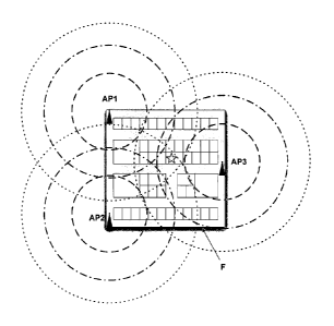
In some embodiments, with reference to FIGS. 4 and 5, an Access Point
Controller (APC) generates a series of tokens (e.g., random or pseudo-random)
and transmits them to a plurality of Access Points (AP) (which can be wireless
or
wireline connected to the APC). In FIGS. 4 and 5, three illustrative APs are
shown, AP1, AP2 and AP3. In some embodiments, each connected Access
Point (AP) receives a token and a set of parameters indicating the power with
which each token should be transmitted. A client device, signified in FIG. 5
by a
star shown in a particular office within the facility F, records the tokens it
hears
(e.g., which can be from a plurality of AOcess Points). Note: in some
embodiments, each single AP can be made to transmit a plurality of tokens,
with
each of the plurality of tokens being transmitted at different power levels so
as to
further assist in localization based on tokens received being representative
of
distance from a particular AP. For example, in some embodiments, as shown in
FIG. 5 with varied dashed line circles around the access points, the differing
concentric dashed-line circles can represent differing token transmission
regions.
At the end of the phase, the client informs the Access Point Controller
which tokens it has received. The APC compares these tokens against a list of
tokens that should have been received at each location and then determines the
corresponding general or macro location.
Pico-Localization
The foregoing Macro-Localization provides a general area for a client's
location. In some situations, one may need to know a more specific location
(such as, e.g., a specific office or room). According to some embodiments, the
APC re-launches the localization phase, but this time the APC receives (e.g.,
asks for) assistance from certain deployed hardware (such as, e.g., desktop
computers), which can be, e.g., distributed throughout the facility F (such
as, e.g.,
within particular offices in the facility).
19
CA 02693834 2010-01-13
WO 2009/011822
PCT/US2008/008586
In this regard, by way of example, desktop computers throughout a
particular office and/or throughout a facility, can be equipped with wireless
broadcasting capabilities, such as, e.g., U.S.B. 802.11 wireless cards. These
can be relatively inexpensive attachments (costing, e.g., less than about
$30.00
each) and can allow PCs to act essentially as local Access Points (APs). In
some embodiments, at a single low power, each PC (referred to herein as a
"Pico-AP") can broadcast a new set of tokens (e.g., pseudo-random tokens)
generated by the APC. In return, the client devices can then return the new
set
of tokens that it receives to the APC. Upon receiving the second token report,
the APC can determine a more exact location for each client.
Location Mapping Mode
Developing maps of wireless coverage for an area is time consuming
using traditional means. More importantly, wireless coverage is constantly
changing, so static representations are not realistic. It is, therefore,
important to
be able to dynamically generate accurate representations of coverage.
In the preferred embodiments, a mapping mode is provided ¨ e.g., an
automatic means of characterizing the coverage of each AP for a given
environment.
In some embodiments, the mapping mode is similar to the standard
operation of the localization tool. APs broadcast a series of tokens generated
by
the APC. The Pico-APs then report the tokens they hear back to the APC, which
compares these tokens against the ones it sent out. Over time, the APC can
develop, e.g., statistical maps of regions, such that it can anticipate with a
high
probability the tokens a client should hear.
Broad Scope of the Invention:
While illustrative embodiments of the invention have been described
herein, the present invention is not limited to the various preferred
embodiments
CA 02693834 2010-01-13
WO 2009/011822
PCT/US2008/008586
described herein, but includes any and all embodiments having equivalent
elements, modifications, omissions, combinations (e.g., of aspects across
various embodiments), adaptations and/or alterations as would be appreciated
by those in the art based on the present disclosure. The limitations in the
claims
are to be interpreted broadly based on the language employed in the claims and
not limited to examples described in the present specification or during the
prosecution of the application, which examples are to be construed as non-
exclusive. For example, in the present disclosure, the term "preferably" is
non-
exclusive and means "preferably, but not limited to." In this disclosure and
during
the prosecution of this application, means-plus-function or step-plus-function
limitations will only be employed where for a specific claim limitation all of
the
following conditions are present in that limitation: a) "means for" or "step
for" is
expressly recited; b) a corresponding function is expressly recited; and c)
structure, material or acts that support that structure are not recited. In
this
disclosure and during the prosecution of this application, the terminology
"present
invention" or "invention" may be used as a reference to one or more aspect
within
the present disclosure. The language present invention or invention should not
be improperly interpreted as an identification of criticality, should not be
improperly interpreted as applying across all aspects or embodiments (i.e., it
should be understood that the present invention has a number of aspects and
embodiments), and should not be improperly interpreted as limiting the scope
of
the application or claims. In this disclosure and during the prosecution of
this
application, the terminology "embodiment" can be used to describe any aspect,
feature, process or step, any combination thereof, and/or any portion thereof,
etc.
In some examples, various embodiments may include overlapping features. In
this disclosure, the following abbreviated terminology may be employed: "e.g."
which means "for example."
21