Note: Descriptions are shown in the official language in which they were submitted.
CA 02696658 2010-03-22
WO 02/25920 PCT/IL01/00388
-1-
Telephone communication system and method
over local area network wiring
FIELD OF THE INVENTION
The present invention relates to the field of common networks for data
communication and telephony, and, more specifically, to the networking of
telephone sets within a building over digitally oriented local area network
wiring, simultaneously with the data transmission.
BACKGROUND OF THE INVENTION
Small office and business environments commonly employ a
multiplicity of work cells, each equipped with a telephone set and a computer.
Two separate networlcs are usually employed for communication among the
cells and between them and the outside world - a telephone network,
connecting between the telephone sets and outside telephone lines, and a so-
called local area network (LAN), connecting the computers among themselves
and to outside networlc lines.
The term computer or personal computer will be understood to include a
workstation or other data terminal equipment (DTE) or at least one digital
device capable of inputting and outputting data, whereby each computer
includes an interface for connection to a local area network (LAN), used for
digital data transmissioii; any such device will also be referred to as a
remote
digital device. The term telephone set will be understood to include any
device
which can connect to a PSTN (Public Switched Telephone Networlc), using
telephony band signals, such as fax machine, automatic answering machine or
dial-up modeni; any such device will also be referred to as a remote- or local
telephone device.
CA 02696658 2010-03-22
WO 02/25920 PCT/IL01/00388
-2-
Such an environment is depicted in Figs. la and lb, which show a
typical small office/business configuration, requiring two separate and
independent networlcs. Fig. la shows a telephony network 10 comprising a
PABX (Private Automatic Branch Exchange) 11, connected via lines 12a, 12b,
12c and 12d to telephone devices 13a, 13b, 13c and 13d respectively. The
telephone are of the POTS (Plain Old Telephone Service) type, requiring each
of the connecting lines 12 to consist of a single pair of wires.
Fig. lb shows a local area networlc (LAN) 15 for allowing
communication between computers. Such a network comprises a hub (or
switching hub) 16, connected via lines 17a, 17b, 17c and 17d to computers
18a, 18b, 18c and 18d respectively. Popular types of LANs are based on the
IEEE802.3 Ethernet standard, using lOBaseT or 100BaseTX interfaces and
employing, for each connecting line 17, two twisted pairs of wires - one pair
for transmitting and one pair for receiving.
Installation and maintenance of two separate networks is complicated
and expensive. It would therefore be advantageous, especially in new
installations, to have a combined wiring network system that serves both
telephony and data communication requirements.
One approach is to provide a LAN only, which serves for normal inter-
computer communication, and make it seive also for telephony. One general
method for this approach, in common usage today, utilizes so-called Voice-
Over-Internet-Protocol (VoIP) techniques. By such techniques, known in the
art, telephone signals are digitized and carried as data in any existing LAN.
Systems employing such techniques are, however, complex and expensive, and
the quality of the voice carried by currently available technology is low.
Another, opposite approach is to utilize an existing telephone
infrastructure for simultaneously serving as both telephone and data
networking. In this way, the task of establishing a new local area network in
a
I
CA 02696658 2010-03-22
WO 02/25920 PCT/II..01/00388
-3-
home or other building is simplified, because there are no additional wires to
install.
U.S. Patent 4,766,402 to Crane teaches a way to form a LAN over two-
wire telephone lines, but without the telephone service.
The concept of frequency division multiplexing (FDM) is well-known in
the art, and provides a means of splitting the inherent bandwidth of a wire
into
a low-frequency band, capable of carrying an analog telephony signal, and a
high-frequency band, capable of carrying data or other signals. Such a
technique, sometimes referred to as `data over voice', is described, for
example, in U.S. Patents 5,896,443, 4,807,225, 5,960,066, 4,672,605,
5,930,340, 5,025,443 and 4,924,492. It is also widely used in xDSL systems,
primarily Asymmetric Digital Subscriber Loop (ADSL) systems.
A typical system employing FDM is illustrated in Fig. 2, which shows
schematically a combined telephony/data network 20, providing in this case
connections to two work cells by means of corresponding two cables 12a and
12b, each comprising a single twisted pair of wires. The lower part of the
spectrum of cable 12a is isolated by Low Pass Filters (LPF) 22a and 22b, each
connected to a respective end of the cable. Similarly, the higher part of the
spectrum is isolated by respective High Pass Filters (HPF) 21a and 21b. The
telephony network uses the lower spectrum part by connecting the telephone
13a and the PABX 11 to the respective LPFs. In order to use the higher part of
the spectrum for data communication, telephone-line modems 23a and 23b are
respectively connected to the HPFs 21a and 21b at both cable ends. Hub 16
connects to modem 23a, while, on the user side, modem 23b connects to
computer 18a, thus offering connectivity between the computer and the hub.
The spectrum of the other cable 12b is similarly split and cable 12b connects
telephone set 13b to PABX 11 via LPFs 22c and 22d, while computer 18b
connects to hub 16 via modem 23d, coupled to HPF 21d, and modem 23c,
coupled to HPF 21c. Additional telephones 13 and computers 18 can be added
I
CA 02696658 2010-03-22
-4-
in tb.e same manner. This prior-at concept is disclosed in U.S. Patent
4,785,448
to Reichert ed at. (hetebafter referred to as "Reichm') and U.S. Patent
5,841,841 to Dodds et al. (bereinafter xefanred to as "Dodds"). Both Reichert
and Dodds suggest a method nad apparatus for applying requency
doramainldivisioa multiplexiag (FDM) technique for residential teiepb.one
wixing, enabl:img simultaA.cously canymg teleptaone and data cmmumeatioa
siguals, as described above.
U.S. Patent 5,610,922 to Balatoni discloses a method and apparatus for
t+ranset-ring aaalog voice telephone, signals and digital data service
signals
a 0 simultmotisly from a telephone company location to a customer premises
over
a single tvvisted pair telephone line. The apparatus includes an easily
instaJled
voice plus digital data service remote tenubW and voice plus digM data
service central office teYminal. The apparatns can provide a 3 to-1 pair gain
by
multiplexing sigtasls represenzmg the analog voice telephone signals and 4-
wire
digital data service signals.
Network 20, employing an FDM method, typically requires two
modems (such as 23a and 23b in Pig. 2) for each conneCted cell. Suekt modems
are complex and expensive. In addition, the low coxnmunicatioa quality of a
typical telephone line, which was designed to carry low fxequency (telephony)
signals only, limits both the data rate and the distance of the data
cotntt-unication.
The concept of oztaing a phantom chatmel to serve as an additional path
ia a two wire-pairs commuuication system is known in the art of telephony, and
diselosed in several patents, classified under U.S. Class 370/200. Commonly,
snch a phsatom channel path is used to eany power to feed remote e:quipmeat
or intecmediate repeaters. In some prior-art systet'ns, exemplifted by U.S
Pateuts 4,173,714, 3,975,594, 3,806,814, 6,026,078 end 4,937,811, tb.e
pbantosn channel is used to carry ad.di.tionat sigaals, suah as metering and
other
auxiliary signals. Thus, all such systems use the phmtAm channel only as
Em v f a n g: AMENDED SHEET
CA 02696658 2010-03-22
-4a-
zneans for helping the communication service over the main ehameis. None of
the mentioned prior-art uses the phaztom cha,Qnez for carrying au additxoua]
communication type of service, or for fwxetiomally combining two distinct
networks.
It would thus be desirable to allow a dara networking system to
simultaneously also provide telephone service without any additional wiring.
SUNIMARX OF TSE INYZcN~,'ION
it is an object of the invention to allow a data networking sys= to
sirnultmeously also provide telephone service without aiy additional wizung.
This object is zealized in accordance wi.th a broad aspect of the invention
by a Gizcuit for use with a bundle containing at least two paixs of
conductors,
the circuiR comprisiug:
first connections for coupling to an end of said bundle;
second cozniections for coupling to at least one digital device; and
third connections for coupling to at least one telephone devxce;
characterized in that:
two of said cfucuits, coupled by respective ones of said 15rst counecf.ions
to opposite eiids of arespective pair of conductors in said bundle. cooperate
to
fortn at least one phautom chamel allowing for telephone commuaication
between, respective telephone devices connected at opposite ends thereof via
respective ones of the th,ixd conneotfons simul,taneous with digital
connnnmiica-
tion between resiaectlve digital devices each coupled at opposite ends of the
bundle ta'the second coymecia.ons of a respecti.ve one ofsai.d circuits.
Conventional data net^worlcs use a four-conductor aixeuit azrangement
providing two communication channels betwom two units. For example,! in a
local area network based on Efli=emet IOF3aseT or IOUSaseTX, two paiics of
conduetors are Employed between a hub and DTE such as a compuxer. By
rxiea,ns of the inventioxt, POTS connection, such as betweexL e.xchazzg ~ and
, =
EmpfanBsAMENDED SHEET
CA 02696658 2010-03-22
-5-
telcphone apparatus, is accomplished simultaneously over the same four
cojfductors used for the two commusucatioaa cbmels witiLOut interftence. The
POTS service commuaicatioa is accomplished via a phantom= circuit
a~xangement over the four conductors.
Such configuxation cau be employed within small office or small
busmess, whcrein single wiuang infradnu=tvre is used for distnbutin.g both
data
aad telephone signgs rom a cenbral location, including a hub and an exchange
to a remote statton, eazb such station comprising a telephone unit aod a data
unit (e.g. desktop computer).
The present invention provides a circuit arrangem.eut wherein a cable
that includes two twisted-conductor pairs provides both a two-way data
coanzta.unication cbannel for a cormected computer and, sisuultaaeauslq, a
path
for POTS signal to and from a connected telephone set, using the phaatom
chanael method. Jn the prefemd embodimeart, the data cooazxumicasion channel
consists of aa Ethetnet IEEE802.3 LAN chvoaael and lOBaseT, or 100BaseTX
interfaces.
According to a speoi.f c embodi,uent of the invention, each two-
conductor patz is terminated at each of its eaads with a ceptcr tapped
prma,axY
traasfozmer wind'ug (hr,reinaftcr cabte-side wiuding), wk-ereby each conductor
of the pair is connected to a respective end of the cable side winding. Each
vvinding is inductively coupl,ed to a secondary winding (hereinafter refened
to
as equipment side winding), whose ends are connected to another pair of
coaductoxs that form the continuation channel for the data carrying signal,
wherei~~, the equipmant side winding is conmcteid to the data conzmmzcataon
equipment. The cenctez taps of each of the two primary winding at any emd of
the cable are connectable to the respective comductors of a telephone circuit,
to
catiy tbs PO'fS sigmals. Thus, the two pairs of conductars at opposite ends of
the cable, thxough the cxnter taps of the respecdve prtmary transfat=mer
Es p f a n e s AMENDED SHEET
CA 02696658 2010-03-22
`^--
-6-
windings, form first and second comaectxcros of the two conductor phantom
channeL which is used for carrying tlxe telephone signal.
The iuvesttion can be implemented by means of two modules each
containmiug a respective circuit - one at each end of the two--conductor-pairs
cable. Each eioccuit comprises two transformers, with a center-tap in the
pdmary
(cable side) winding. The module xetains the two-pair data commuaicati.on
capability, while simultaneously including a phantom channel vi. . the eenter-
tapconnections, for teleph.one service. The phantom chamet can be accessed
via a comnector in the.module. The module can be a stand-alome unit, or
integrated wrthin any unit in the network, such as a digitaJ, n.etwork hub, a
telephone excbange, a server computer or telephone set. ,A,iternatively, the
module can be ixstegrated within a wall outiet connected to one or both ends
of
the cable.
in sm,otb,er embodiment, the modules form a lcxt, which is. used to
upgade an existing local area aetwork to support tetephone networking also.
The invention can be used in a sarall office or small business
en,vironzn.ent, whi,cb has a central locatfon that comprises a telephone
exchsnge
and a digital network eoncentration unit (such as a hub, a switch or a
router),
comected to multiple remote work stadoos via LAN wiring.
$EM,,T DESCRII''ITaN O =DRAWINraS
in order to understaud the invention and to see how it may be carried out
in= practice, a preferred embodiment wili now be described, by way of nozk-
lixu,iting example only, with refereace to the accompaoying drawius.gs, in
whicb:
Figs. 1+a and lb show respectively a commom prior art telephone and
Local Area Network conf.gluataioa as used within a small office or a small
busxriess;
Fig. 2 shows a prior art telephone and local am networks using the
telephone-wiring infixastructnre;
= ~
EWanss AMENDED SHEET
CA 02696658 2010-03-22
_7_
Fig. 3 shows a combinad telephome and data. oommunimtaon network :
according to the pzeseat invention;
Fig. 4 shows schematically a data comt.ntmications network havimg
mulZiple phantom- chann.els according to the present invention all sharing a
comtnon retum;
Fig. S$ shows schematically a computer modit.ed a.ccording to the invention
for direct coupling to a telephouE set;
Fig. 5b shows sel3ematica.lly a telephone set modlfked according to the
invention for dixeet coupling to a c4cttputer,
Fig. 6 shows modified wall outlet tltat adds a phantom chanra,el
telephone service to an exastmg data cotaawmcaUon system according to the =
prwent invenfiion; and
Figs. 7a to 7d show different views of an al.tachable wall plug connector
that adds a phantarm cbaxnael telephone service to eu exlstiau.g data communi-
cation Mtein accoxdian.g to the presoat iumo.tUion.
DLTAYLED AESC1tIPT1ON OF THE INVENTION
In the oHowing description it is to be noted that the drawings sud
descripaons are conceptW only. In acttzal practice, a sin.gle component can
implement one or more functions; alternatively, each function can be
implemented by a plurality of components and circuits. In the drawings and
descriptions, identical reference numerals are use to in.dicate those
components
that are common to different ecnbodiqmeots or configvrations.
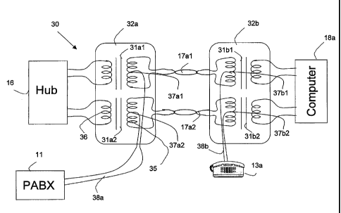
Fie, 3 illvsbrates a pr.ef'arred embodiment of the present invention. The
network 30 is a paxt of an LEEE802.3 local area nAtwork, using LOBaseT
interfaces. A hub 16, defining a central location. is connected to a iypxcal
computer 1Sa via a cable that includes two wire pairs 1741 aad 174. Each pair
is operPtav'e tv carry data in one direction only, one pair, say 17a1,
can3+ing .
data from the hub 16 to the computer 18a, whiZe t}.Le other pair, 17a2, cmies
Empfann AMENDED SHEET
CA 02696658 2010-03-22
-$-
data in tbc otlaer direction. rig. 3 also shows a telepb.one set 13a,
associated
with computer Xga and preferably near it. and a telephone private automatic
branch exchange (PABX) 11, which is preferably also at the central location.
The terna hub is used herein to represent any digital network concentrating
unit
sad may equally refer to a switching hub, a xoma. a server computer or to any
digital device havimg multiple data ports; any of these being also referred to
herein as a central digital device. SibOaxly, PAi3X is used herein to
represent
any type of central telepbone switching unit and wiII also be referred to as a
central telephone device.
According to the mvention, a signal trfuxsformer is inserted at each end
of each wire pair, whereby, for example, transfornaer 31a1 is inserted at the
end
owire pair 17a;i that is near hub 16 and transfotmer 3l.bX is iunserted at
the end
of wire pair 17al tb.at is near computer. iSa. Similarly, trmfonmrs 31a2 and
M2 are in.serted at the ends of wire pair 17a2 that are near hub 16 and
computer.l8a, respectively. The sigmW transformers bearing the prefix 31 are
designed so ftt the signal attenuation vi.a. these transformers is
negligitbl.e.
Hence, the performance of the data communication networlc is fully retained,
and the hub 16 continues to communicate fully with the computer 1$a in the
usual manner. Such tramforiners are kaown in the art and are often used in
2o LANs, in order to meet isolation and common-mode rejection xequaz~ooemts. .
Commonly, such signal urausformers are equipped with a primary winding and
a secorLdary winding both being untapped coils. laa the invention, each signal
transformer bearing the prefix 31, say 31a2 has a primary winding 35, whose
eAds are connected to the respective wires of the cabae, and a secondary
winding 36, whose ends are connected to the respective system. component
(hub.1.6 or computer 18a).
However, ux-like the converxd.ona.l confxgjuation for signax transformers,
according to the present invention each primary wiun.dimg 35 has a center-tap
sltown as 37al and 374, for the two signal t7ransformers 31a1 and 31.a2,
~ =
EmofanesAMENDED SHEET
CA 02696658 2010-03-22
-9-
respectively. Tlie ends of the primary windings 35 constitute first
connec.tions
of a circuit comprising the two the two signai traasfoxmears 31ai and 31a2 and
serve for coupling to respective pairs of con.ductrns in the bundle. The ends
of
the secondary windings 36 constitute second coanections for coupling to at
4east one digital device such as 16 or 18; and the center=taps 37a1 and 37a2
serve as tliird connections for coupling to at least one telephone device such
as
11 or 13. Thus, PA}3X 11 is coonected, via two respeclive wixes 38a, to the
ccntar taps 37al and 37a2 of txaosforrnners 31a1 and 31a2. Similarly, the
telephone set 13a is connected, via two =xespective wires 38b, to tla.e center-
taps
37b1 and 37b2 of transformers 31b1 aad 31b2, respectively. In this
configuratirnn, the telephony signals are carried in $`phantom' way together
with the data cammunicaxion signals, without any iuatcrfarence between the
two. Tin practice, the hub side transfornaers 31a1 and 31a2 may be imtegrated
to
form a module 32a, while the computer side transfozmers 31b1 and 31b2 may
be iitegrated to form a u1odul.e 32b. Wbdle the network 30 has so far been
EaPfanBsAMENDED SHEET
CA 02696658 2010-03-22
-- ^~
WO 02/25920 PCT/II.01/00388
-10-
described as supporting a single computer and a single telephone, additional
worlc cells, each comprising a telephone and a computer can be supported,
whereby each computer is connected with hub 16 through a corresponding two
wire pairs cable, by inserting an additional set of modules 32a and 32b in
each
such cable.
While the invention has been described specifically for 10BaseT
(lOMb/s) interfaces, the invention can be equally applied to 100BaseTX
(100Mb/s) interfaces. Furthermore, the invention can be equally applied in any
wired networking system using at least two wire pairs. Transformers can be
used in all wired communication systems whose signals do not include direct
current (DC) components. In systems that use four or more pairs of wires, such
as those based on the evolving 1000BaseTX Ethernet standard, each two pairs
can be used to form a single phantom channel. Thus, four pairs can form two
phantom channels, each carrying one POTS circuit, by terminating each pair
with a transformer as described above. Alternatively and preferably, as shown
in Fig. 4, three pairs 17a1, 17a2 and 17a3 can each form a phantom channel
with the fourth pair 17a4, which serves as the common return path. In this
case,
each telephone circuit 13a, 13b and 13c has one of its two wires connected to
the center-tap 37b1, 37b2 and 37b3 of the respective transformer 31b1, 31b2
and 31b3 at the corresponding end of the respective pair and the other wire -
to
the center-tap 37b4 of the transformer 31b4 at the corresponding end of the
common pair. More generally, with N pairs of conductors, each pair serving as
a data channel, it is possible to similarly provide N-1 phantom channels for
telephone service.
In the configuration shown in Fig. 3 the modules 32a and 32b are stand-
alone modules, mechanically separate from other components in the network.
However, also other configurations are possible. For example, the hub side
module 32a can be integrated, fully or in part, within the hub 16. In such a
case, the hub's existing data connection-unit (such as a distribution frame -
for
I
CA 02696658 2010-03-22
WO 02/25920 PCT/1L01/00388
-11-
connecting thereto all line pairs) is preferably substituted by one that
includes
module 32a; in addition, a telephone connector is provided, for connecting all
telephone lines (whose other ends are connected to their respective center
taps
in module 32a) to the PABX. Alternatively, module 32a can be siniilarly
integrated within PABX 11, whereby an appropriate connection with the hub is
provided.
Fig. 5a shows schematically an arrangement where the computer side
module 32b is integrated, fully or in part, within the computer 18a. Thus, the
secondary windings 36 of the transformers 31a1 and 31a2 are connected to
receiver and transmitter circuitry 39a and 39b within the computer 18a. The
ends of the primary windings 35 of the transformers 31a1 and 31a2 are
connected to a standard socket outlet 40 for connecting to the network. The
center-taps 37a1 and 37a2 are connected to a standard telephone outlet 41,
enabling connection thereto of a telephone set such as designated 13a in Fig.
3.
Fig. 5b shows schematically the complementary arrangement where the
module 32b is integrated the telephone set 13a. Thus, the secondary windings
36 of the transformers 31a1 and 31a2 are connected to a standard outlet 42 for
connecting thereto a computer such as designated 18a in Fig. 3. The ends of
the
primary windings 35 of the transformers 31a1 and 31a2 are connected to a
standard socket outlet 43 for connecting to the network. The center-taps 37a1
and 37a2 are connected to telephone circuitry 44, within the telephone set
13a.
Alternatively, the computer side module 32b can be integrated within a
wall connector allowing direct or indirect connection to an existing wall
socket
outlet. Thus, such a wall connector can be constituted by a substitute wall
socket having integrated therein a pair of signal transformers and two female
outlets for connecting a computer and telephone thereto, respectively.
Alternatively, the wall connector can be constituted by a plug connector
having
integrated therein a pair of signal transformers and two female outlets for
connecting a computer and telephone thereto, respectively. Such a plug
I
CA 02696658 2010-03-22
WO 02/25920 PCT/II.01/00388
-12-
connector allows a computer and telephone to be connected to an existing wall
socket outlet without requiring any modification thereto.
Fig. 6 shows the faceplate of a modified socket outlet 45 according to
the invention. Two conductor pairs are connected to the outlet at the rear
(not
shown in the Figure), connected to the primary windings of two signals
transformers housed in it (not shown in the Figure). The secondary windings of
the transformers are connected to RJ-45 data connector 46, while the center
taps are connected to the RJ-11 telephony connector 47. Such an outlet is
physically similar in size, shape, and overall appearance to a standard
outlet, so
that such an outlet can be substituted for a standard outlet in the building
wall.
No changes are required in the overall LAN line layout or configuration. Such
an outlet can easily substitute an existing standard data outlet to thus
additionally provide telephony support. Thus a conventional outlet has a
single
female connector having two pairs of wiper contacts connected to the
respective twisted-wire pairs for data transmission and reception. A computer
is
plugged into such a conventional outlet via a single male connector (plug)
having four pins: two for handling data transmission and two for handling data
reception. On inserting the plug into the socket outlets, the pins brush
against
the wiper contacts in the socket outlet, thus establishing electrical
connection
between the two.
The invention allows for the conventional outlet to be replaced by a
modified outlet having therein a pair of signal transformers, the ends of
whose
respective primary windings are adapted to be connected to the ends of a
respective conductor pair in the network. The secondary winding of each signal
transformer is connected internally to a respective pair of wiper contacts of
a
first female connector. Thus, the ends of both secondary windings are
connected to first female connector by means of four wiper contacts in total.
The respective center-taps of each of the two primary windings are connected
to a pair of wiper contacts in a second female connector proximate the first
I
CA 02696658 2010-03-22
WO 02/25920 PCT/II01/00388
-13-
female connector. Thus, a computer can be connected, via four pins of a
suitable jack plug, to the first female connector, while a telephone can be
connected, via two pins of a suitable jack plug to the second female
connector.
The two wire pairs 17a1 and 17a2 are routed and connected to such an outlet,
which will now comprise two faceplate connectors - a data connector (e.g. RJ-
45 for lOBaseT) and a telephone connector (e.g. RJ-11).
Such an implementation requires that the soclcet outlets in an existing
data network be replaced by a modified outlet according to the invention.
Figs.
7a to 7d show various views of a plug assembly 50 according to the invention
for operation in lOBaseT or 100BaseTX environment that allows the invention
to be implemented without requiring any modification to the data network or to
the existing socket outlet. In use, the plug assembly 50 is plugged into a
standard soclcet outlet and is retained therein by means of a latch 51. The
plug
assembly 50 contains the module 32b connected to separate data- and
telephony socket outlets 52 and 53 in a similar manner to the modified socket
outlet 45 described above with reference to Fig. 6. A standard RJ45 jack plug
54 is connected to the module 32b for mating with the wall outlet when
plugged into its socket. The jack plug 54 thus includes two pairs of pins each
connected to the primary winding of a respective signal transformer within the
module 32b. The secondary windings of the two signal transformers are
connected to respective wiper contacts in the data-telephony soclcet outlet
52.
The respective center-taps of each of the primary windings are connected to a
pair of wiper contacts in the telephony socket outlet 53 proximate the data-
telephony socket outlet 52. Cables from the computer and the telephone set
terminate in standard jack plugs that are plugged into the respective data-
and
telephony socket outlets 52 and 53 within the plug assembly 50. Thus, the plug
assembly 50 obviates the need for any changes to be made to the existing
infrastructure.
CA 02696658 2010-03-22
WO 02/25920 PCT/II.01/00388
-14-
As mentioned above, lOBaseT and 100BaseTX interfaces, as well as
other data communication interfaces, often include signal transformers in the
line connection circuitry, in order to meet isolation and common-mode
rejection requirements. In such cases, additional transformers, though
possible,
are not required and the method of the present invention can be implemented
by adding center-tap connections to the respective windings of the existing
transformers and using them to form a phantom channel, to serve for telephone
connection in the manner described above. Alternatively, the existing
transformers can be substituted by ones with center-taps as specified above.
It is noted that, while a phantom channel has been known in the art, its
use in the system and method disclosed herein is novel, because:
(a) Local area networks (LANs) in general, and Ethernet networks in
particular, currently do not employ phantom channels, nor is any configuration
employing such channels specified in the IEEE802.3 standards; the concept is
known in the realm of telephony only, which is very different from that of
data
communication LANs.
(b) Using a phantom channel itself to carry POTS service is not known
in the art; rather, phantom channels are used only to carry power to remote
units and/or management- or control signals to support the main service that
is
provided by the two conductor pairs.
While the invention is described above relating to hub units, it is clear
that any other multi-port data communication device can be used, such as
switch, router or gateway.
The present invention also embraces a method for upgrading an existing
local area network (LAN) installation that includes a two-conductor pair cable
between two digital devices, to also and simultaneously convey signals
between two telephone devices, the method comprising:
(a) inserting a first pair of signal transformers having center-tapped
primary windings at a first end of the cable, with respective ends of
I
CA 02696658 2010-03-22
WO 02/25920 PCT/IL01/00388
-15-
the primary windings connected to respective conductors of the
cable; and
(b) inserting a second pair of signal transformers having center-tapped
primary windings at a second end of the cable, with respective ends
of the primaiy windings connected to respective conductors of the
cable;
thereby allowing respective secondary windings of each signal
transformer to be connected to the digital devices and allowing the respective
center-taps of the signal transformers to be connected to telephone equipment.
If the LAN already includes signal transformers that do not have center-
taps, they are, in step (a) above, replaced by the specified transformers or,
alternatively, a center-tap is added to each primary winding.
While the invention has been described with respect to a limited number
of embodiments, it will be appreciated that many variations, modifications and
other applications of the invention may be made.