Note: Descriptions are shown in the official language in which they were submitted.
CA 02702997 2010-04-19
WO 2009/049397 PCT/CA2007/001874
TITLE: Heat management device using inorganic foam
FIELD OF THE INVENTION
The present invention relates to heat management
devices such as a heat pipe that uses a component made of
inorganic porous material. The heat pipe can be used to
provide cooling in a wide range of applications through
repeated evaporation and condensation cycles of a working
liquid. In one specific example the heat pipe can be used
to provide cooling to electronic devices such as Central
Processing Units (CPUs). The invention also extends to a
method for making metallic porous material and to the
resulting product thereof.
BACKGROUND OF THE INVENTION
Many different applications exist, in particular in the
electronics industry where components need to be cooled such
as to maintain them within a temperature range in which they
can reliably operate. An example of a cooling device that
has found wide acceptance is the heat pipe. A heat pipe is
capable of transferring thermal energy very effectively
allowing to maintain the surface of an electronic component,
such as a CPU, relatively cool.
A typical heat pipe has a closed chamber with a hot
side and a cold side. The hot side is the side that
receives the heat to be removed while the cold side
transfers that heat to an adjoining medium acting as a heat
sink. Working fluid, such as water is provided in the
closed chamber. When the hot side receives thermal energy,
that energy vaporizes the working fluid that is in the
vicinity of the hot side. The vapor naturally flows in the
chamber to the cold side where it condenses. The latent heat
1
CA 02702997 2010-04-19
WO 2009/049397 PCT/CA2007/001874
of vaporization that is released during the condensation
process is transmitted to the cold side and to the adjoining
medium. A wick is provided between the cold and the hot
sides such that condensed liquid is continuously supplied to
the hot side where it can be vaporized again.
The wick can be made from sintered metallic material
that owing to its porous structure pulls the liquid by
capillary action toward the hot side. Alternative
arrangements can also be used such as an array of fine
channels machined on the bottom wall of the chamber that
also develop capillary pressure capable of transporting the
working liquid.
As an alternative to the wick, the geometry and
orientation of the heat pipe may be such that liquid is
allowed to flow back to the hot side by gravity. In such
case, a wick structure to transport the liquid may not be
required.
The continuous phase change cycle of the working liquid
from liquid to vapor and then back to liquid confers a very
good heat transport characteristics to the heat pipe.
Depending on the design and configuration of the heat pipe,
a number of factors determine the ultimate heat transport
capacity. The key factors are (1) the ability of the
structure to allow the vaporized liquid to escape from the
boiling liquid and (2) the ability to supply continuously
sufficient amounts of working liquid to the hot side for the
evaporation to be maintained. If any one of these two
mechanisms is interrupted the heat transport cycle stops and
in the case of key factor (1) the heat pipe reaches the so
called critical heat flux value and in case of key factor
(2) the heat pipe reaches the so called dry out state. At
2
CA 02702997 2010-04-19
WO 2009/049397 PCT/CA2007/001874
the critical heat flux value water vapor is essentially
trapped under the pool of working liquid and the heat pipe
essentially ceases to function. In the dry out state, there
is no more working liquid to be evaporated and the heat pipe
essentially ceases to function.
While current heat pipe designs are effective, there is
a need in the industry to raise their heat transport
effectiveness even further such as to allow the heat pipes
to be made smaller and/or capable of handling more intense
cooling requirements.
SUMMARY OF THE INVENTION
As embodied and broadly described herein the invention
provides a heat pipe having an enclosed chamber with a hot
side and a cold side and an inorganic porous structure
between the hot side and the cold side. The inorganic
porous structure transports working liquid by capillary
action from the cold side toward the hot side and having a
wicking speed in excess of about 0.005m/s.
As embodied and broadly described herein the invention
provides a heat pipe having an enclosed chamber with a hot
side and a cold side and an inorganic porous structure
between the hot side and the cold side. The inorganic
porous structure transports working liquid by capillary
action from the cold side toward the hot side and having
an absorption capacity of at least 200kg/m3.
As embodied and broadly described herein the invention
provides a heat pipe having an enclosed chamber with a hot
side and a cold side. The heat pipe also has an inorganic
porous structure between the hot side and the cold side
3
CA 02702997 2010-04-19
WO 2009/049397 PCT/CA2007/001874
for transporting working liquid by capillary action from
the cold side toward the hot side, the inorganic porous
structure having a porosity distribution, characterized
by:
i) a first pore group:
(1) having an average pore size in the
range from about 200pm to about 1000pm;
(2) having a pore size standard deviation
in the range from about 100pm to about 500pm
(3) constituting in the range from about
30% to about 80% of the void volume of the
inorganic porous structure;
ii) a second pore group having:
(1) having an average pore size in the
range from about 40pm to about 120pm;
(2) having a pore size standard deviation
in the range from about 30pm to 80pm;
(3) constituting at least 20% of the void
volume of the metallic porous structure;
iii) a third pore group:
(1) having an average pore size in the
range from about 250nm to about 20pm;
(2) having a pore size standard deviation
in the range from about 200nm to 10pm;
(3) constituting in the range from about
10% of to about 40% the void volume of the
metallic porous structure.
As embodied and broadly described herein the invention
provides a heat pipe having an enclosed chamber having a
hot side and a cold side. An inorganic porous structure
is provided between the hot side and the cold side for
transporting working liquid by capillary action from the
4
CA 02702997 2010-04-19
WO 2009/049397 PCT/CA2007/001874
cold side toward the hot side. The inorganic porous
structure has a porosity distribution, characterized by:
i) a first pore group:
(1) having an average pore size in the
range from about 20pm to about 200pm;
(2) having a pore size standard deviation
in the range from about 10pm to about 100pm
(3) constituting in the range from about
50% to about 80% of the void volume of the
inorganic porous structure;
ii) a second pore group:
(1) having an average pore size in the
range from about 250nm to about 15pm;
(2) having a pore size standard deviation
in the range from about 200nm to 10pm;
(3) constituting in the range from about
20% of to about 50% the void volume of the
metallic porous structure.
As embodied and broadly described herein the invention
provides a heat pipe having an enclosed chamber with a hot
side and a cold side and an inorganic porous structure for
receiving working fluid that is evaporated on the hot side
and condensed on the cold side. The inorganic porous
structure having a specific surface area in the range from
about 10,000 m2/m3 to about 100, 000 m2/m3.
As embodied and broadly described herein the invention
provides a heat pipe having an enclosed chamber with a hot
side and a cold side, at least a portion of the enclosed
chamber defining a conduit for conveying working fluid.
The conduit has a direction of longitudinal extent and
having walls defining in cross section a figure having a
5
CA 02702997 2010-04-19
WO 2009/049397 PCT/CA2007/001874
closed boundary. An insert made of inorganic porous
material is provided within the conduit, the insert being
in contact with the wall and in cross-section having a
shape that follows a shape of the wall at least along a
portion thereof.
As embodied and broadly described herein the invention
provides a process for manufacturing a component for use in
a heat management device, the process comprising:
a) providing a sheet of heat conductive material having:
iii) a pair of generally opposite main faces;
iv) a pair of opposite edge portions;
b) placing on one of the main faces a body of inorganic
porous material;
c) rolling the sheet into a tube while the body of
metallic material is located on the one of the main
faces, the rolling bringing the opposite edge
portions in a face-to-face relationship;
d) joining the opposite edge portions.
As embodied and broadly described herein the invention
provides a heat pipe having an enclosed chamber having a
hot side and a cold side. The heat pipe also having:
a) working fluid in the enclosed chamber;
b) an inorganic porous structure for receiving thermal
energy input at the hot side and for boiling the
working fluid, the inorganic porous structure:
i) having a porosity distribution, characterized
by:
(1) a first pore group having an average pore
size in excess of about 20pm;
(2) a second pore group having:
(a) having an average pore size in the range
from about 250nm to less than about 15pm;
6
CA 02702997 2010-04-19
WO 2009/049397 PCT/CA2007/001874
(b) having a pore size standard deviation in
the range from about 200nm to about 10 pm;
(c) constituting in the range from about 20% to
about 50% of the void volume of the inorganic
porous structure;
ii) having at least one main surface including a
plurality of projections.
As embodied and broadly described herein the invention
provides a heat pipe having an enclosed chamber having a
hot side and a cold side. The heat pipe also having:
a) working fluid in the enclosed chamber;
b) an inorganic porous structure for receiving thermal
energy input at the hot side and for boiling the
working fluid, the inorganic porous structure having:
i) a base layer;
ii) a plurality of projections extending from the
base layer and being integrally formed with the
base layer, the projections being spaced apart and
defining valleys therebetween;
iii) the projections and the base layer being porous;
iv) the pores in the projections having an average
pore size that is larger than an average pore size
of portions of the base layer that register with
the valleys.
As embodied and broadly described herein the invention
provides a method for manufacturing a metallic porous
structure for boiling working fluid in a heat pipe, the
method including providing a metallic porous blank having
a pair of main faces opposite to one another and embossing
one of the main faces to create a plurality of spaced
apart projections.
7
CA 02702997 2010-04-19
WO 2009/049397 PCT/CA2007/001874
As embodied and broadly described herein, the invention
further includes method for making an open cell porous
body, the method comprising the steps of:
a. providing a dry flowable powder mixture comprising:
i. a first predetermined amount of inorganic
particles having a first melting temperature;
ii. a second predetermined amount of a binding
agent having a decomposition temperature, the
decomposition temperature being lower than the
first melting temperature;
b. heating the mixture at a temperature lower than the
decomposition temperature to solidify or cure the
binding agent to obtain a solid continuous mixture;
and
c. heating the solid continuous mixture at the
decomposition temperature to decompose cleanly the
binding agent and obtain an non-sintered open cell
porous body; and
d. heating the non-sintered open cell porous body at a
temperature lower than the first melting
temperature to sinter the inorganic particles and
obtain a solid low density open cell porous body.
As embodied and broadly described herein, the invention further
provides a dry flowable powder mixture for making open cell
porous bodies. The mixture comprising a first
predetermined amount of inorganic particles having a first
melting temperature and a second predetermined amount of a
binding agent having a decomposition temperature, the
decomposition temperature being lower than the first
melting temperature.
BRIEF DESCRIPTION OF THE DRAWINGS
A detailed description of examples of implementation
of the present invention is provided hereinbelow with
8
CA 02702997 2010-04-19
WO 2009/049397 PCT/CA2007/001874
reference to the following drawings, in which:
Figure 1 a longitudinal cross-sectional view of heat
pipe constructed according to a non-limiting example of
implementation of the invention;
Figure 2 a transverse cross-sectional view of the
heat pipe of the example shown in Figure 1;
Figure 3 is cross-sectional view of a heat-pipe
according to another non-limiting example of
implementation of the invention;
Figure 4 illustrates a flat sheet of metallic porous
material for use in making the wicking structure of a heat
pipe;
Figure 5 shows the flat sheet of the metallic porous
material of Figure 4 formed into a tube for insertion in a
heat pipe;
Figure 6 shows the rolled tube of metallic porous
material placed inside a heat pipe;
Figure 7 shows a flat sheet including several layers
for use in making a heat pipe;
Figure 8 illustrates the tube structure obtained by
rolling the flat sheet of Figure 7;
Figure 9 is a cross-sectional shape of a heat pipe
according to yet another non-limiting example of
implementation of the invention;
9
CA 02702997 2010-04-19
WO 2009/049397 PCT/CA2007/001874
Figure 10 is perspective view of the heat pipe shown
in Figure 9, some elements being shown only partially to
expose underlying structures;
Figure 11 is a perspective view of a metallic porous
structure for use in boiling working liquid in a heat
pipe;
Figure 12 is an enlarged cross-sectional view of the
metallic porous structure shown in Figure 11; and
Figure 13 illustrates in cross-section yet another
non-limiting example of implementation of a heat pipe;
In the drawings, embodiments of the invention are
illustrated by way of example. It is to be expressly
understood that the description and drawings are only for
purposes of illustration and as an aid to understanding,
and are not intended to be a definition of the limits of
the invention.
DETAILED DESCRIPTION
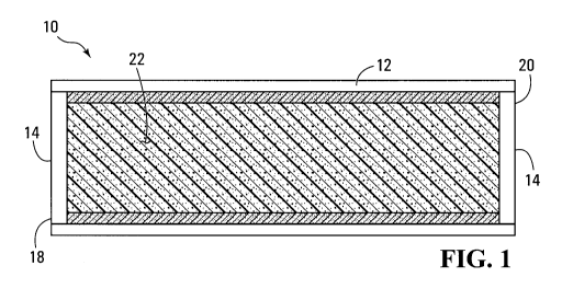
Figure 1 is a longitudinal cross-sectional view of a
heat pipe, according to a non-limiting example of
implementation of the invention. The heat pipe 10 is used
to provide cooling to a heat generating component (not
shown). Typically, such a component is an electronic
component such as a Central Processing Unit (CPU). Heat
pipes are effective cooling devices since they rely on the
vaporization and condensation of a working fluid, as a
heat transport vehicle.
CA 02702997 2010-04-19
WO 2009/049397 PCT/CA2007/001874
The heat pipe 10 has an enclosed chamber 12, which in
this example is in the form of an elongated cylinder. The
enclosed chamber has, therefore cylindrical walls closed
by end caps 14. Inside the enclosed chamber 12 is
provided a wick structure in the form of tubular liner 16.
The tubular liner 16 is an inorganic porous structure that
will be described in greater detail later. As shown in
the drawings, the tubular liner 16 extends almost the full
length of the heat pipe. It should be expressly noted
that this is merely an example of implementation and many
variations as to the placement, structure, shape and size
of the wick structure are possible.
The heat pipe 12 contains working fluid. The working
fluid is capable to accumulate thermal energy by
undergoing phase transition (from liquid to vapor) and
then releases that energy to an external medium. The
energy release causes the vapor to condensate. This cycle
repeats itself as long as there is heat to dissipate.
The heat pipe 12 has a hot section at which the
thermal energy is received and a cold section from which
the thermal energy is dissipated. The hot section and the
cold section can be located on any area of the heat pipe
structure 12 as long as they are sufficiently spaced apart
to allow the phase transitions in the working liquid to
take place. For instance the hot section can be
designated as the end portion 18 while the cold section
can be designated as the end portion 20. Thus, the hot
section 18 will, in use be in contact with the component
to be cooled, while the cold section 20 will release heat
to the surrounding medium. This surrounding medium may be
air, water or any other suitable material that acts as a
heat sink. To provide a more efficient heat release from
11
CA 02702997 2010-04-19
WO 2009/049397 PCT/CA2007/001874
the cold side 20, the cold side 20 may be provided with
any suitable heat dissipation structure such as fins, for
instance (not shown in the drawings).
The heat pipe 12 contains working fluid. That fluid
is in a liquid phase in the area of the hot section 18.
As a result of heat received at the hot section 18 the
working liquid boils and converts to vapor, the phase
change storing a significant amount of thermal energy.
The working vapor is allowed to flow toward the cold
section 20 via the lumen of the tubular liner 16. As the
vapor reaches the cold section 20 it condensed and
released heat to the surrounding medium. The condensation
effect reduces the vapor pressure in the cold section 20
and as a result creates a lower pressure which has the
effect of pulling vapor near the hot section 18 toward the
cold section 20. Accordingly, the boiling and the
condensation of the working fluid creates a pressure
gradient in the heat pipe 12 that naturally causes the
vapor to flow from the hot section 18 toward the cold
section 20.
The vapor condensed into liquid at the cold section
20 at the surface or to some limited depth within the
tubular liner 16. As indicated previously, the tubular
liner 16 is a porous structure. The porous structure that
will be discussed in greater detail later defines a
certain void volume within the "solid" area of the tubular
liner 16 (the lumen 22 is not considered to be part of the
solid area) . The void volume is capable to take-up the
condensed liquid and to carry that liquid toward the hot
section 18. The liquid transport is the result of
capillary pressure in the porous structure. Since the
liquid in the tubular liner 16 is boiled out at the hot
12
CA 02702997 2010-04-19
WO 2009/049397 PCT/CA2007/001874
section 18, the void volume or pores in that area are dry.
Accordingly, they pull by capillarity the liquid that is
building up in the porous structure near the cold section
20. Accordingly, the liquid migrates from the cold section
20 to the hot section 18, in a direction opposite the flow
of vapor, such as to sustain the phase transitions of the
working fluid.
Gravity also has an effect over the movement of the
liquid in the heat pipe 12. In the example shown in
Figure 1, where the flow path of the liquid is horizontal,
the gravity effect is largely minimized. In this case,
gravity only creates a non-uniform liquid loading of the
tubular liner 16, where more liquid will tend to
accumulate in the lower part of the tubular liner 16 than
in the upper part. However, this non-uniformity is also
dependent on the actual pore size and the attendant
capillary pressure exerted on the liquid. When the pore
sizes are relatively small, the capillary pressure is
higher and can counterbalance the gravity effect.
Accordingly, smaller pore sizes of the tubular liner will
tend to favor a more uniform liquid distribution (in a
vertical plane) in the tubular liner 16.
Gravity will have a more pronounced effect when the
geometry of the heat pipe 12 is such that the hot section
18 is at a different elevation than the cold section 20
(not shown in the drawings) . For example, if the cold
section 20 is located at a higher elevation than the hot
section 18, then gravity will assist the movement of
working liquid toward the hot section 18. In contrast,
when the cold section is located at a lower elevation than
the hot section 18, then the capillary effect will have to
combat gravity in order to transport the liquid toward the
13
CA 02702997 2010-04-19
WO 2009/049397 PCT/CA2007/001874
hot section 18.
The amount and type of working liquid in the heat
pipe 12 will vary according to the intended application.
Since the heat transport mechanism is based on phase
transition, it is not necessary to form in the heat pipe
12 a pool of liquid that will submerge a portion of the
tubular liner 16. It is usually sufficient to provide
enough liquid such as to create within the tubular liner a
continuum of liquid that extends from the cold section 20
to the hot section 18. As to the type of working liquid
used, it depends on the temperature range within which the
cooling is to be provided and also the compatibility of
the liquid and the materials used to make the heat pipe
12, including the tubular liner 16. In one specific
example, the working liquid is water and the enclosed
chamber 12 and the tubular liner 16 are both made of
copper. Other possibilities exist. In operating
temperature under water's freezing point, ammonia (NH3) is
used as the working liquid and nickel as the constituting
material for the enclosed chamber 12 and the tubular liner
16.
The tubular liner 16 is bonded to the inner wall of
the enclosed chamber 12 in order to provide a good thermal
conductivity. Such thermal conductivity is important to
allow heat to easily enter the hot section 18 and boil the
liquid and also easily egress the cold section 20. Good
thermal conductivity is created by forming an intimate
physical contact between the tubular liner 16 and the
inner wall of the enclosed chamber 12. Examples of
bonding techniques which would work well when the tubular
liner 16 is made of metal and that would provide an
intimate physical contact include sintering or soldering
14
CA 02702997 2010-04-19
WO 2009/049397 PCT/CA2007/001874
connections between the tubular liner 16 and the enclosed
chamber 12.
Soldering is a bonding process whereby a filler metal
or alloy is heated to or above its melting temperature,
which is generally referred to its liquidus temperature
and below the melting temperature or solidus temperature
of the base material to be joined. The molten filler metal
or alloy flows between two or more close-fitting parts of
the material to be joined by capillary action. At its
melting temperature, the molten filler metal or alloy wets
the base material and interacts with a thin layer of the
base material, cooling to form a sealed joint. Note that
for the purposes of this specification, soldering
encompasses brazing techniques which use non-ferrous
filler materials that have a relatively high melting
point, generally above 450 degrees Celsius.
Sintering is a method for making objects, generally
from powdered material, by heating the material until its
particles adhere to each other. Sintering does not melt
the material particles to create the bond between them:
the material particles adhere to each other through a bond
mainly created by solid-state diffusion. Effective solid-
state diffusion occurs between material particles when
they are heated, for a certain time, at temperatures
slightly under the melting temperature of the material
particles.
The efficiency of the heat pipe 12 is determined
largely by the rate at which it can pump heat out of the
hot section 18. One way to increase the efficiency of the
heat pipe 12, without altering its size, is to design the
heat pipe 12 such as the phase transitions occur at a
CA 02702997 2010-04-19
WO 2009/049397 PCT/CA2007/001874
faster rate. In other words, more working fluid is boiled
and condensed per unit of time such as to carry more heat.
One factor that limits the rate at which working liquid
can be boiled is the ability of the tubular liner 16 to
replenish the hot section 18 with sufficient amounts of
liquid. When the amount of heat applied at the hot
section 18 is such that the rate at which the working
liquid is boiled exceeds the rate at which the tubular
liner can replenish the hot section 18, a dry-out occurs
and the heat pipe 12 ceases to function.
The material used for making the tubular liner 16 is
designed such that its porosity induces liquid to travel
relatively quickly such as to be able to feed the hot
section 14 adequately. In a specific and non limiting
example of implementation the tubular liner has a wicking
speed in excess of about 0.0005m/s, more preferably in
excess of about 0.00075m/s, even more preferably in excess
of about 0.001m/s, yet even more preferably in excess of
about 0.0015m/s and most preferably in excess of about
0.002m/s. A test for determining the wicking speed is
provided later in this specification.
Metallic porous materials manufactured according to
methods described later in this specification and tested
for wicking speed have yielded the following results:
= Metallic porous structure made of pure titanium
- wicking speed of 0.00108m/s
= Metallic porous structure made of pure nickel -
wicking speed of 0.00256m/s
= Metallic porous structure made of pure copper -
wicking speed of 0.00262m/s
16
CA 02702997 2010-04-19
WO 2009/049397 PCT/CA2007/001874
In terms of absorption capacity the tubular liner has
an absorption capacity of at least about 200kg/m3, more
preferably of at least 300kg/m3, even more preferably of at
least about 400kg/m3, and most preferably of at least about
500kg/m3. A test for determining the absorption capacity is
provided later in this specification.
Metallic porous materials manufactured according to
methods described later in this specification and tested
for absorption capacity have yielded the following
results:
= Metallic porous structure made of pure titanium
- absorption capacity of 301.67kg/m3
= Metallic porous structure made of pure nickel -
absorption capacity of 491.57kg/m3
= Metallic porous structure made of pure copper -
absorption capacity of 568.44kg/m3
The tubular liner 16 is made of inorganic material.
The inorganic material comprises metallic material,
metallic alloy material, ceramic material, carbon based
material, coated material and/or a combination thereof.
Note that among the inorganic materials that are best
suited for heat management applications, metals are
usually the best candidates because they have a good
thermal conductivity. Carbon based inorganic materials
are also a possibility since they tend to conduct heat
also well.
For the purposes of this specification "metallic" in
"metallic porous structure", "metallic porous material" or
any other similar expression is meant that the porous
structure or material includes at least 50% of metallic
17
CA 02702997 2010-04-19
WO 2009/049397 PCT/CA2007/001874
component. The metallic component can be a pure metal or
an alloy or an amalgamation of pure metal and alloy. The
metal or metals are preferably transition metals (e.g.
copper, nickel, iron) as defined by the periodic table of
elements) . A high metal concentration is preferred in heat
management applications since metal has a good thermal
conductivity, hence it will transmit heat readily between
the interior or the heat pipe 12 and the external
environment.
The resulting material has a porosity distribution
which is characterized by at least two pore groups. In a
first example of implementation the metallic porous
material has three pore groups, namely a first pore group,
a second pore group and a third pore group.
The first pore group has an average pore size in the
range from about 200pm to about 1000pm, preferably in the
range from about 200pm to about 750pm and most preferably
from about 200pm to about 500pm. In each case the standard
deviation is in the range from about 100pm to about 500pm.
The first pore size group constitutes from about 30% to
about 80% of the void volume of the metallic porous
structure.
The second pore group has an average pore size in the
range from about 40pm to about 120pm, preferably in the
range from about 40pm to about 90pm and most preferably
from about 40pm to about 60pm. In each case the standard
deviation is in the range from about 30pm to about 80pm.
The second pore size group constitutes at least 20% of the
void volume of the metallic porous structure.
Finally, the third pore group has an average pore
18
CA 02702997 2010-04-19
WO 2009/049397 PCT/CA2007/001874
size in the range from about 250nm to about 20pm,
preferably in the range from about 500nm to about 15pm and
most preferably from about 500nm to about 10pm. In each
case the standard deviation is in the range from about
200nm to about 10pm. The third pore size group
constitutes from about 10% to about 40% of the void volume
of the metallic porous structure.
The first pore group which has the largest pores is
the result of the foaming agent used during the
manufacturing of the metallic porous structure, as it will
be discussed later. The second pore group, which contains
smaller pores, are created by inter-pore interstices or
voids in the structure between large pores that belong to
the first group. In other words, the pores of the first
group communicate between them via inter-pore interstices,
which behave from the perspective of interaction between
the material and liquid, as smaller pores. In other
words, the inter-pore interstices can store liquid and
also can induce liquid to migrate through the porous
structure via capillary action.
The third pore group contains the finest pores of the
material. Those pores are defined between the individual
metal particles that are bonded via sintering. Since the
sintering process does not actually melt the metal
particles, those particles bond to adjoining particles at
the respective physical contact points, leaving some void
spaces between them.
In a second example of implementation the metallic
porous material has two pore groups, namely a first pore
group and a second pore group.
19
CA 02702997 2010-04-19
WO 2009/049397 PCT/CA2007/001874
The first pore group has an average pore size in the
range from about 20pm to about 200pm, preferably in the
range from about 40}im to about 150pm and most preferably
from about 60pm to about 100pm. In each case the standard
deviation is in the range from about 10pm to about 100pm.
The first pore size group constitutes from about 50% to
about 80% of the void volume of the metallic porous
structure.
The second pore group has an average pore size in the
range from about 250nm to about 15pm, preferably in the
range from about 500nm to about 15pm and most preferably
from about 500nm to about 10pm. In each case the standard
deviation is in the range from about 200nm to about 10pm.
The second pore size group constitutes from about 20% to
about 50% of the void volume of the metallic porous
structure.
Without intent of being bound by any particular
theory it is believed that the presence of two or more
pore groups in the metallic porous structure contributes
to obtain a good liquid wicking speed which allows liquid
to quickly travel from the cold side 20 to the hot side
14. In this fashion, the liquid at the hot side 14 can be
boiled at a faster rate without creating a dry-out.
The technique for manufacturing the heat pipe 12 will
be described in connection with Figures 4 to 8. In a
first example of implementation shown in Figure 4, a
metallic porous structure in the form of a flat sheet 400
is manufactured according to the method described later.
The flat sheet 400 has a pair of main faces 402 and 404,
end edges 406 and 408 and side edges 410 and 412. The
flat sheet 400 is then rolled into a tube, as shown in
CA 02702997 2010-04-19
WO 2009/049397 PCT/CA2007/001874
Figure 5. The rolling operation can be performed by using
any appropriate method. For instance a mandrel can be
provided (not shown) shaped as a rod and having a diameter
that corresponds to the lumen of the tubular liner to be
formed. The flat sheet 400 is then rolled over the
mandrel to obtain the tube 414 of Figure 5. The rolling
operation causes the metallic porous structure to bend
permanently and acquire the tubular shape. When the tube
is formed, the side edges 410 and 412 are brought in a
face-to-face relationship.
If desired the side edges 410 and 412 can be secured
to one another by sintering or soldering. Note that this
operation is not strictly necessary since the tube 414 is
housed in an enclosed chamber, as described below.
The tube 414 forms an insert that is placed in an
outer conduit 600, as shown in Figure 6. The conduit 600
has walls which in cross-section define a closed figure,
namely a circle. The tube 414 is simply inserted in the
cylindrical conduit 600. Note that in Figure 6, the
conduit 600 is shown as having a significantly larger
diameter than the tube 414. This is shown for clarity
only. The tube 414 is designed to be tight fitting and as
such it contacts the internal wall of the cylindrical
conduit 600.
In a possible variant, the tube 414 is constructed
such as to leave a small gap between the side edges 410
and 412. Also the diameter is selected such as to be
slightly larger than the inner diameter of the cylindrical
conduit 600. In this fashion, when the tube 414 is to be
inserted into the cylindrical conduit 600, it should be
resiliently deformed to bring the side edges 410 and 412
21
CA 02702997 2010-04-19
WO 2009/049397 PCT/CA2007/001874
closer to one another to allow the tube 414 to fit within
the cylindrical conduit 600. Once inserted, the tube 414
is released and the resilience of the material will cause
the tube to spring back against the inner walls of the
cylindrical conduit 600. In this fashion a tighter fit
can be obtained between the cylindrical conduit 600 and
the inner tube 414.
The inner tube 414 can be bonded to the inner wall of
the cylindrical conduit 600 by using any appropriate
technique such as sintering or soldering.
In the example of implementation described above, the
resulting heat pipe structure has a tubular liner formed
by the tube 414. The tube 414 is in contact and follows
the shape of the conduit 600 wall. In instances where it
is not desirable or necessary to provide a liner that
follows the wall of the conduit 600 along its complete
periphery, it is possible to use a smaller insert having a
cross-section that follows only a portion of the conduit
600 wall. For example, the insert may shaped in cross-
section as a half-circle or as a quarter of a circle, thus
establishing contact with the conduit 600 wall over a
smaller area.
Also note that while a cylindrical conduit 600 is
shown, conduits having other shapes can be used. For
instance, the conduit can be rectangular in cross-section
and the insert of porous material can be made as a
rectangular tube as well to allow a full perimeter contact
with the conduit. Alternatively, the insert can be made
as a portion of a rectangle in cross-section when such
full perimeter contact is not desired or necessary.
22
CA 02702997 2010-04-19
WO 2009/049397 PCT/CA2007/001874
Figure 7 illustrates a variant. In this case a flat
sheet 700 is provided that is made from metallic porous
material. The flat sheet 700 is similar to the flat sheet
400 described earlier. The flat sheet 700 has a pair of
main faces 702 and 704, end edges 706 and 708 and side
edges 710 and 712. The flat sheet 700 is laminated with a
layer 714 that after a forming operation will constitute
the enclosed chamber of the heat pipe. In this specific
example of implementation, the layer 714 is made of solid
copper. The layer 714 has side edges 716 and 718, opposite
to one another. The flat sheet 700 and the layer 714 are
laminated by using any suitable technique. Preferably,
sintering or soldering is used to create a physically
strong bond and also enhance the thermal conductivity
between the two layers.
The laminate is then rolled into a tube using a
mandrel, as discussed above. The resulting tube is shown
in Figure 8 and designated by the reference numeral 800.
The outer surface of the tube 800 is formed by the layer
714 whose side edges 716 and 718 meet face-to-face along a
joint area 802 that extends along the longitudinal axis of
the tube 800. The inside of the tube is formed by the
metallic porous structure whose side edges 710 and 712
also meet at the joint area 802.
In order to seal the joint area 802, the side edges
716 and 718 are joined to one another. This can be done
by welding or soldering, for example.
A possible variant that can be applied to any one of
the heat pipe examples discussed above, a layer of
inorganic porous material, such as metallic porous
material is provided on the outer wall of the enclosed
23
CA 02702997 2010-04-19
WO 2009/049397 PCT/CA2007/001874
chamber. This is shown in Figures 9 and 10. More
specifically, an outer jacket 900 made of metallic porous
material is applied on the outer wall of the enclosed
chamber 12. In this fashion, the wall of the enclosed
chamber is sandwiched between two metallic porous layers.
The purpose of the outer porous layer 900 is to
enhance the heat transfer to and from the heat pipe. The
metallic porous layer 900 can have a porosity that is
identical to the porosity of the tubular liner 16 or it
can be different. It is advantageous to provide a
porosity which has a high specific area and at the same
time is open enough to allow a cooling medium to readily
flow though the outer porous layer 900. This allows
increasing the heat transfer between the surrounding
medium and the heat pipe. As discussed in connection with
other examples of implementation, the outer metallic layer
900 should be bonded to the outer wall of the enclosed
chamber such as to create a bond allowing a good thermal
conductivity. Examples of bonding methods include
sintering or soldering, among others. The sandwich
structure can be made in a similar fashion as the rolled
structures described earlier. Specifically, the two flat
layers of porous materials are bonded to the central non-
porous sheet that is also flat. The resulting laminate is
rolled and the meeting ends jointed to one another as
deemed appropriate.
Figure 3 illustrates another example of
implementation of a heat pipe. In this example, the heat
pipe 300 functions conceptually in the same fashion as the
heat pipe 10, except that it uses a larger amount of
working fluid that forms a pool at the bottom of the heat
24
CA 02702997 2010-04-19
WO 2009/049397 PCT/CA2007/001874
pipe 300 and that is boiled to provide the heat transfer
effect.
The heat pipe 300 defines an enclosed chamber 302
having a hot section 304 at the bottom and a cold section
306 at the top. The cold section 306 is formed integrally
with cooling fins 308 to facilitate the transfer of heat
from the cold section 306 to the surrounding medium. If
desired a cooling aid can also be provided, such a fan to
force air to pass through the cooling fins 308 and thus
further enhance the heat transfer.
The lower part of the enclosed chamber 302 is
provided with a metallic porous structure 310 that is in
contact with a pool of working liquid. The amount of
working liquid present can vary according to the
application but in most cases the metallic porous
structure will either be entirely submerged or partially
submerged such that in use a pool of liquid is always in
contact with the metallic porous structure 310.
In this example of implementation the purpose of the
metallic porous structure is generally two fold. First it
enhances the heat transfer to the liquid body in order to
facilitate the boiling process. Second it also acts as a
wick to receive and distribute the condensed liquid that
returns to the hot section.
The metallic porous structure is characterized by a
high specific surface area to increase the contact surface
between the metallic porous structure and the body of
liquid. The specific surface area is in the range from
about 10,000 m2/m3 to about 100, 000 m2/m3, preferably of
about 15,000 m2/m3 to about 80, 000 m2/m3, even more
CA 02702997 2010-04-19
WO 2009/049397 PCT/CA2007/001874
preferably from about 18,000 m2/m3 to about 70,000 m2/m3,
yet even more preferably from about 20,000 m2/m3 to about
60,000 m2/m3 and most preferably from about 20,000 m2/m3 to
about 50,000 m2/m3. The specific surface area is defined
as the available contact surface the metallic porous
structure with the body of liquid with relationship to the
bulk volume of the metallic porous structure.
In this specific example, the metallic porous
structure has a pore distribution that is characterized by
at least two pore groups, namely a first pore group and a
second pore group. The first pore group has an average
pore size in excess of 20pm. The second pore group has an
average pore size in the range from about 250nm to about
15pm. Preferably, the second pore group has an average
pore size in the range from about 500nm to about 15}1m, and
most preferably an average pore size in the range from
about 500nm to about 10pm. In each case the standard
deviation is in the range from about 200nm to about 10pim.
The second pore size group constitutes from about 20% to
about 50% of the void volume of the metallic porous
structure.
In one even more specific example, the first pore
group has an average pore size in the range from about
20pm to about 200pm, preferably in the range from about
40pm to about 150pm and most preferably in the range from
about 60pm to about 100pm. In each case the standard
deviation is in the range from about 10pm to about 100pm.
The first pore size group constitutes from about 50% to
about 80% of the total void volume of the metallic porous
structure.
In yet another specific example of implementation the
26
CA 02702997 2010-04-19
WO 2009/049397 PCT/CA2007/001874
metallic porous structure has, in addition to the first
and second pore groups a third pore group. The first pore
group has an average pore size in the range from about
40-pm to about 120pm, preferably from about 40pm to about
90pm and most preferably from about 40pm to about 60pm. In
each case the standard deviation is in the range from
about 30pm to about 80pm. The first pore size group
constitutes from about 5% to about 30% of the total void
volume of the metallic porous structure. The third pore
group contains the largest pores and it has an average
pore size in the range from about 200pm to about 1000pm,
preferably from about 200pm to about 750pm and most
preferably from about 200pm to about 500pm. In each case
the standard deviation is in the range from about 100pm to
about 500pm The third pore group constitutes from about
30% to about 80% of the total void volume of the metallic
porous structure.
Figure 11 illustrates a possible variant of the
metallic porous structure. More specifically, the
metallic porous structure 1100 has a length dimension a, a
width dimension B and a thickness dimension C. In this
case the thickness C is significantly less than anyone of
the length and width dimensions A and B. Note that since
the metallic porous structure 1100 is shaped as a disk,
the length dimension A is equal to the width dimension B.
Also note that the disk shape is merely exemplary and many
other shapes are possible without departing from the
spirit of this invention.
Therefore, the metallic porous structure 1100 has a
pair of main faces 1102 that are opposite one another and
a narrow side surface 1106. The main face 1102 is bonded
to a substrate 1108, which in this example is made of
27
CA 02702997 2010-04-19
WO 2009/049397 PCT/CA2007/001874
copper. The purpose of the substrate is to provide a
support for the metallic porous structure and allow the
metallic porous structure to be handled during the
manufacturing of the heat pipe, without breakage. Copper,
or another metals in general would be the material of
choice for manufacturing the substrate 1108 since it
provides good thermal conductivity. Alternatively, the
substrate 1108 can also be made out of a carbon based
material that could provide acceptable thermal
conductivity.
The metallic porous structure 1100 is bonded to the
top surface of the substrate 1108 via any suitable
technique that would provide good thermal conductivity.
Examples include sintering and soldering.
An enlarged cross-sectional view of the metallic
porous structure and the underlying substrate 1108 is
shown in Figure 12. The metallic porous structure has a
plurality of projections 1200 that extend upwardly from a
base layer 1204. The projections 1200 and the base layer
1204 are integrally formed. The projections 1200 are
spaced apart and define between them valleys 1202. The
projections have a density in the range of 9 to about
10,000 per square inch. Preferably the projection density
is in the range of about 25 to about 2,500 per square
inch. Most preferably the projection density is in the
range of about 25 to about 1000 per square inch.
The projections may or may not be distributed
uniformly on the top surface 1102. The method for
measuring the projection density is generally a two step
approach. The first is to measure the surface area of the
top surface 1102. This is done by using any standard
28
CA 02702997 2010-04-19
WO 2009/049397 PCT/CA2007/001874
measurement techniques. The second is to count the number
of projections 1200 that are formed on the top surface
1102. Finally, the count is divided by the surface area
in square inches to determine the number of projections
1200 in a single square inch. When the projections 1200
are uniformly distributed over the top surface 1102, an
alternative method is to count the number of projections
1200 formed within an area of one square inch, instead of
counting the total number of projections 1200 on the top
surface 1102.
The average projection height is in the range of
about 250pm to about 10mm, preferably from about 500pm to
about 5mm and most preferably from about 750pm to about
3mm. The method for assessing the average height is to
first count the number of projections 1200 on the top
surface 1102 and then measure the height of each
projection 1200. All the height values are summed and the
result is divided by the total number of projections 1200.
Note when the projections 1200 are all of the same height,
then it suffices to measure the height of a single
projection 1200 in order to determine the average
projection height.
The height of a projection 1200 is the height as
measured from the base of the projection up to its tip.
This is dimension Z shown in Figure 12. In other words,
the projection height does not include the thickness of
the base layer 1204. The average thickness of the base
layer is in the range from about 50pm to about 2mm,
preferably from about 50pm to about 1mm and most
preferably from about 100pm to about 1mm. The average
thickness is determined by measuring the dimension X, as
shown in Figure 12, associated with each projection 1200,
29
CA 02702997 2010-04-19
WO 2009/049397 PCT/CA2007/001874
summing up the results and dividing by the number of
projections 1200. If the thickness is constant across the
metallic porous structure then a single measurement
anywhere will suffice to determine the average thickness.
The projections 1200 are formed on the top surface
1102 by an embossing process. The process starts by
providing a metallic porous blank which has two opposite
main faces and a constant thickness. In other words, the
thickness dimension measured between the two main faces is
the same across the blank. The porous metallic blank is
then embossed by using a die (not shown in the drawings) .
The die has a relief surface that is the exact opposite of
the projections and valleys profile desired to be
obtained. In other words, for each valley 1202 and
projection 1200 to be formed, a corresponding projection
and valley are provided on the die. The die is then
pressed against one of the main surfaces of the porous
metallic blank in order to emboss the porous metallic
blank and thus transfer over the surface the die relief.
The embossing operation alters somewhat the pore
distribution profile of the metallic porous structure.
More specifically, the localized compression of the
structure that creates valleys has the effect of partially
crushing the pores in the material in the areas at which
that compression is applied. Accordingly, the pores that
are found in the regions of the base layer 1204 between
two adjacent projections 1200, which corresponds to the
bases of the valleys 1202, are reduced in size. Those
regions 1206 will therefore contain pores that have an
average pore size that is somewhat smaller than the
average size of the pores located in the projections 1200.
CA 02702997 2010-04-19
WO 2009/049397 PCT/CA2007/001874
This pore distribution profile is beneficial in terms
of liquid evaporation characteristics. Without intent of
being bound by any particular theory it is believed that
during the operation of the heat pipe, liquid that
submerges the metallic porous structure 1100 is boiled off
primarily at the areas that correspond to the bottoms of
the valleys 1202. The bubbles that form in the bottoms of
the valleys 1202 float up through the liquid and then
reach the surface. Some boiling also occurs on the sides
of the projections 1200, however most of the liquid is
boiled off at the bottoms of the valleys 1202. This is so
because those areas are closer to the source of heat.
Since the heat propagation path is short, enough thermal
energy reaches the liquid residing at the valley bottoms
to cause the liquid there to boil first.
Fresh liquid that replenishes the liquid being boiled
off enters the metallic porous structure via the
projections 1200. Since those projections are porous,
that porosity allows liquid to migrate through the
projections 1200 and then reach the base layer 1204 area
where it is evaporated. In this fashion, the vapor
released from the metallic porous layer and the fresh
liquid that enters the metallic porous layer move along
separate paths. This limits their interaction and allows
vapor to be released more easily from the boiling liquid.
Also, it limits the blocking effect that escaping bubbles
may have on the liquid penetration in the metallic porous
structure.
The pore distribution profile that manifests smaller
pores at the valley bottoms assists the liquid transport
from the projections 1200 to the valley bottoms. The
smaller pores in the areas 1206, by virtue of their
31
CA 02702997 2010-04-19
WO 2009/049397 PCT/CA2007/001874
increased capillary effect then to pull the liquid from
the remainder of the metallic porous structure 1100
precisely in the regions where the boiling occurs.
Accordingly, the pore distribution profile is such as to
modulate the capillary attraction exerted on the liquid by
pulling the liquid in the areas from which the liquid is
being dissipated by evaporation.
Figure 13 shows another variant of the heat pipe. The
heat pipe 1300 is generally similar to the heat pipe 300
discussed above with the difference that the metallic
porous structure 1302 is located vertically. This
vertical structure can be used for cooling an electronic
component that is vertical instead of being installed
horizontally. For reference the electronic component,
such as a CPU 1304 is shown in dotted lines.
In light of the vertical orientation of the metallic
porous structure 1302, it is only partially submerged in
the pool of liquid. However in light of the porosity of
the structure, which acts as a wick, liquid can be more
effectively drawn from the pool and distributed throughout
the metallic porous structure where it is evaporated.
Metallic porous structures according to the examples
described earlier are produced by a method which involves
dry-mixing inorganic particles, binder and optionally a
foaming agent, removing a binder and then sintering the
inorganic particles. Two specific examples of the method
are provided. Example 1 produces a metallic foam that has
a porosity distribution characterized by two pore groups,
while example 2 produces a porosity distribution
characterized by three pore groups.
32
CA 02702997 2010-04-19
WO 2009/049397 PCT/CA2007/001874
Example 1
The porous material according to one or more examples
provided above can be produced from a dry flowable powder
mixture comprising a base material and a binding agent,
all provided in predetermined amounts. The base material
includes inorganic particles having a first melting
temperature, the binding agent is preferably, but not
exclusively, an organic binder having a decomposition
temperature lower than the first melting temperature and
having clean burn out characteristics.
As it will be readily understood, the exact amount of
each constituent of the mixture is determined, prior to
the execution of the method of the present invention,
based on the physical and chemical properties of the
inorganic particles and of the binding agent, and based on
the desired properties of the finished open cell porous
body. Consequently, the exact composition of the mixture
will vary according to the nature of the base material and
of the binding agent.
The inorganic particles comprise metallic particles,
metallic alloy particles, ceramic particles, coated
particles and/or a combination thereof. In the case of
metallic and metallic alloy particles, the metal or metals
are preferably transition metals (e.g. copper, nickel,
iron) as defined by the periodic table of elements. The
inorganic particles will have a first melting temperature.
Though the inorganic particles content may vary from about
10 to about 90 wt % of the total weight of the mixture
(preferably from about 40 to about 90 wt % for metal
particles and from about 10 to about 60 wt % for ceramic
33
CA 02702997 2010-04-19
WO 2009/049397 PCT/CA2007/001874
particles), the exact amount of the inorganic particles
and the choice thereof will be determined by the skilled
addressee depending on the requirements of the application
for which the open cell porous material is being
manufactured.
The binder used in the mixture is preferably an
organic binder provided in a dry flowable powdered form
and with clean burn out characteristics. The binder can
be a thermoplastic polymer, a thermoset resin and/or a
combination thereof. The binder can also be an inorganic,
a synthetic binder or a mixture of organic and/or
inorganic and/or synthetic binders. The binder may be
provided in solid form (preferably powder particles), in
semi-solid form, in liquid form, in gel form or in semi-
liquid form. The binder has a decomposition temperature
lower than the first melting temperature of the inorganic
particles in order to prevent premature melting of the
inorganic particles during the decomposition step. Though
the binder content in the mixture may vary from about 10
to about 90 wt % of the total weight of the mixture and
preferably from about 20 to about 70 wt %, the exact
amount thereof will be determined by the skilled addressee
depending on the nature of the inorganic particles and on
the requirements of the application for which the open
cell porous material is being manufactured. Most
preferably, the binder should not leave decomposition
products that may negatively affect the final properties
of the porous structure. However, some residues can be
accepted if they have no impact on the final product or if
they improve some of its properties.
Optionally the mixture may comprise a cross-linking
agent that may induce faster curing of the binder during
34
CA 02702997 2010-04-19
WO 2009/049397 PCT/CA2007/001874
or after the curing step and, by the way, improve the
mechanical strength of the cured structure before the
decomposition of the binder. Optionally, the mixture may
also comprise other additives such as a lubricant to ease
shaping, molding or demolding or flowing agents to improve
the flowability of the powder when all the constituents
are in powdered form.
The organic binder can be blended with the other
constituent using various techniques such as but not
limited to mixing, milling, mixing the binder in
suspension or in solution in a liquid, blending the binder
in molten, liquid, gel or semi-liquid form with the
inorganic particles and the other additives. Whichever
mixing technique is used, the resulting product should be
a curable mixture.
In other variants, spacing agents may be added to the
mixture for providing additional porosity and to improve
pore connectivity. The spacing agents are removed after
curing to leave voids in the structure after decomposition
of the binder or after sintering. The spacing agent can
be removed by thermal decomposition after curing or by
leaching after curing, decomposition of the binder or
sintering. The spacing agent can be particles or a
scaffold. When particles are used, they are admixed with
the rest of the mixture. In one non limitative example,
the spacing agent can be polymeric particles admixed with
the mixture. In this case, the spacing agent
concentration can vary from about 5 to 50 wt %, but
preferably between 10 and 30 wt %. When a scaffold is
used, its porous structure is filled with the mixture used
to produce the porous material. The scaffold can be, for
example and in no limiting fashion, a porous structure,
CA 02702997 2010-04-19
WO 2009/049397 PCT/CA2007/001874
like a polymeric foam, that can be filled with the mixture
and removed by thermal decomposition or by leaching.
It is also contemplated to add additional binder in
amount varying between 0.05 wt % to 5 wt %, but preferably
between 0.05 wt % to 1 wt %, in the mixture. This
additional binder may be generally used to glue different
constituents of the mixture together in such a way that
the final product is less prone to segregation and/or
dusting. This additional binder can also be used to
improve the flowability of the mixture should all the
constituents be provided in powdered form. The additional
binder may be added at different steps of the mixing
procedure, either before mixing the inorganic particles
with the binder, after the binder addition, after the
lubricant addition, after the flowing agent addition or
after the addition of any combination of those
constituents. Whichever mixing technique is used, the
resulting product should be a curable mixture.
The resulting mixture may be shaped using methods
such as molding, deposition, lamination or extrusion. The
product is then heated at a moderate temperature to melt
the binder, if the latter is not already in liquid, gel or
semi-liquid form, and to initiate the curing of the
mixture. Optionally, pressure may be applied to the
mixture before or during heating the mixture.
The resulting open cell porous material porosity and
structure will depend on the particle size, shape, density
and content of the inorganic particles; the content and
viscosity of the binder, as well as the processing
conditions.
36
CA 02702997 2010-04-19
WO 2009/049397 PCT/CA2007/001874
Materials can be cured in a mold to provide three-
dimensional porous structures. The mixture can be cured on
or in a substrate to produce a coating or to produce
composite structures. Curing can be done for example on a
plate, on a rod, in or outside a tube or cylinder, in or
on other porous structure (mesh, beads, foam for example)
or any other substrate. The material can be machined after
curing, decomposition of the binder or sintering.
Functionally graded materials can be produced using
mixtures with variable composition. Graded layered
structures can be produced for example by deposing layers
of mixtures with different composition. Functionally
graded materials can also be produced by controlling the
thermal gradient during curing in order to control
material curing and pore size distribution.
Optionally, the mechanical strength of the cured
structure may be further increased, before decomposition
of the binder and sintering, by using externally assisted
cross-linking techniques such as irradiation or light
exposure.
After curing and optionally cross-linking, the cured
mixture is treated at higher temperature to decompose the
binder. The atmosphere (with or without the presence of
oxygen), duration and temperature of the thermal treatment
should preferably allow a clean decomposition of the
binder. Binder decomposition should preferably not
deteriorate the three-dimensional structure of the cured
mixture. If gas pressure generated during binder
decomposition is too important, cracking may occur in the
still unsintered structure. Oxidizing or reducing
conditions during the thermal treatments may be chosen to
37
CA 02702997 2010-04-19
WO 2009/049397 PCT/CA2007/001874
optimize binder decomposition. After decomposition, the
cured mixture is composed of open cell metal, and/or metal
alloy, and/or ceramic material particles.
Sintering is done after the decomposition of the
binder to create bonds between the inorganic particles of
the cured mixture. Sintering conditions (temperature, time
and atmosphere) should be such that the inorganic
particles do not melt to create the bond between them:
conditions should be such that the material particles
adhere to each other through a bond mainly created by
solid-state diffusion to form a strong metallurgical joint
between them. Effective solid-state diffusion occurs
between material particles when they are heated, for a
certain time, at temperatures slightly under the melting
temperature of the material particles. Sintering is
generally done in reducing atmosphere for metal particles
to avoid the formation of surface oxides on the foam.
Mechanical strength may be adjusted for the
application. The choice, size, nature and/or physical
state of the inorganic particles and of the binder content
will have a substantial influence of the physical
properties (e.g. mechanical strength) of the produced open
cell porous material.
Additional treatment can be done on the porous
material produced. The internal surface of the foam can be
modified for example by heat treatment, chemical treatment
or deposition of coatings using various state of the art
deposition techniques. The external surfaces of the foam
can be modified for example by a stamping, etching,
embossing, or grooving technique and by state of the art
surface coating techniques. The foams can be integrated in
38
CA 02702997 2010-04-19
WO 2009/049397 PCT/CA2007/001874
other products and/or to other structures using different
state of the art techniques such as diffusion bonding,
press fitting, welding, brazing, sintering or gluing. The
invention is not so limited.
In a very specific example, a metallic porous
structure, with copper (Cu) as the base material, was
produced with the formulation presented in Table 1. The
different constituents were dry-mixed together until the
mixture became homogeneous. After mixing, the mixture was
poured into a mould and cured at 110 C in air for 2 hours.
After curing, the material was submitted to the
decomposition of the binder in a furnace at 650 C for 4
hours in a dry air stream. Finally, the specimens were
sintered in an Ar-25%H2 atmosphere for 2 hour at 1000 C.
TABLE 1 - Formulation used for the production of the Cu
based foam
Inorganic Binding
particles agent
Phenolic
Cu powder
resin
70 wt. % 30 wt. %
Example 2
Metallic porous structures with copper (Cu) as the base
material were produced with the formulation presented in
Table 2 and in accordance with the procedure described in
U.S. Patent No. 6,660,224. The different constituents were
dry-mixed together until the mixture became homogeneous.
After mixing, the mixture was poured into a mould and
39
CA 02702997 2010-04-19
WO 2009/049397 PCT/CA2007/001874
foamed at 110 C in air for 2 hours. After foaming, the
material was submitted to the decomposition of the binder
in a tube furnace at 650 C for 4 hours in a dry air stream.
Finally, the specimens were sintered in an Ar-25%H2
atmosphere for 2 hours at 1000 C. Note that example 2
differs primarily from example 1 in that foaming agent is
used to form some of the pores of the material. In the
case of example 1 no such foaming agent is used.
TABLE 2 - Formulation used for the production of the Cu
foam
Inorganic Binding agent Foaming agent
particles
P-toluene sulfonyl
Cu powder Phenolic resin
hydrazide
70 wt. % 29.5 wt. % 0.5 wt. %
The wicking speed and absorbent capacity of the
porous structure according to anyone of the examples
discussed above are assessed according to the test
procedure described below.
A disc shaped sample with a 2cm diameter and a lcm
thickness ("Reference Sample") is manufactured. A solution
made of 85% ethanol and 15% methanol is used as the
wicking fluid. The measurements are done in standard
atmosphere conditions, i. e. 23 C and 101.3 kPa.
Before the wicking test starts, the Reference Sample
is:
= Weighted to measure its dry weight.
CA 02702997 2010-04-19
WO 2009/049397 PCT/CA2007/001874
= The bulk volume of the reference sample is
computed.
The Reference Sample is then deposited in a large
reservoir filled with the wicking fluid so that one of its
main faces (disc shape surface) is in full contact with
the bottom of the reservoir. The Reference sample is not
supported in any way by an external apparatus; it is
directly deposited inside the reservoir. The lateral
dimensions of the reservoir are such that there is a 1 mm
thick layer of wicking liquid inside the reservoir, with
the total volume of wicking fluid inside the reservoir
being sufficiently large so that the 1mm thickness stays
relatively constant throughout the wicking test. Hence,
once deposited in the reservoir, one end of the Reference
Sample is immersed in 1mm of fluid.
Immediately after the Reference Sample is deposited
in the reservoir, a timer is started. Visually, the
migration of wicking liquid through the sample is observed
and when the Reference sample is completely saturated
throughout its volume with wicking liquid, the timer is
stopped. On the basis of the counted time and the vertical
distance traveled (1 cm), the wicking speed (m/s) is
computed.
This process is repeated ten times and the wicking
speed results averaged. The resulting average wicking
speed value, is therefore considered for the purpose of
this specification to be the wicking speed of the sample.
The Reference Sample is then quickly removed and
placed on a nonabsorbent surface to be weighted to measure
the fluid saturated weight of the Reference Sample. The
41
CA 02702997 2010-04-19
WO 2009/049397 PCT/CA2007/001874
difference in weight between the fluid saturated weight
and the dry weight of the Reference Sample is divided by
the computed volume of the Reference Sample. This ratio is
used as a measure of the absorbent capacity of The
Reference Sample. The absorbent capacity is expressed as
weight of the test liquid (kg) per volume (m3)
This process is repeated ten times and the absorbent
capacity results averaged. The resulting average
absorbent capacity is therefore considered for the purpose
of this specification to be the absorbent capacity of the
sample.
Although various embodiments have been illustrated,
this was for the purpose of describing, but not limiting,
the invention. Various modifications will become apparent
to those skilled in the art and are within the scope of
this invention, which is defined more particularly by the
attached claims.
42