Note: Descriptions are shown in the official language in which they were submitted.
CA 02746546 2011-07-15
EQUIPOISING SUPPORT APPARATUS
BACKGROUND OF THE INVENTION
This invention relates generally to equipment supports, and more particularly
to
portable equipment utilized in conjunction with motion picture or video
cameras.
Mobile film or video cameras typically require angular and spatial stability
in
order to obtain smooth, high-quality results. The Steadicam portable camera
stabilizing
device, which has become a de facto standard in the TV and movie industry, was
developed to permit stable ambulatory videography or cinematography by an
operator.
The inventor's U.S. patents 4,017,168 (Re. 32,213), 4,156,512 & 4,474,439 are
directed
to aspects of such stabilizing devices.
Spring powered 'equipoising' parallelogram arms have been used for decades to
support and position payloads such as lamps, x-ray machines and dental
equipment.
These arms rely to a greater or lesser extent on friction to retain a set
angle or position,
since existing spring geometries do not necessarily provide appropriate or
consistent lift
throughout the entire angular excursion of the parallelogram links. The
Steadicam ,
however, provides near frictionless support of the floating camera payload in
order to
isolate a camera from unwanted spatial movements of the operator, and further
mandates
a spring design for the support arm that will equipoise almost perfectly, that
counters the
fixed weight of the gimbaled camera assembly with nearly constant positive
buoyancy
from its lowest to its highest point of parallelogram excursion
The formulas for determining the appropriate spring rate to achieve this in
equipoising arms factor down to the expression K = P/d, where K is the spring
rate, P is
the load and d is the height of the lifting triangle, which is incorporated
into the
parallelogram and exercises it upward. When a spring of the rate specified in
the above
formula is deployed as a side of the triangle, it produces the appropriate
force to exactly
1
CA 02746546 2011-07-15
lift the specified weight throughout the entire vertical range of motion. This
property is
termed" iso-elasticity".
It is noted that any shaped lifting structure can be used that follows the
principals
described herein and can be substituted for the "lifting triangle" referenced
extensively
throughout. It is also noted that reference to a triangle or structure sides
does not
necessarily mean the sides are physical structures.
In order to lift the load consistently throughout the entire excursion of the
typical
parallelogram arm, however, spring rate indicated by the above formula
mandates spring
designs that are typically up to three times as long as the diagonals across
which they are
to act. The present inventor's U.S. Patents 4,208,028 and 4,394,075 originally
solved
this problem by dividing the spring into a chain of three spring segments in
series,
interconnected by steel cables running over pulleys at the parallelogram link
ends, that
permitted the entire spring to expand and contract, and yet still applied the
sum of the
collective force in series across the diagonal, as if produced by a single,.
continuous
spring.
In practice it was found that when the support of lighter cameras required
relaxing
the tension of the spring series, the spring rate became inappropriate for
those reduced
loads and iso-elasticity was compromised. As a consequence, the arm tended to
'ride'
harshly and the desired positive buoyancy for the load only prevailed in one
sector of its
vertical excursion. Further, this three-spring solution was complex and
expensive,
requiring a plurality of pulleys and robust cables.
The present inventor's U.S. Patent 5,360,196 (the '196 patent) describes an
arm
that is powered by a single, high-rate spring, applying its force via a
differential pulley
and tackle through a cable running across the diagonal, so that the effective
rate is
appropriate for iso-elasticity according to the above formula. This arm
adjusts the lifting
strength of the arm in a novel manner by raising and lowering the attachment
point of the
spring cable within the parallelogram linkage (thus increasing or decreasing
the height,
and thus the efficiency, of the lifting triangle) without compromising the
spring rate
required to provide 'iso-elasticity'. The same formula, K=P/d, indicates that
if only the
height of the appropriate lifting triangle is increased or reduced
proportionately with the
weight to be carried, the property of iso-elasticity will be maintained. In
practice, the arm
2
CA 02746546 2011-07-15
embodying the technology claimed in the '196 patent was found to be somewhat
frictional due to the 'gear ratio' of the differential pulley. Also, the
closer iso-elasticity
was achieved, the more erratic was the arm's behavior at the extremes of high
and low
lifting position. As the lifted or depressed angle of an equipoising support
arm exceeds
500 from the horizontal, its exact performance is increasingly subject to
minute variations
of load, torque, friction and the collective bearing tolerances of its pivots.
The present inventor's continuation of the above patent, US Patent 5,435,515
(the
'515 patent), reverted to the complex and expensive 'three-spring' method to
achieve iso-
elasticity, but sought to achieve predictable performance at the high and low
extremes of
excursion by selectably decreasing the lifting efficiency of the spring
geometry. This was
done by adjustably offsetting the path of spring termination so that it was
raised and
lowered along a line within the parallelogram that was angularly displaced
from vertical
in order to slightly reduce the degree of iso-elasticity. The angle of the
line was fixed,
however, and since only its lateral displacement could be adjusted, its effect
inappropriately increased rather than decreased the lifting efficiency where
it was most
needed¨as the spring termination point was lowered.
What was needed was a means that would permit the use of a single spring that
could actually fit within the diagonal distance of a support arm parallelogram
and still
produce iso-elastic equipoising of the load. An arm was also needed that would
predictably, frictionlessly, equipoise the load throughout its entire
excursion-- all the way
from its lowest to its highest parallelogram positions.
All previous Steadicam0-type arms, particularly those that approach iso-
elasticity
under certain loads, have needed to arbitrarily restrain their vertical travel
to a degree of
parallelogram excursion well short of maximum, or minimum in order to avoid
unruly,
unpredictable performance at extreme high and low angles. Even with a degree
of
control over iso-elasticity, parallelogram arms were still prone to unexpected
and forcible
closure as angles neared 600 above or below horizontal. Arms would typically
be
characterized as those that 'behaved' and those that arbitrarily 'locked up'
at those high
and/or low excursions.
Restraining 'bumpers' have, therefore, been a feature of these equipoising
arms
from the beginning. The more liso-elastic' the spring geometry, the more
irregularly the
3
CA 02746546 2011-07-15
arms tend to lift at these vertical extremes of excursion. This is partly a
consequence of
the unpredictably varying torques imposed by the cantilevered, gimbaled
payloads that
hang at various angular positions relative to the arm parallelogram. The
result has been
an uncontrollable tendency to lock up, or lurch 'over-centers', at the high or
low position,
and so various bumper designs have, in some cases, restrained the travel to as
little as 45
above level. In no case were the angular extremes of lift available from such
parallelograms, and thus the lifting range of travel of the arms was
curtailed. In addition,
bumpers "bumped" more or less suddenly and further caused operators to be wary
of
approaching them¨which further limited the usefulness of these support arms.
What
was needed was practical control of the general level of iso-elasticity, and
further, some
additional automatic control over the geometrical contour of lift that would
provide
smooth, predictable behavior at these extreme high-low angles of arm
excursion, by
gently de-powering the arms just before bumping, clunking or shooting over
centers and
locking up.
Applicant has previously refined the 'offset' concept described in the '515
patent,
and placed it fixedly 'outside' vertical to, in effect, uniformly change the
effective rate
throughout the arm's excursion and simulate the effect of the correct rate
using a spring
short enough to fit into the diagonal (this concept has been successfully
marketed as the
'Flyer' arm). Limitations in the Flyer arm, however, were evident at extremes
of high
lift. There was also an irregular curve of performance.
Parallelograms are capable of closing to nearly 80 , but have previously
been
unusable at those angles due to the foregoing problems, despite various bumper
schemes
employed to tame these extreme up/down positions.
What is further needed is a way to regularize and level out the lifting curve
and
avoid the tendency to jump 'over centers' and lock up at high/low extremes.
SUMMARY OF THE INVENTION
The present invention is directed to the field of parallelogram equipoising
support
arms for camera stabilizing devices. Illustrative embodiments of the invention
comprise
a tensioning assembly that can provide two different fixed adjustments and one
4
CA 02746546 2011-07-15
automatic, preferably eccentric, adjustment to the geometric relationship
between the end
point of the tensioning assembly and the remaining structures that comprise
the support
arm, in order to provide a consistent lifting force by means of a resilient
member of
appropriate dimension but not necessarily appropriate 'spring rate'. The
adjustments can
include altering the elevation of the tensioning assembly termination and/or
its lateral
relationship with reference to the structure. The automatic adjustment can
include
cyclical further alteration of the lateral relationship in response to
movement of the
parallelogram through its excursion.
In a first, aspect of an illustrative embodiment of the invention, a force-
exerting
and/or lifting triangle, which provides the lifting power for the support arm,
comprises a
long side and a short side pivotally connected at a variable angle, with a
resilient
member pivotally forming another side of the triangle so as to bias the angle
appropriately for the purpose of equipoising the payload. The efficiency of
the lifting
triangle can be improved in two ways: 1) by pivoting the short side of the
lifting triangle
to a optimal offset angle with reference to vertical and 2) by an additional,
dynamic
angular alteration of the verticality in response to the raising or lowering
of the long side
of the lifting triangle.
Another exemplary embodiment of the invention provides for selectably raising
and lowering the terminal points of the resilient member along the line of the
pivoting
short side of the lifting triangle in order to increase or decrease the load
that is
equipoised. The length of the pivotable short side will thus be lengthened or
shortened
progressively along the angle that is the sum resulting from adjustments 1 and
2 above.
A further illustrative embodiment of the invention provides for the arcuate
adjustment of the short side in reference to a plumb line through the apex of
the triangle,
so as to alter the effective rate, and thus the lifting efficiency, of the
resilient member in
order to lift consistently, even though the resilient member may be of an
inappropriate
= spring rate.
A further illustrative embodiment of the invention, includes an arcuate
adjustment that is additionally dynamically varied with reference to the plumb
line by
cams or linkages directly or indirectly actuated in reference to the pivoting
of the long
side of the triangle at the apex.
5
CA 02746546 2011-07-15
In a particular illustrative embodiment of the invention, alternatively the
magnitude of the additional dynamic adjustment is controlled by either a
selection of
more or less circular cam sizes and shapes centered on a point fixedly or
adjustably
referenced to the long side of the lifting triangle. The amount of adjustment
and the arm
excursion position in which the adjustment takes place will be dependent
primarily on the
shape of the cam and the placement of the pivot point.
In a further embodiment of the invention, the magnitude of the additional
dynamic adjustment is controlled by a crankshaft pivoting on a point fixedly
or
adjustably associated with the long side of the lifting triangle.
In a further embodiment of the invention the magnitude of the additional
dynamic adjustment is controlled by a turnbuckle of selectable length pivoting
on a point
fixedly or adjustably associated with the long side of the lifting triangle.
In a further embodiment of the invention, chambered extrusions are employed to
form parallelogram links and end-blocks to provide maximum torsional stiffness
with the
lightest possible weight.
In a further embodiment of the invention, the provision of a novel turnbuckle
design provides for the pivots to be closer together than possible with
conventional
turnbucldes and the adjusting knob to be displaced away from the line between
the
pivots, and thus out of the way of the end block as employed in embodiments of
the
present invention.
Embodiments of the invention provide ways to actively adjust the spring offset
relative to the parallelogram position so that the lift is selectably
appropriate throughout
the range. Therefore, the simplest of bumpers at approximately 70 range are
sufficient
to restrain and tame these most extreme excursions. (Previous arms have
limited the
range to as little as 550 to avoid this problem, which has caused a severe
reduction in the
lifting excursion, and thus of the usefulness of the arm to mimic the entire
lifting range of
the human arm (alongside which these arms operate), in order to relieve the
operator of
the weight of his or her equipment.
In an illustrative embodiment, the active adjustment of the s-pring offset is
performed with a crank pivot axle approximately in line with a transverse link
of the
parallelogram and external to its adjacent pivot; and a crank arm, pivoting on
the axle,
6
CA 02746546 2011-07-15
that swings the bearing shaft toward and away from the interior of the
parallelogram, but
generally outside of the vertical line between the adjacent end pivots, so
that the lifting
efficiency of the resilient member is dynamically altered in response to the
momentary
angle of the parallelogram arm, from lowest to highest.
The crank can be a turnbuckle which provides combined iso-elasticity and
lifting
curve adjustment, simultaneously adjusting the spring termination offset and
the
aggressiveness of the cam effect for the 'active contouring' of the lifting
force so that it is
not excessive at high angles (which would lock up the arm) and not
insufficient at low
angles (which would likewise impel it 'over centers' and into a locked up
condition).
Embodiments of the invention are directed to a lifting triangle operating in
conjunction with a parallelogram support arm and comprising a substantially
vertical
shorter side, a longer side and another side that consists of a flexible,
resilient member,
the expansion or contraction of which pivotally biases the apex angle of the
sides (and
thus the associated parallelogram) from its most obtuse form, up past the
condition of
being a right angle and on up to its most acute form.
The long side of the lifting triangle can be contiguous with one of, or
parallel to,
the long sides of the parallelogram,
The angle of the short side is preferably variably fixed in angular reference
to the
adjacent, roughly vertical, leg of the parallelogram (with reference to a
plumb line that
passes through the apex of the triangle), such that the degree of iso-
elasticity is nominally
acceptable, even though the selected rate of the resilient member does not
conform to the
K=P/d formula for the iso-elasticity.
The angle of the 'short' leg with reference to vertical may be additionally,
actively controlled, by means of cams, crankshaft linkages or the like, as the
parallelogram arm is biased by the flexible resilient member. The dynamic
control varies
the position of the termination point of the resilient member so that the
angle subtended
by the short and long legs is reduced as the lifting triangle approaches both
its most open
and closed forms, as compared to the angle subtended when there is no dynamic
control.
This dynamic excursion of the effective termination point of the resilient
member has the
effect of actively varying the effective spring rate of the resilient member,
and thus
7
CA 02746546 2011-07-15
providing predictably consistent lifting ability as the hitherto-unusable
extremes of
parallelogram excursion are approached.
Further, the cyclical action of the cams or crankshaft linkages is arranged to
be a
selectably fixed dimension, so the dynamic adjustment of spring termination
offset can be
contoured more or less radically at the same time as the general level of iso-
elasticity is
set. In contrast to previous methods of altering iso-elasticity, intended to
provide an
overall harder or softer "ride", the dynamic means of embodiments of the
invention
additionally exaggerate the active increase and decrease of lift respectively
as low and
high positions of the lifting triangle are approached. In practice, when the
lifting triangle
is incorporated into a parallelogram support arm linkage, the effective center
of the
cam(s) or the pivot location of crankshaft(s) is conveniently referenced to
and actuated by
the top link as its angle parallels the 'long' leg of the lifting triangle
throughout the
excursion of the arm.
In a preferred embodiment of the present invention, the action of the cams or
cranks can be plotted graphically as the degree of offset vs. the angular
degree of arm
excursion ( 70 degrees from horizontal), resulting in generally parabolic
curves.
Embodiments of the invention provide an adjustable iso-elastic support arm for
a camera stabilizing device which can make use of springs that do not have an
appropriate rate (offset variably outside, as well as inside, the lifting
triangle).
Embodiments of the invention also may provide an adjustable iso-elastic
support
arm for a camera stabilizing device which can actively provide for varying the
contour of
iso-elasticity established for the support arm, substantially independently of
the
adjustment for supporting cameras of different weights.
Embodiments of the invention provide the features described in the two
paragraphs immediately above by including a support arm for the camera
stabilizing
device that comprises a parallelogram linkage that is biased upward by a
unitary,
extendable and retractable resilient member, one end of which may be
selectably raised
or lowered along a preferably curved member mounted with respect to a pivot
that is
preferably common with a pivot of the parallelogram. The resilient member
termination
path can be additionally, arcuately adjusted, both fixedly and dynamically by
a cam,
crankshaft linkage, or the like, so that the resilient member attachment point
can be
8
CA 02746546 2011-07-15
swung inwardly and outwardly with respect to a vertical parallelogram side so
as to
dynamically alter the effective lifting power of the resilient means.-
Irregular cam shapes
are also contemplated and within the scope of the invention to more
particularly contour
the lifting profile to produce appropriate arm performance.
DESCRIPTION OF THE DRAWINGS
For further detail regarding embodiments of the support arms produced in
accordance with the present invention, reference is made to the detailed
description
which is provided below, taken in conjunction with the following
illustrations.
FIGS. la-b show a prior art support with three-spring arm sections.
FIG. 2 illustrates the mechanism of the prior art three-spring arm with
adjustable
spring termination.
FIG. 3 is a diagram of a force exerting device according to an illustrative
embodiment of the invention.
FIG. 4 diagrammatically shows the lifting triangle ABC incorporated within a
parallelogram support linkage according to the prior art.
FIG. 5 diagrammatically defines DY and DX adjustments of the spring
termination height and offset from vertical according to an illustrative
embodiment of the
invention.
FIG. 6 diagrammatically illustrates the use of a cam with an offset center and
a
cam follower to dynamically alter DX in response to motion of the
parallelogram
(proportionally with the height of DY) according to an illustrative embodiment
of the
invention.
FIG. 7 illustrates the cam of FIG. 6 with the addition of a variable value for
DX
according to an illustrative embodiment of the invention.
FIGS. 8a-b diagram the substitution of a crank linkage (with its pivot offset)
to
produce the effect of a circular cam to dynamically alter DX in response to
motion of the
parallelogram (also proportional to the height of DY) according to an
illustrative
embodiment of the invention.
9
CA 02746546 2011-07-15
FIG. 9 diagrammatically illustrates the substitution of an adjustable
turnbuckle for
the fixed crankshaft according to an illustrative embodiment of the invention.
FIGS. 10a-b are partial isometric views of the mechanism of the illustrative
embodiment of FIG. 9.
FIG. 11 is an exploded isometric assembly drawing of the mechanism of a single
complete arm segment of an illustrative embodiment of the invention.
FIG. 12 is a cutaway side view of an arm segment of an illustrative embodiment
of the invention showing the vertical pivot attachments for mounting the arm
to an
operator on the left and to a camera (or to a second arm segment) on the
right.
FIG. 13 is a solid side representation of a support arm according to an
illustrative
embodiment of the invention.
FIGS. 14a-c provide three views of a chambered extrusion formed into a
parallelogram support arm link according to an illustrative embodiment of the
invention.
FIGS. 15a-b depict three views of a chambered extrusion formed into a
parallelogram support arm end block according to an illustrative embodiment of
the
invention.
FIG. 16 plots Dx values (at three values of Dy) against a range of angles 0 of
parallelogram motion, from 200 to 160 and graphs the parabolic nature of Dx
travel
according to an illustrative embodiment of the invention.
FIG. 17 diagrams the results of a graphical solution, given the stated crank
link
length and crank offset, for Dx, D, S, Si, H and P as defmed, and shows the
formulas
employed according to an illustrative embodiment of the invention.
DETAILED DESCRIPTION OF THE PREFERRED EMBODIMENTS
FIGS. 1 and 2 illustrate a support apparatus of the prior art, which the
inventor
originally devised to obtain stabilized motion picture film and video images
and which
was offered for sale under the trademark "Steadicam 0". As illustrated, the
support arm
for the apparatus includes a pair of parallel upper arms links 102, 104, which
are
pivotally coupled at one end to a connector hinge bracket 106. The other ends
of the
upper arm links 102,104 are pivotally coupled to an upper arm medial hinge
bracket 108.
A second pair of parallel forearm links 110, 112 are pivotally coupled between
a forearm
CA 02746546 2011-07-15
medial bracket 114 and a camera support bracket 116. A camera mounting pin 117
is
provided in the camera support bracket 116.
The upper arm medial bracket 108 and the forearm medial bracket 14 are
rotatably coupled together along one side by a hinge 118. The connector hinge
bracket
106 is rotatably coupled at its center to one end of a lower support hinge
plate 120. The
other end of the lower support hinge plate 120 is rotatably coupled to a fixed
support
block 122 by a pin 123. A spring 121, through which the pin 123 extends,
biases the
lower support hinge plate 120 in a clockwise direction.
One end of a tension spring 124 is coupled to the end of the upper arm link
102,
which is pivotally coupled to the upper arm medial hinge bracket 108. The
other end of
the tension spring 124 is coupled to one end of the tension spring 26 by a
section of cable
128 which rides on and around a pulley 130 which is rotatably coupled to the
upper arm
link 102. The other end of the tension spring 126 is coupled to one end of a
tension
spring 132 by a section of cable 134 which rides on and around a pulley 136
which is
rotatably coupled to the upper arm link 104. The other end of the tension
spring 132 is
coupled to the end of the upper arm link 104 adjacent to the connector hinge
bracket 106.
Similarly, one end of a tension spring 138 is coupled to the end of the
forearm
link 110 adjacent to the camera mounting bracket 116. The other end of the
tension
spring 138 is coupled to a tension spring 140 by a cable 142 which rides on
and around a
pulley 144 which is rotatably coupled to the forearm link 110. The other end
of the
tension spring 140 is coupled to one end of a tension spring 146 by a cable
148 which
rides on and around a pulley 150 which is rotatably coupled to the forearm
link 112. The
other end of the tension spring 146 is coupled to the end of the forearm link
112 adjacent
to the forearm medial hinge bracket 114.
A weight, such as a camera which is supported at the support bracket 116,
behaves as an object in free space beyond gravity since the upward forces
which the
tension springs 124, 126, 132 and 138, 140, 146 exert, in effect, counteract
gravity. The
weight tends to travel in a straight line until influenced otherwise and tends
to retain the
same angle until influenced otherwise. As a result, the upper arm links 102,
104 roughly
correspond to the upper arm of the user and the forearm links 110, 112 roughly
11
CA 02746546 2011-07-15
correspond to the user's forearm, in terms of their three dimensional
geometry, as the
support arm is used either high, low, or to either side.
FIG. 3 illustrates the present inventor's more recent prior art. It shows a
tensioning assembly 270 for implementing the required adjustments. To this
end, a series
of eight trunnions 271, 272 are schematically shown which define the bearing
positions
(the pivots) of the parallelogram structure of a support arm section (not
shown for
purposes of clarity). An end of a first spring segment 273 is fixedly
connected to the
lower link of the arm section, at 274. The opposite end of the first spring
segment 273 is
serially connected, through a pulley 275, with a second spring segment 276.
The second
spring segment 276 is serially connected, through an angled pulley 277, to a
third spring
segment 278. The third spring segment 278 terminates at a carrier block 280,
which
constitutes the point of origin.
The carrier block 280 is received by a pin 281, which interfaces with the
carrier
block 280 through a post 282. The eccentric pin 281 is preferably offset
(e.g., by 5 )
from a line 283 which vertically bisects a plane connecting the left-most
trunnions 271.
The carrier block 280 is driven along (up and down) the eccentric pin 281 by a
lead screw
284. An adjustment knob 185 is provided to rotate the lead screw 284, and
accordingly,
to linearly vary the effective height of the point of origin of the tensioning
assembly.
Also provided is an adjustment knob 286, for rotating a worm 287. The worm
operates to
rotate a worm gear 288, which in turn operates to rotate the eccentric pin
181. This
operates to laterally displace the path defined for the carrier block 280,
suitably varying
(displacing) the point of origin.
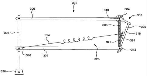
Embodiments of the invention permit equipoising of the load at far more
oblique
and far more acute angles than previously possible. In an illustrative
embodiment shown
in FIG. 20, this is accomplished by providing a force exerting device 300
having a load
arm 302 pivotable about a load pivot 312 and forming a first side of a force
exerting
structure 328. Although the term "triangle" is often used herein, the actual
shape of the
force exerting structure can vary somewhat from a true triangular form, for
example
because of connecting components that may protrude from the triangular form,
various
attachment points or additional structural sides. A resilient member 314
having a first
end 316 attached to the load arm and a second end 332 is attached to a
termination point
12
CA 02746546 2011-07-15
318, which is displaced from the load pivot 312 and forms a second side of the
force
exerting triangle. A third side of the force exerting triangle 320 extends
from the
termination point 318 to the load pivot 312. In this embodiment of the
invention the
termination point can be adjusted in more than one direction. In an exemplary
embodiment of the invention, a first adjustment mechanism moves the
termination point
318 to change the length of the third side 320 of the force exerting triangle
328. A
second adjustment mechanism moves the termination point in a direction other
than the
direction produced by the first adjustment. In an illustrative embodiment of
the
invention, the second adjustment direction is substantially perpendicular to
the first
adjustment direction. Examples of these two adjustment mechanisms are
designated by
Dx and Dy in FIGS. 5 and 7, although they need not be perpendicular as the "x"
and "y"
designations may imply.. Optimum choice of the two adjustments allows the
termination
point 318 location to cross a substantially plumb line 322 that passes through
the load
pivot 312 as the load arm 302 pivots about the load pivot 312. This alters the
equipoising contour throughout the pivotal excursion of the load arm as
compared to
prior art mechanisms in which the termination point did not cross the plumb
line. It is
noted that a single adjustment may be used to accomplish the same as two
separate
adjustment mechanisms. Additionally, a third adjustment mechanism can be
included to
move the termination point outside the plane of movement created by the other
adjustment mechanism(s).
A turnbuckle or other threaded adjustment mechanism, may be used to produce at
least one of the adjustments. Other adjustment mechanisms are within the
spirit and
scope of the invention. The adjustment amounts may be made in discrete
increments or
may span a continuous spectrum of values.
Another illustrative embodiment may provide additional equipoising ability by
having a force modification 304 device functionally connected to the third
triangle side
320 to produce dynamic movement of the termination point 318 in response to
motion of
the load arm 302 around the load pivot 312. The force modification device may
be for
example, a crankshaft or a cam. The force modification device causes the third
side of
the force exerting triangle 320 to move toward and away from plumb line 322 as
load
arm 302 moves. The amount termination point 318 moves, and where within load
arm
13
CA 02746546 2011-07-15
320's excursion it moves, is controlled by the shape and position of the
center point of the
cam. Movement of the termination point in this manner puts it in different
positions as
compared to the prior art and causes resilient member 314's length and
distribution of
forces created by it to differ compared to the prior art, where the position
of end 318 was
not dynamically modified. These changes created by the force modification
device
enable the inventive support arm to behave in a more desirable manner at the
extremes of
the arm's excursion as compared to prior art arms. Equipoising of the load at
far more
oblique and far more acute angles is now possible.
It is noted that parts described as being "connected" to one another, include
direct
connections and indirect connections, such as where a coupling-type part or
parts may be
used.
As load arm 302 is swung through its excursion, such as upward or downward,
resilient member 314 expands or contracts thereby changing the force it exerts
at a
particular rate. This rate can be modified by the force modification device at
particular
points along the excursion of load arm 302. The force modification device
preferably
decelerates this rate of change at the extremes of excursion, namely toward or
near
positive and negative 90 , thereby smoothing out the motion by reducing
lockup, lurching
etc. In a particular embodiment of the invention, the force modification
device causes
eccentric movement of the termination point, such as by use of an irregularly
shaped cam.
The force exerting device may include a pivotal parallelogram structure
wherein
load arm 302 is a side of the parallelogram. Two such parallelograms can be
pivotally
connected to form a bendable or pivotable force exerting device. Non-
parallelogram
forms of the force exerting device may also be linked together.
The force exerting device may also have an attachment mechanism to attach load
arm 302 to a movable carrier for operation as a portable device.
The fixed adjustment mechanisms may be motorized and May be computer
controlled. The computer control system may include a program to control one
or more
of the adjustments in response to sensed input. One or more of the adjustment
mechanisms may be manually controlled by a component displaced from the arm,
such as
a foot peddle.
The first and second adjustments may be computer controlled.
14
CA 02746546 2011-07-15
The invention also includes a method of exerting forces on objects. A force
exerting device such as described herein is provided. The termination point is
adjusted to
change the length of the third side of the force exerting triangle to change
the lifting
power of the force exerting triangle. The termination point is further
adjusted in a
direction that is substantially perpendicular to the first adjustment
direction so as the load
arm pivots about the load pivot the termination point location can cross a
substantially
plumb line passing through the load pivot to alter the equipoising contour
over at least
part of the pivotal excursion of the load arm. In a particular embodiment of
the
invention, the method further includes adjusting the termination point so that
the first and
second adjustments are proportional. In yet another embodiment of the
invention, the
method further includes dynamically moving the termination point in response
to motion
of the load arm around the load pivot.
In further illustrative embodiments of the invention, the force exerting
device has
a dynamic termination point adjustment, but not necessarily the initial set
point
adjustments because in some applications this may not be necessary. For
example, when
the force exerting device is used in a particular product having a constant
load, and to
which no additional loads will be attached, the initial set points can be
factory
established, without the need for adjustment capabilities. Of course, one or
more
additional set point adjustment mechanisms can still be desirable and are
within the scope
of the invention. Generally, the force modification device will dynamically
adjust the
resilient member termination point position with respect to a substantially
plumb line that
passes through the load pivot based on motion of the load arm thereby varying
the
resilient member's exerted force. The dynamic adjustment may be eccentric such
as
described above. Other features described with respect to the embodiments
having two
initial termination point adjustments can be used with the dynamic adjustment
feature,
whether or not the initial termination set point adjustments are used.
FIG. 4 diagrammatically shows two positions of the lifting triangle ABC
incorporated within a parallelogram support linkage. Resilient member 403
forms a side
of the force-exerting triangle, which is here shown as lifting triangle ABC.
Resilient
member 403 is here shown, therefore as a tension spring. In this illustration,
side 401 is
in both positions contiguous with fixed side 405 and the spring attachment
point 419 is
CA 02746546 2011-07-15
located on the line between point A and pivot 426. In order to exactly counter
a weight
throughout the potential excursion of parallelogram 402, 404, 405, 406 as
shown, the
tensioning assembly would require the spring rate specified by the formula K
P/Dy
(where K = spring rate, P = load and Dy = height of side 401. The tension
spring would
only fit within the available diagonal distance BC as shown if an
impractically high
spring rate and an impractically low value for side 401 were employed.
(example: If P =
40 lbs a spring rate of 160 lbs/inch would exactly counter P if the length of
side 401 was
.25"). If the length of side 401 was increased, the weight of P would
necessarily increase
proportionately to remain in equilibrium with the lifting force of triangle
ABC.
FIG. 5 diagrammatically illustrates an exemplary mechanism to adjust spring
termination height and offset from side 505, and further diagrams a novel way
to
equipoise load P using a tensioning assembly of a rate that is inappropriate
according to
the above formula K=P/Dy but is useful for other reasons. The tensioning
assembly may,
for example, be specified to fit within the diagonal space of a parallelogram
without the
high spring rate and low aspect ratio that would otherwise be called for. If
the
termination point 519 of spring 503 is displaced outside of the adjacent, side
505 of the
parallelogram formed by sides 502, 504, 505 and 506, the lifting force becomes
generally
less efficient as the parallelogram is moved both upward and downward from the
level
attitude shown, and which is known in the art to provide an approximation of
equipoise.
Embodiments of the present invention introduce a mechanism to adjustably vary
this
offset in a manner that remains proportional to the changing height of the
lifting triangle.
The path 518 of potential spring termination points is angularly displaced
from line 521,
an extension of side 505, by means of Dx lead screw 514 which is adjusted by
knob 516
to arcuately pivot side 501 (path 518) at pivot point A, and thus offset
spring termination
point 519 with respect to side 505, which is here shown to be vertical. In
addition, Dy
adjusting knob 515 turns lead screw 513 to raise and lower spring termination
point 519
along spring termination path 518 in order to increase or decrease the lifting
force of the
triangle ABC.
FIG. 6 diagrammatically illustrates an illustrative embodiment of the
invention
which introduces the use of a generally circular cam 622 and cam follower 623
to further
equalize the force of the lifting triangle so that it may more closely
equipoise the load at
16
CA 02746546 2011-07-15
all values of angle 0. To accomplish this, cam 622 is fixed to link side 606
with its
center 617 offset from the fixed point and cam follower 623 is fixed to block
611. Block
611 is fixed to bearing shaft 609 which is adjustably fixed to spring carrier
612 by lead
screw 613 in a manner to pivot with block 610 around point A so as to
dynamically alter
(proportionally with the height of spring termination 619). (The line between
619 and
point A defines side 601 of the lifting triangle, which is also the Dy
distance.) The
cyclical motion of the cam follower 623 in response to the excursion of the
parallelogram
(of sides 602, 604, 605, 606) from 0 20 up to 160 provides a series of Dx
offsets that, if
diagrammatic and formulaic descriptions of this aspect of embodiments of the
invention.) The larger the distance between the parallelogram pivot 626 and
the cam
center 617, and the smaller the general radius of the cam shape, the steeper
the plotted
parabola, and therefore the more radical the cam effect on Dx offset 624 as
the
great as from 20 to 70 , which have hitherto been virtually uncontrollable
with respect to
predictably equipoising load P. It is noted that although the arm is shown in
the figures
with the resilient member above the arm, the entire apparatus can be inverted.
FIG. 7 illustrates another embodiment of the present invention that adds to
the
proportional to the height of Dy). Dx adjusting knob 716 turns Dx lead screw
714 to
adjustably position cam follower 623 with reference to bearing shaft 609 and
thus set the
value of offset 624 of spring termination 619, which is also momentarily
incremented or
decremented by the action of cam 622 driven by the excursion of side 606 of
the
Embodiments of the invention control the behavior of the arm at high/low
extremes (such as 70 ) so that typical problems such as lurching over centers
and
locking up may be solved by simply shortening the crank length. This
simultaneously
reduces the offset and increases the radicality of the cam effect to reduce Dx
as the arm
17
=
CA 02746546 2011-07-15
FIG. 8a diagrams another illustrative embodiment of the present invention
which,
substitutes for the cam of FIGS. 6 and 7, a crank linkage 825 with its wrist
pin pivot 817
fixedly offset on an extension of link 806, at distance 20 from link pivot
826. Movement
of parallelogram link 806 around pivot 826 between high and low values of
angle 0
moves crank pivot 817 through arcuate path 828, and thus crank 825, acting
through
outboard crank pivot 823, moves block 811 to produce an effect similar to that
of the
circular cam and follower of FIGS. 6 and 7 and likewise dynamically alters the
Dx offset
of spring termination 819 with respect to 821 in response to the excursion of
the
parallelogram. As with the cam configuration, the motion created by the crank
linkage
can be eccentric. Note that this alteration is likewise arcuate around pivot
point A and is
proportional to the height of side 801 (Dy). In the preferred embodiment
illustrated, note
that spring termination path 818 does not pass through point A. Spring
termination path
818 crosses over line 821 at crossover point 827. This provides that as Dy
distance 1 is
reduced by means of lead screw 813, the nominal Dx values will become negative
before
Dy is zero, at roughly the point that the chosen spring rate would have
equipoised a
diminished load P according to the above-stated formula (K=P/Dy). The higher
the spring
rate, the more the offset varies toward the 'outside' of the plumb line that
is approximated
by the substantially vertical leg of the parallelogram linkage.
FIG. 8b shows a closer detail of the illustrative embodiment of FIG. 8,
illustrating
that captive nut 829 within top bearing block 811 fixes lead screw 813
longitudinally so
that it may adjust the position of carrier 812 and its enclosed bearing along
lead screw
813. Dx offset distance 824 is momentarily altered by the circular -excursion
of pivot 817
through path 828 around pivot 826 as the position of link 806 moves between
low and
high values of angle 0 and actively causes crank 825 to pivotally vary the
angle of
bearing shaft 809 about point A. The resulting momentary variation in offset
824 is also
proportional to the adjustably fixed height of side 1 (Dy).
FIG. 9 diagrammatically illustrates an embodiment of the present invention, in
which the crank of FIGS. 8a-b is replaced by a turnbuckle assembly of variable
length.
Shortening the turnbuckle 932, has a twofold effect: it reduces the Dx value
and at the
same time causes the cam effect of the crank linkage comprising the turnbuckle
932 to
become more radical at the high and low extremes of angular motion of the
parallelogram
18
CA 02746546 2011-07-15
in angle 0. In another embodiment of the invention, fixedly raising or
lowering the
turnbuckle link pivot 917 with respect to the centerline of link 906 produces
offset
distance 933 between pivot 917 and the center line of link 906 that
respectively causes
the 'cam' effect to be more or less radical as 0 decreases and increases. For
example,
lowering the pivot 917 produces a negative offset distance 933 that decreases
the 'cam'
effect as 0 decreases and vice versa. Length 931 of crank linkage 925 controls
offset bx
(w/respect to line 921). Increasing the length creates a more oblique lifting
triangle,
while shortening the length causes it to be less oblique. It is noted that
other threaded
adjustment mechanisms are within the spirit and scope of the invention.
FIG. 10a is a partial isometric view of the mechanism of the preferred
embodiment of FIG. 9, illustrating the spatial positions of the trunnion
screws 34 that
define the parallelogram pivot positions. Spring 3 with terminal 35 and
associated
hardware terminates at pivot 19 on carrier 12 which rides up and down linear
bearing
shaft 9 in response to adjustment of lead screw 13 by knob 15. Turnbuckle
assembly 32
is expanded or collapsed by knob 16 which draws pivots 17 and 23 together or
apart and
performs the function diagrammed in FIG. 9 to pivot bottom bearing block 10
and
arcuately adjust point 19 in response to the excursion of the parallelogram
link 6 (not
shown), and proportionate to the height of carrier 12. Note that the
turnbuckle assembly
32 provides for the pivots to be closer together than possible with
conventional
turnbuckles and the adjusting knob 16 can be displaced away from the line
between the
pivots 17 and 23, and thus out of the way of the end block (not shown) as
employed in
embodiments of the invention.
FIG. 10b is an alternative angle of an isometric view of the mechanism of FIG.
10a showing the use of a loop end spring 3 extending from axle 36 to spring
link 37
which in turn is pivotally linked to carrier 12 which contains linear bearing
9a. This view
more clearly shows top bearing block 11 which forms the upper attachment of
linear
bearing shaft 9, and also illustrates the approximate centerline 47 of pivot
17 for
turnbuckle assembly 32.
FIG. 11 is an exploded isometric assembly drawing of the Mechanism of a single
complete arm segment of the preferred embodiment of the present invention,
which
illustrates the components of the Dx/Dy adjusting and dynamically moving
assembly.
19
CA 02746546 2011-07-15
End block 58 is pivotally attached to links 52a and 56a. Link 56a provides
attachment to
pivot 54 which engages the turnbuckle assembly 60. Bottom bearing block 62
engages
bearing shaft 59. Carrier 64 encloses bearing 59a and is driven along shaft 59
by lead
screw 66, which is longitudinally fixed within top bearing block 68 by captive
nut 70 and
which is turned by knob 72. End block 57 completes a parallelogram.
FIG. 12 is a cutaway side view of a single arm segment of a preferred
embodiment of the invention showing the pivot locations for mounting the arm
segment
to a supporting body and payload via end blocks 80 and 82, respectively, if
the arm is
deployed in the attitude shown, and to end blocks 82 and 80, respectively, if
the arm is
deployed inverted (not shown) which is an equally valid configuration. Note
that a
second arm segment can optionally be included, via a hinge (not shown),
between one of
the end blocks and either the support body or camera (neither is shown) as
appropriate.
(see FIG. 15)
FIG. 13 is a solid side representation of the complete, two-segment support
arm of
a preferred embodiment of the present invention. Support body (not shown)
mounting
hardware 98 is pivotally attached to 'upper' arm segment 90, which is
pivotally attached
via hinge 92 to 'forearm' segment 94, which is adapted for connection to the
payload
(such as a camera) using post 96. Note that if the arm were inverted, post 94
and body
mounting hardware 98 could simply be interchanged and the arm would lift
appropriately.
FIG. 14a-c display three views of a chambered extrusion formed into
parallelogram support arm links to provide a light, torsionally rigid member.
FIG 14a is
a perspective view and shows a solid outer surface, however, openings can
exist on the
surface. FIG. 14c shows an end view of the extruded chambers, which are
roughly
triangular in section in this embodiment, and which run the length of the
parallelogram
link as shown in the isometric view of FIG. 14b.
FIGS. 15a-b show views of a chambered extrusion formed into the parallelogram
end blocks of an illustrative embodiment. FIG. 15b shows a top view of the end
block
having chambered voids 20, which provide lightweight and torsional stiffness.
The
isometric view in FIG. 15a illustrates the extrusion formed into one of the
end blocks of
the preferred embodiment, yet does not display any of voids 20.
CA 02746546 2011-07-15
FIG. 16 plots Dx values (at three values of Dy) against a range of angles 0 of
parallelogram motion, from 200 to 160 and graphs the parabolic nature of Dx
travel when
Dx is varied by the crank linkage of the support arm embodiment of FIGS. 8 and
9.
The desired force exerting device specifications will depend at least in part
on the
materials and components used and the load supported by the device. These
parameters
must be balanced with various specifications such as cam shapes, crank axle
offsets, crank
lengths, spring rates and load lengths for optimum equipoised motion.
FIG. 17 diagrams the results of a graphical solution based on the following
formulas:
1) DX = -.095(0)2 + .332(a) -.156
2) D = SQRTRDX)2 + (DY)2]
3) S = SQRTRtsina, + DX)2 + (tcoscc+DY)2]
4) Si = (e_D2 s2),2,
5) H = SQRT[12 ¨ (S1)2]
6) If E Ma = 0, P=((F)(H)-(W/2) f, sina)/tsina
Wherein
P: Payload
DX, DY: Define a location for spring attachment
S: is the extended spring length
H: is a line perpendicular to S
a: is the arm angle
F: is the spring force = lc (As) + Initial Force
M: moment about point a.
The parabolic function as described above produces regular lift. The crank
effectively applies a reverse parabolic function to linearize it. Therefore,
if a zero offset is
selected, the 'ride' will be hard and non-iso-elastic. (at 70' with no
offset one must lift
10 lbs or push down with 8). With appropriate offset and `geo' curve mere
ounces suffice
at both ends with a single high-rate spring that fits into the diagonal of the
lifting triangle.
21
CA 02746546 2013-05-10
If a nominally appropriate offset position is selected but no 'cam' effect is
used,
the ride will be softer, but as nominal Dx increases, at some point the arm
lifting force will
be excessive at the top and insufficient at the bottom of range and the arm
will be impelled
over centers at both the top and bottom. At this time the lifting curve will
favor a point just
above center so the arm will leap up to that 'spring-lever point and be
sluggish for the
next 30 degrees upward and then will accelerate toward lockup.
According to illustrative embodiments of the invention, the arm's lift can be
reduced to zero and indeed sent into the negative (pushing down) by motorizing
the Dy
lead screw, in order, for example, to facilitate the use of an ultrasound
transducer without
the need for the operator to supply the downward force. Dx and dynamic
adjustments can
also be motorized. The Dx lead screw (or turnbuckle) can also be motorized.
Both Dy and
Dx can be dynamically controlled by a manual means (such as a foot pedal) or
by
computer, in response to outside stimuli, including the 'feel' to the
accompanying hand, or
a screen reference, such as the image on an ultrasound display screen. Each of
Dy and Dx
may be controlled in discrete increments or in a continuous manner.
While the invention has been described by illustrative embodiments, additional
advantages and modifications will occur to those skilled in the art.
Therefore, the
invention in its broader aspects is not limited to specific details shown and
described
herein.
22