Note: Descriptions are shown in the official language in which they were submitted.
BONE PLATE SCREW HOLES CONVERTIBLE TO HOOKS
Inventor: Abhishek MODI
Field of the Invention
[0001] The present invention relates to devices for treating fractures and, in
particular, to
a device including a spiked tip to be used in combination with a bone plate to
facilitate
reduction of a fracture.
Background
[0002] Rigid plates are often utilized to stabilize damaged or weakened
portions of bone,
for example, at fracture sites. These bone plates generally include openings
through which
bone fixation elements are inserted into the bone to anchor the plates to
target portions of
bone.
[0003] In some situations, however, small bone fragments are difficult to
maneuver
making compression across the damaged or weakened portion of the bone
difficult to
maintain while inserting bone fixation elements therethrough.
Summary of the Invention
[0004] The present invention is directed to a system for treating a bone,
comprising a
bone plate extending longitudinally from a first end to a second end and
including a
plurality of openings extending therethrough and a first hook member including
a head
sized and shaped to be lockingly received within a first one of the openings,
the first hook
member further including a spiked portion extending distally from the head to
a sharp bone
engaging distal end which,
1
CA 2786743 2017-08-10
CA 02786743 2012-07-10
WO 2011/106403
PCT/US2011/025898
when the head is lockingly received within the first opening, projects
distally from the bone plate
toward a first target portion of bone to be engaged thereby to temporarily
maintain the first target
of bone in a desired spatial relation to the bone plate.
[0005] The present invention is further directed to a method, comprising
lockingly coupling a
first hook member within a first hole through a bone plate so that a spiked
distal end of the first
hook member projects distally from a bone facing surface of the bone plate and
engaging the
spiked distal end of the first hook member with a first target portion of bone
to temporarily
maintain the first target portion of bone in a desired spatial relation to the
bone plate in
combination with inserting a first bone fixation element into a second target
portion of bone via a
second hole through the bone plate to permanently secure the second target
portion of bone to the
bone plate and removing the first hook member from the first hole after the
first bone fixation
element has secured the second target portion of bone to the bone plate.
Brief Description of the Drawings
[0006] Fig. 1 shows a perspective view of a system according to an exemplary
embodiment of
the present invention;
Fig. 2 shows a side view of the system of Fig. 1;
Fig. 3 shows a side view of a spike of the system of Fig. 1; and
Fig. 4 shows a top view of the spike of Fig. 3.
Detailed Description
[0007] The present invention may be further understood with reference to the
following
description and the appended drawings, wherein like elements are referred to
with the same
reference numerals. The present invention relates to devices for treating
fractures. In particular,
exemplary embodiments of the present invention describe a device including a
spiked tip to be
2
CA 02786743 2012-07-10
WO 2011/106403
PCT/US2011/025898
used in combination with a bone plate to facilitate reduction of a fracture.
It will be understood
by those of skill in the art that the terms proximal and distal, as used
herein, are used to refer to a
direction toward (proximal) and away from (distal) a user (e.g., surgeon) of
the device.
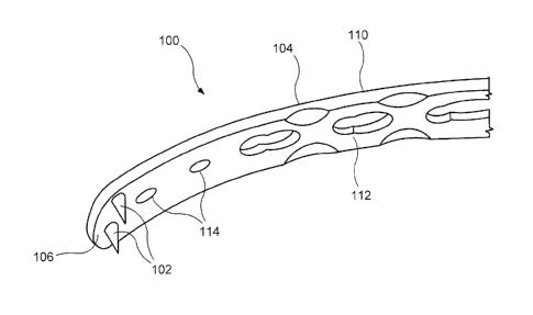
[0008] As shown in Figs. 1 and 2, a system 100 according to a first exemplary
embodiment of
the present invention comprises a hook member 102 couplable to a bone plate
104 to provide the
bone plate 104 with hooks to facilitate reduction of a fracture. In some
situations (e.g., involving
small bone fragments) the fragments may be difficult to maneuver, thereby
resulting in
insufficient reduction of the fracture and/or difficulty maintaining the
reduction. The hook
member 102 facilitates a preliminary fixation, allowing compression across the
fracture using the
bone plate 104 as a tension band. The preliminary fixation permits bone
fixation elements to be
easily inserted into the bone through the bone plate 104 to anchor the bone
plate 104 to the bone
while maintaining compression of the fracture. In an exemplary embodiment, the
system 100
includes at least two hook members 102 at opposite ends of the bone plate 104.
It will be
understood by those of skill in the art, however, that the system 100 may
include any number of
hook members 102 and any number of locations at which they may be coupled to
the bone plate
104 so long as the hook members 102 are positioned to engage target portions
of the bone to
facilitate a preliminary fixation of the bone.
[0009] The bone plate 104 extends longitudinally from a first end 106 to a
second end 108 and
includes a first surface 110 which, when in an operative position, faces away
from the bone, and
a second surface 112 which, when in an operative position, faces toward the
bone. The bone
plate 104 further includes a plurality of openings 114 extending therethrough,
from the first
surface 110 to the second surface 112. The openings 114 may be configured and
adapted to
receive the hook member 102 as well as bone fixation elements such as screws,
nails and pins.
The openings 114 may include an engagement mechanism such as, for example, a
threading (not
shown) along an inner surface thereof for engaging a portion of the hook
member 102. The bone
plate 104 may be an olecranon plate or a distal humerus plate. It will be
understood by those of
skill in the art, however, that the bone plate 104 may be any kind of bone
plate that may be used
3
CA 02786743 2012-07-10
WO 2011/106403
PCT/US2011/025898
to fix fractures. For this purpose, it is preferred to use standard locking
holes configured to
lockingly engage the heads of standard bone fixation elements such as screw
and pins.
[0010] The hook member 102 includes a head portion 116 and a spiked portion
118 extending
distally therefrom. The head portion 116 is sized and shaped to be received
within a hook
member opening 114 extending through the bone plate 104. The head portion 116
may include
an engaging element such as, for example, threading (not shown) extending
around an outer
surface thereof to engage corresponding threading in the opening 114. As would
be understood
by those skilled in the art, if the openings 114 are standard locking holes,
the head portion 116
will preferably be foirned substantially similarly to the head portion of a
bone fixation element to
be coupled therein. The head portion 116 may further include a driving element
120 at a
proximal end 122 thereof sized and shaped to engage a portion of a driving
tool used to rotate the
hook member 102 into threaded engagement with the opening 114 as would be
understood by
those skilled in the art to releasably fix the hook member 102 to the bone
plate 104. The driving
element 120 may be a recess at the proximal end 122 sized and shaped to
receive a
correspondingly shaped portion of the driving tool. For example, the driving
element 120 may
be a hexagonally shaped recess for engaging a hex-shaped portion of the
driving tool.
Alternatively, the driving element 120 may be a protrusion extending from the
proximal end 122,
the protrusion being sized and shaped to engage the driving tool.
100111 The spiked portion 118 may be attached to a distal end 124 of the head
portion 116 via a
neck portion 132 with the spiked portion II 8 extending distally therefrom. A
diameter of the
neck portion 132 in this embodiment is smaller than a diameter of the head
portion 116 with the
spiked portion 118 tapering from a proximal end 126 thereof (at the distal end
of the neck portion
132) to a distal end 128 which ends in a sharp tip 130. The angle of this
taper preferably ranges
between approximately 15 and 45 . However, the taper angle will vary
depending on a number
of factors such as, for example, a desired length of the hook member 102, a
desired strength of
the hook member 102 and a hardness of the bone being treated. A length of the
head portion 116
and the neck portion 132 is selected so that, when the hook member 102 is
fully engaged with the
4
CA 02786743 2012-07-10
WO 2011/106403
PCT/US2011/025898
opening 114, the spiked portion 118 extends distally from the second surface
112 of the bone
plate 104 toward the portion of bone it is to engage. The sharp tip 130 is
pressed into this target
portion of bone to hold the bone plate 104 and this target portion of bone in
a desired spatial
relationship to one another, at least until the plate 104 is permanently
coupled to the various
portions of the bone. The sharp tip 130 may be impacted into the bone and/or
engaged with a
pre-drilled hole in the bone.
[0012] In a preferred embodiment, the system 100 includes at least two hook
members 102,
with each hook member 102 inserted into a corresponding opening 114. For
example, a first one
of the hook members 102 may be inserted into an opening 114 at a first end 106
of the plate 104
while a second one of the hook members 102 is inserted into an opening 114 at
a second end 108
of the plate 104. The bone plate 104 according to this embodiment includes a
plurality of
openings 114 positioned to enable a user to mount a desired number of the hook
members 102 at
positions on the plate 104 corresponding to a plurality of target portions of
bone to be
temporarily held in place. Openings 114 are included at each of the first and
second ends 106,
108, for example, to allow the bone plate 104 to be coupled across a fracture
site via hook
members 102 to preliminarily fix a portion of the bone prior to the insertion
of peimanent bone
fixation elements (e.g., bone screws, pins, etc.). It will be understood by
those of skill in the art,
however, that the openings 114 may be positioned at any desired locations on
the plate 104
suitable to facilitate engagement of hook members 102 with target portions of
the bone.
[0013] A method according to the present invention may include preassembly of
the hook
member 102 with the bone plate 104 prior to a procedure. For example, any
number of hook
members 102 may be inserted into a corresponding openings 114 and coupled to
the plate 104 as
described above via, for example, rotation about central axes of the openings
114 to engage
threads of the head portions 116 with threads of the openings 114. The plate
104 may then be
placed on the bone over target portions or fragments thereof in a known
manner. The user then
engages the target portions of bone with the corresponding hook members 102 to
temporarily
hold the bone fragments in place. For example, the hook members 102 may be
impacted into the
CA 02786743 2012-07-10
WO 2011/106403
PCT/US2011/025898
target portions of the bone using a bone tamp, a mallet and/or other impaction
device.
Alternatively, the bone may be pre-drilled with small holes corresponding to a
position of each of
the hook members 102 such that the sharp tips 130 engage the pre-drilled holes
when the plate
104 is placed over and pressed into the bone. The user then places any desired
number of
conventional bone fixation elements (e.g., bone screws or pins) through other
openings in the
plate to permanently anchor the bone plate 104 to the bone. As would be
understood by those
skilled in the art, the bone plate 104 may include any number and variety of
bone fixation
receiving holes such as combination holes, compression holes, variable angle
locking holes, etc.
100141 Once the bone plate 104 has been appropriately anchored to the bone,
the hook
members 102 may be removed from the bone plate 104 via, for example, rotating
the hook
members 102 about the central axis of the opening in a direction opposite that
used to couple the
hook members 102 therein. Upon removal of each of the hook members 102, a bone
fixation
element may be inserted into the opening 114 vacated by the hook member 102 to
provide
additional fixation of the bone plate 104. Thus, it will be understood by
those of skill in the art
that an advantage of the system 100 is the removable coupling of the hook
members 102 to the
bone plate 104.
100151 It will be apparent to those skilled in the art that various
modifications and variations
can be made in the structure and the methodology of the present invention,
without departing
from the spirit or scope of the invention. Thus, it is intended that the
present invention cover the
modifications and variations of the invention provided that they come within
the scope of the
appended claims and their equivalents.
6