Note: Claims are shown in the official language in which they were submitted.
40
Claims
1. A cartridge assembly comprising:
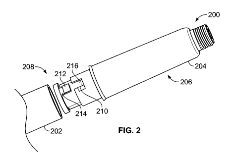
a cartridge holder (104, 204, 302, 402, 802, 902, 922),
a cartridge (119, 206, 304, 404),
the cartridge holder (104, 204, 302, 402, 802, 902, 922) being provided with a
first fastening feature (210, 310, 312, 408, 412, 504, 604a, 604b, 604c, 702,
703, 806,
908, 928);
the cartridge (119, 206, 304, 404) being provided with a second fastening
feature
(212, 314, 316, 410, 414, 416, 502, 602a, 602b, 602c, 700, 701, 804, 906,
926),
the first fastening feature (210, 310, 312, 408, 412, 504, 604a, 604b, 604c,
702,
703, 806, 908, 928) and the second fastening feature (212, 314, 316, 410, 414,
416,
502, 602a, 602b, 602c, 700, 701, 804, 906, 926) being provided as a fastener
of the
cartridge assembly (200, 300, 400, 900) to a drug delivery device (100, 202,
500, 600a,
600b, 600c, 704); and
a connector (208, 306, 406, 800, 904, 924) that is attached to the cartridge
(119,
206, 304, 404), wherein the second fastening feature (212, 314, 316, 410, 414,
416,
502, 602a, 602b, 602c, 700, 701, 804, 906, 926) is provided on the connector.
2. The cartridge assembly of claim 1, wherein the first fastening feature
(210, 310,
312, 408, 412, 504, 604a, 604b, 604c, 702, 703, 806, 908, 928) is a protrusion
from the
cartridge holder (104, 204, 302, 402, 802, 902, 922) and the second fastening
feature
(212, 314, 316, 410, 414, 416, 502, 602a, 602b, 602c, 700, 701, 804, 906, 926)
is a
protrusion from the connector (208, 306, 406, 800, 904, 924).
3. The cartridge assembly of claim 1 or 2, wherein the connector (208, 306,
406,
800, 904, 924) allows the cartridge holder (104, 204, 302, 402, 802, 902, 922)
to be
connected to a drug delivery device (100, 202, 500, 600a, 600b, 600c, 704)
when the
connector (208, 306, 406, 800, 904, 924) is attached to the cartridge (119,
206, 304,
404).
41
4. The cartridge assembly of one of claims 1 to 3, wherein the connector (208,
306,
406, 800, 904, 924) comprises a non-rotation feature (330) that prevents
relative
rotation between the cartridge holder (104, 204, 302, 402, 802, 902, 922) and
the
connector (208, 306, 406, 800, 904, 924).
5. The cartridge assembly of one of claims 1 to 4, wherein the connector (208,
306,
406, 800, 904, 924) is fitted around a sidewall of the cartridge (119, 206,
304, 404).
6. The cartridge assembly of one of claims 1 to 5, wherein the connector (208,
306,
406, 800, 904, 924) is coded to the cartridge holder (104, 204, 302, 402, 802,
902, 922)
or wherein the first fastening feature (210, 310, 312, 408, 412, 504, 604a,
604b, 604c,
702, 703, 806, 908, 928) and the second fastening feature (212, 314, 316, 410,
414,
416, 502, 602a, 602b, 602c, 700, 701, 804, 906, 926) are coded to a drug
delivery
device (100, 202, 500, 600a, 600b, 600c, 704).
7. The cartridge assembly of one of claims 1 to 6, wherein
the connector (208, 306, 406, 800, 904, 924) has a first sidewall (808) that
extends a partial extent of the circumference of the connector (208, 306, 406,
800, 904,
924),
the cartridge holder (104, 204, 302, 402, 802, 902, 922) has a second sidewall
(810) that extends a partial extent of the circumference of the cartridge
holder (104,
204, 302, 402, 802, 902, 922), and
the first sidewall (808) and the second sidewall (810) combine to form a
complete
circumference when the connector (208, 306, 406, 800, 904, 924) and the
cartridge
holder (104, 204, 302, 402, 802, 902, 922) are attached.
8. The cartridge assembly of claim 7, wherein the connector (208, 306, 406,
800,
904, 924) is coded to the cartridge holder (104, 204, 302, 402, 802, 902, 922)
by an
angle of the first sidewall (808).
42
9. The cartridge assembly of claim 7 or 8, wherein the first fastening feature
(210,
310, 312, 408, 412, 504, 604a, 604b, 604c, 702, 703, 806, 908, 928) is located
on the
second sidewall (810), and wherein the second fastening feature (212, 314,
316, 410,
414, 416, 502, 602a, 602b, 602c, 700, 701, 804, 906, 926) is located on the
first
sidewall (808).
10. The cartridge assembly of one of claims 2 to 9, further comprising:
protrusions (214, 324, 326, 328, 410) and indentations (216, 318, 320, 322,
418) on the
connector (208, 306, 406, 800, 904, 924) and on the cartridge holder (104,
204, 302,
402, 802, 902, 922), the protrusions (214, 324, 326, 328, 410) and
indentations (216,
318, 320, 322, 418) being provided as coding features.
11. The cartridge assembly of one of claims 1 to 10, wherein the first
fastening
feature (210, 310, 312, 408, 412, 504, 604a, 604b, 604c, 702, 703, 806, 908,
928) and
the second fastening feature (212, 314, 316, 410, 414, 416, 502, 602a, 602b,
602c,
700, 701, 804, 906, 926) are adapted to a groove (230, 506, 706, 708) of a
drug
delivery device (100, 202, 500, 600a, 600b, 600c, 704), the groove (230, 506,
706, 708)
having an ejection channel (238, 608a, 608b, 608c, 712, 713), the first
fastening feature
(210, 310, 312, 408, 412, 504, 604a, 604b, 604c, 702, 703, 806, 908, 928)
being able to
enter the ejection channel (238, 608a, 608b, 608c, 712, 713) and the second
fastening
feature (212, 314, 316, 410, 414, 416, 502, 602a, 602b, 602c, 700, 701, 804,
906, 926)
being prevented from entering the ejection channel (238, 608a, 608b, 608c,
712, 713).
12. The cartridge assembly of one of claims 1 to 11, wherein the first
fastening
feature (210, 310, 312, 408, 412, 504, 604a, 604b, 604c, 702, 703, 806, 908,
928) and
the second fastening feature (212, 314, 316, 410, 414, 416, 502, 602a, 602b,
602c,
700, 701, 804, 906, 926) together form a pin-type fastening means.
13. The cartridge assembly of one of claims 1 to 11, wherein the first
fastening
feature (210, 310, 312, 408, 412, 504, 604a, 604b, 604c, 702, 703, 806, 908,
928) and
43
the second fastening feature (212, 314, 316, 410, 414, 416, 502, 602a, 602b,
602c,
700, 701, 804, 906, 926) together form a groove.
14. The cartridge assembly of one of claims 1 to 13, wherein the first
fastening
feature (210, 310, 312, 408, 412, 504, 604a, 604b, 604c, 702, 703, 806, 908,
928) and
the second fastening feature (212, 314, 316, 410, 414, 416, 502, 602a, 602b,
602c,
700, 701, 804, 906, 926) comprise at least two sets of fastening features.
15. A drug delivery device comprising
a groove (230, 506, 706, 708) with an ejection channel (238, 608a, 608b, 608c,
712, 713), and
a cartridge assembly (200, 300, 400, 900) with
a cartridge holder (104, 204, 302, 402, 802, 902, 922),
a connector (208, 306, 406, 800, 904, 924), which is provided to be attached
to a
cartridge (119, 206, 304, 404),
a first fastening feature (210, 310, 312, 408, 412, 504, 604a, 604b, 604c,
702,
703, 806, 908, 928) of the cartridge holder (104, 204, 302, 402, 802, 902,
922), and
a second fastening feature (212, 314, 316, 410, 414, 416, 502, 602a, 602b,
602c,
700, 701, 804, 906, 926) of the connector (208, 306, 406, 800, 904, 924),
the first fastening feature (210, 310, 312, 408, 412, 504, 604a, 604b, 604c,
702,
703, 806, 908, 928) and the second fastening feature (212, 314, 316, 410, 414,
416,
502, 602a, 602b, 602c, 700, 701, 804, 906, 926) moving in the groove (230,
506, 706,
708) when the cartridge holder (104, 204, 302, 402, 802, 902, 922), provided
with a
cartridge (119, 206, 304, 404) and the connector (208, 306, 406, 800, 904,
924), is
being attached, and
the first fastening feature (210, 310, 312, 408, 412, 504, 604a, 604b, 604c,
702,
703, 806, 908, 928) entering the ejection channel (238, 608a, 608b, 608c, 712,
713)
during an attempt to attach the cartridge holder (104, 204, 302, 402, 802,
902, 922)
when the cartridge holder (104, 204, 302, 402, 802, 902, 922) is not provided
with a
cartridge (119, 206, 304, 404) and the connector (208, 306, 406, 800, 904,
924).
44
16. The drug delivery device of claim 15, further comprising:
a spring mechanism, which rotates the cartridge assembly (200, 300, 400, 900)
toward the ejection channel (238, 608a, 608b, 608c, 712, 713) in order to
ensure that a
cartridge (119, 206, 304, 404) is rejected if the connector (208, 306, 406,
800, 904, 924)
is not fitted.
17. The drug delivery device of claim 16, further comprising:
a second spring mechanism, which forces the cartridge assembly (200, 300, 400,
900) along the ejection channel (238, 608a, 608b, 608c, 712, 713) to ensure
that the
cartridge (119, 206, 304, 404) is rejected if the connector (208, 306, 406,
800, 904, 924)
is not fitted.