Note: Descriptions are shown in the official language in which they were submitted.
Parallel Cycle Heat Engines
[0001]
Background
[0002] Heat is often created as a byproduct of industrial processes where
flowing streams of
liquids, solids, or gasses that contain heat must be exhausted into the
environment or otherwise
removed from the process in an effort to maintain the operating temperatures
of the industrial
process equipment. Sometimes the industrial process can use heat exchanging
devices to
capture the heat and recycle it back into the process via other process
streams. Other times it
is not feasible to capture and recycle this heat because it is either too low
in temperature or
there is no readily available means to use as heat directly. This type of heat
is generally referred
to as "waste" heat, and is typically discharged directly into the environment
through, for
example, a stack, or indirectly through a cooling medium, such as water. In
other settings, such
heat is readily available from renewable sources of thermal energy, such as
heat from the sun
(which may be concentrated or otherwise manipulated) or geothermal sources.
These and other
thermal energy sources are intended to fall within the definition of "waste
heat," as that term is
used herein.
[0003] Waste heat can be utilized by turbine generator systems which employ
thermodynamic
methods, such as the Rankine cycle, to convert heat into work. Typically, this
method is steam-
based, wherein the waste heat is used to raise steam in a boiler to drive a
turbine. However, at
least one of the key short-comings of a steam-based Rankine cycle is its high
temperature
requirement, which is not always practical since it generally requires a
relatively high
temperature (600 F or higher, for example) waste heat stream or a very large
overall heat
content. Also, the complexity of boiling water at multiple
pressures/temperatures to capture heat
at multiple temperature levels as the heat source stream is cooled is costly
in both equipment
cost and operating labor. Furthermore, the steam-based Rankine cycle is not a
realistic option
for streams of small flow rate and/or low temperature.
[0004] The organic Rankine cycle (ORC) addresses the short-comings of the
steam-based
Rankine cycles by replacing water with a lower boiling-point fluid, such as a
light hydrocarbon
like propane or butane, or a HCFC (e.g., R245fa) fluid. However, the boiling
heat transfer
restrictions remain, and new issues such as thermal instability, toxicity or
flammability of the
fluid are added.
1
CA 2820606 2018-05-23
CA 02820606 2013-05-23
WO 2012/074905 PCT/US2011/062198
[0005] To address these short-comings, supercritical CO2 power cycles have
been used. The
supercritical state of the CO2 provides improved thermal coupling with
multiple heat sources. For
example, by using a supercritical fluid, the temperature glide of a process
heat exchanger can be
more readily matched. However, single cycle supercritical CO2 power cycles
operate over a limited
pressure ratio, thereby limiting the amount of temperature reduction, i.e.,
energy extraction, through
the power conversion device (typically a turbine or positive displacement
expander). The pressure
ratio is limited primarily due to the high vapor pressure of the fluid at
typically available
condensation temperatures (e.g., ambient). As a result, the maximum output
power that can be
achieved from a single expansion stage is limited, and the expanded fluid
retains a significant
amount of potentially usable energy. While a portion of this residual energy
can be recovered
within the cycle by using a heat exchanger as a recuperator, and thus pre-
heating the fluid between
the pump and waste heat exchanger, this approach limits the amount of heat
that can be extracted
from the waste heat source in a single cycle.
[0006] Accordingly, there exists a need in the art for a system that can
efficiently and effectively
produce power from not only waste heat, but also from a wide range of thermal
sources.
Summary
[0007] Embodiments of the disclosure may provide a system for converting
thermal energy to work.
The system may include a pump configured to circulate a working fluid
throughout a working fluid
circuit, the working fluid being separated into a first mass flow and a second
mass flow downstream
from the pump, and a first heat exchanger fluidly coupled to the pump and in
thermal
communication with a heat source, the first heat exchanger being configured to
receive the first
mass flow and transfer heat from the heat source to the first mass flow. The
system may also
include a first turbine fluidly coupled to the first heat exchanger and
configured to expand the first
mass flow, and a first recuperator fluidly coupled to the first turbine and
configured to transfer
residual thermal energy from the first mass flow discharged from the first
turbine to the first mass
flow directed to the first heat exchanger. The system may further include a
second heat exchanger
fluidly coupled to the pump and in thermal communication with the heat source,
the second heat
exchanger being configured to receive the second mass flow and transfer heat
from the heat
source to the second mass flow, and a second turbine fluidly coupled to the
second heat exchanger
and configured to expand the second mass flow.
[0008] Embodiments of the disclosure may further provide another system for
converting thermal
energy to work. The additional system may include a pump configured to
circulate a working fluid
throughout a working fluid circuit, the working fluid being separated into a
first mass flow and a
second mass flow downstream from the pump, a first heat exchanger fluidly
coupled to the pump
and in thermal communication with a heat source, the first heat exchanger
being configured to
2
CA 02820606 2013-05-23
WO 2012/074905 PCT/US2011/062198
receive the first mass flow and transfer heat from the heat source to the
first mass flow, and a first
turbine fluidly coupled to the first heat exchanger and configured to expand
the first mass flow. The
system may also include a first recuperator fluidly coupled to the first
turbine and configured to
transfer residual thermal energy from the first mass flow discharged from the
first turbine to the first
mass flow directed to the first heat exchanger, a second heat exchanger
fluidly coupled to the pump
and in thermal communication with the heat source, the second heat exchanger
being configured to
receive the second mass flow and transfer heat from the heat source to the
second mass flow, and
a second turbine fluidly coupled to the second heat exchanger and configured
to expand the
second mass flow, the second mass flow being discharged from the second
turbine and re-
combined with the first mass flow to generate a combined mass flow. The system
may further
include a second recuperator fluidly coupled to the second turbine and
configured to transfer
residual thermal energy from the combined mass flow to the second mass flow
directed to the
second heat exchanger, and a third heat exchanger in thermal communication
with the heat source
and arranged between the pump and the first heat exchanger, the third heat
exchanger being
configured to receive and transfer heat to the first mass flow prior to
passing through the first heat
exchanger
[0009] Embodiments of the disclosure may further provide a method for
converting thermal energy
to work. The method may include circulating a working fluid with a pump
throughout a working fluid
circuit, separating the working fluid in the working fluid circuit into a
first mass flow and a second
mass flow, and transferring thermal energy in a first heat exchanger from a
heat source to the first
mass flow, the first heat exchanger being in thermal communication with the
heat source. The
method may also include expanding the first mass flow in a first turbine
fluidly coupled to the first
heat exchanger, transferring residual thermal energy in a first recuperator
from the first mass flow
discharged from the first turbine to the first mass flow directed to the first
heat exchanger, the first
recuperator being fluidly coupled to the first turbine, and transferring
thermal energy in a second
heat exchanger from the heat source to the second mass flow, the second heat
exchanger being in
thermal communication with the heat source. The method may further include
expanding the
second mass flow in a second turbine fluidly coupled to the second heat
exchanger.
Brief Description of the Drawings
[0010] The present disclosure is best understood from the following detailed
description when read
with the accompanying Figures. It is emphasized that, in accordance with the
standard practice in
the industry, various features are not drawn to scale. In fact, the dimensions
of the various features
may be arbitrarily increased or reduced for clarity of discussion.
[0011] Figure 1 schematically illustrates an exemplary embodiment of a
parallel heat engine cycle,
according to one or more embodiments disclosed.
3
CA 02820606 2013-05-23
WO 2012/074905 PCT/US2011/062198
[0012] Figure 2 schematically illustrates another exemplary embodiment of a
parallel heat engine
cycle, according to one or more embodiments disclosed.
[0013] Figure 3 schematically illustrates another exemplary embodiment of a
parallel heat engine
cycle, according to one or more embodiments disclosed.
[0014] Figure 4 schematically illustrates another exemplary embodiment of a
parallel heat engine
cycle, according to one or more embodiments disclosed.
[0015] Figure 5 schematically illustrates another exemplary embodiment of a
parallel heat engine
cycle, according to one or more embodiments disclosed.
[0016] Figure 6 schematically illustrates another exemplary embodiment of a
parallel heat engine
cycle, according to one or more embodiments disclosed.
[0017] Figure 7 schematically illustrates an exemplary embodiment of a mass
management system
(MMS) which can be implemented with a parallel heat engine cycle, according to
one or more
embodiments disclosed.
[0018] Figure 8 schematically illustrates another exemplary embodiment of a
MMS which can be
implemented with a parallel heat engine cycle, according to one or more
embodiments disclosed.
[0019] Figures 9 and 10 schematically illustrate different system arrangements
for inlet chilling of a
separate stream of fluid (e.g., air) by utilization of the working fluid which
can be used in parallel
heat engine cycles disclosed herein.
Detailed Description
[0020] It is to be understood that the following disclosure describes several
exemplary
embodiments for implementing different features, structures, or functions of
the invention.
Exemplary embodiments of components, arrangements, and configurations are
described below to
simplify the present disclosure; however, these exemplary embodiments are
provided merely as
examples and are not intended to limit the scope of the invention.
Additionally, the present
disclosure may repeat reference numerals and/or letters in the various
exemplary embodiments
and across the Figures provided herein. This repetition is for the purpose of
simplicity and clarity
and does not in itself dictate a relationship between the various exemplary
embodiments and/or
configurations discussed in the various Figures. Moreover, the formation of a
first feature over or
on a second feature in the description that follows may include embodiments in
which the first and
second features are formed in direct contact, and may also include embodiments
in which
additional features may be formed interposing the first and second features,
such that the first and
second features may not be in direct contact. Finally, the exemplary
embodiments presented below
may be combined in any combination of ways, i.e., any element from one
exemplary embodiment
4
CA 02820606 2013-05-23
WO 2012/074905 PCT/US2011/062198
may be used in any other exemplary embodiment, without departing from the
scope of the
disclosure.
[0021] Additionally, certain terms are used throughout the following
description and claims to refer
to particular components. As one skilled in the art will appreciate, various
entities may refer to the
same component by different names, and as such, the naming convention for the
elements
described herein is not intended to limit the scope of the invention, unless
otherwise specifically
defined herein. Further, the naming convention used herein is not intended to
distinguish between
components that differ in name but not function. Additionally, in the
following discussion and in the
claims, the terms "including" and "comprising" are used in an open-ended
fashion, and thus should
be interpreted to mean "including, but not limited to." All numerical values
in this disclosure may be
exact or approximate values unless otherwise specifically stated.
Accordingly, various
embodiments of the disclosure may deviate from the numbers, values, and ranges
disclosed herein
without departing from the intended scope. Furthermore, as it is used in the
claims or specification,
the term "or" is intended to encompass both exclusive and inclusive cases,
i.e., "A or B" is intended
to be synonymous with "at least one of A and B," unless otherwise expressly
specified herein.
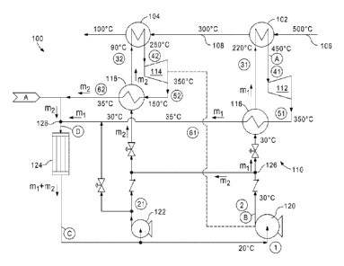
[0022] Figure 1 illustrates an exemplary thermodynamic cycle 100, according to
one or more
embodiments of the disclosure that may be used to convert thermal energy to
work by thermal
expansion of a working fluid. The cycle 100 is characterized as a Rankine
cycle and may be
implemented in a heat engine device that includes multiple heat exchangers in
fluid communication
with a waste heat source, multiple turbines for power generation and/or pump
driving power, and
multiple recuperators located downstream of the turbine(s).
[0023] Specifically, the thermodynamic cycle 100 may include a working fluid
circuit 110 in thermal
communication with a heat source 106 via a first heat exchanger 102, and a
second heat
exchanger 104 arranged in series. It will be appreciated that any number of
heat exchangers may
be utilized in conjunction with one or more heat sources. In one exemplary
embodiment, the first
and second heat exchangers 102, 104 may be waste heat exchangers. In other
exemplary
embodiments, the first and second heat exchangers 102, 104 may include first
and second stages,
respectively, of a single or combined waste heat exchanger.
[0024] The heat source 106 may derive thermal energy from a variety of high
temperature sources.
For example, the heat source 106 may be a waste heat stream such as, but not
limited to, gas
turbine exhaust, process stream exhaust, or other combustion product exhaust
streams, such as
furnace or boiler exhaust streams. Accordingly, the thermodynamic cycle 100
may be configured to
transform waste heat into electricity for applications ranging from bottom
cycling in gas turbines,
stationary diesel engine gensets, industrial waste heat recovery (e.g., in
refineries and compression
stations), and hybrid alternatives to the internal combustion engine. In
other exemplary
CA 02820606 2013-05-23
WO 2012/074905 PCT/US2011/062198
embodiments, the heat source 106 may derive thermal energy from renewable
sources of thermal
energy such as, but not limited to, solar thermal and geothermal sources.
[0025] While the heat source 106 may be a fluid stream of the high temperature
source itself, in
other exemplary embodiments the heat source 106 may be a thermal fluid in
contact with the high
temperature source. The thermal fluid may deliver the thermal energy to the
waste heat
exchangers 102, 104 to transfer the energy to the working fluid in the circuit
100.
[0026] As illustrated, the first heat exchanger 102 may serve as a high
temperature, or relatively
higher temperature, heat exchanger adapted to receive an initial or primary
flow of the heat source
106. In various exemplary embodiments of the disclosure, the initial
temperature of the heat source
106 entering the cycle 100 may range from about 400 F to greater than about
1,200 F (about
204 C to greater than about 650 C). In the illustrated exemplary embodiment,
the initial flow of the
heat source 106 may have a temperature of about 500 C or higher. The second
heat exchanger
104 may then receive the heat source 106 via a serial connection 108
downstream from the first
heat exchanger 102. In one exemplary embodiment, the temperature of the heat
source 106
provided to the second heat exchanger 104 may be about 250-300 C. It should be
noted that
representative operative temperatures, pressures, and flow rates as indicated
in the Figures are by
way of example and are not in any way to be considered as limiting the scope
of the disclosure.
[0027] As can be appreciated, a greater amount of thermal energy is
transferred from the heat
source 106 via the serial arrangement of the first and second heat exchangers
102, 104, whereby
the first heat exchanger 102 transfers heat at a relatively higher temperature
spectrum in the waste
heat stream 106 than the second heat exchanger 104. Consequently, greater
power generation
results from the associated turbines or expansion devices, as will be
described in more detail
below.
[0028] The working fluid circulated in the working fluid circuit 110, and the
other exemplary circuits
disclosed herein below, may be carbon dioxide (CO2). Carbon dioxide as a
working fluid for power
generating cycles has many advantages. It is a greenhouse friendly and neutral
working fluid that
offers benefits such as non-toxicity, non-flammability, easy availability, low
price, and no need of
recycling. Due in part to its relative high working pressure, a CO2 system can
be built that is much
more compact than systems using other working fluids. The high density and
volumetric heat
capacity of CO2 with respect to other working fluids makes it more "energy
dense" meaning that the
size of all system components can be considerably reduced without losing
performance. It should
be noted that the use of the term "carbon dioxide" as used herein is not
intended to be limited to a
CO2 of any particular type, purity, or grade. For example, in at least one
exemplary embodiment
industrial grade CO2 may be used, without departing from the scope of the
disclosure.
6
[0029] In other exemplary embodiments, the working fluid in the circuit 110
may be a binary, ternary,
or other working fluid blend. The working fluid blend or combination can be
selected for the unique
attributes possessed by the fluid combination within a heat recovery system,
as described herein.
For example, one such fluid combination includes a liquid absorbent and CO2
mixture enabling the
combined fluid to be pumped in a liquid state to high pressure with less
energy input than required to
compress CO2. In another exemplary embodiment, the working fluid may be a
combination of CO2 or
supercritical carbon dioxide (ScCO2) and one or more other miscible fluids or
chemical compounds.
In yet other exemplary embodiments, the working fluid may be a combination of
CO2 and propane,
or CO2 and ammonia, without departing from the scope of the disclosure.
[0030] Use of the term "working fluid" is not intended to limit the state or
phase of matter that the
working fluid is in. In other words, the working fluid may be in a fluid
phase, a gas phase, a
supercritical phase, a subcritical state, or any other phase or state at any
one or more points within
the fluid cycle. The working fluid may be in a supercritical state over
certain portions of the circuit
110 (the "high pressure side"), and in a subcritical state over other portions
of the circuit 110 (the
"low pressure side"). In other exemplary embodiments, the entire working fluid
circuit 110 may be
operated and controlled such that the working fluid is in a supercritical or
subcritical state during the
entire execution of the circuit 110.
[0031] The heat exchangers 102, 104 are arranged in series in the heat source
106, but arranged in
parallel in the working fluid circuit 110. The first heat exchanger 102 may be
fluidly coupled to a first =
turbine 112, and the second heat exchanger 104 may be fluidly coupled to a
second turbine 114. In
turn, the first turbine 112 may be fluidly coupled to a first recuperator 116,
and the second turbine
114 may be fluidly coupled to a second recuperator 118. One or both of the
turbines 112, 114 may
be a power turbine configured to provide electrical power to auxiliary systems
or processes. The
recuperators 116, 118 may be arranged in parallel on a low temperature side of
the circuit 110 and
in parallel on a high temperature side of the circuit 110. The recuperators
116, 118 divide the circuit
110 into the high and low temperature sides. For example, the high temperature
side of the circuit
110 includes the portions of the circuit 110 arranged downstream from each
recuperator 116, 118
where the working fluid is directed to the heat exchangers 102, 104. The low
temperature side of the
circuit 110 includes the portions of the circuit downstream from each
recuperator 116, 118 where the
working fluid is directed away from the heat exchangers 102, 104.
[0032] The working fluid circuit 110 may further include a first pump 120 and
a second pump 122 in
fluid communication with the components of the fluid circuit 110 and
configured to circulate the
working fluid. The first and second pumps 120, 122 may be turbopumps, or
driven independently by
one or more external machines or devices, such as a motor. In one exemplary
embodiment, the
7
CA 2820606 2018-05-23
CA 02820606 2013-05-23
WO 2012/074905 PCT/US2011/062198
first pump 120 may be used to circulate the working fluid during normal
operation of the cycle 100
while the second pump 122 may be nominally driven and used only for starting
the cycle 100. In at
least one exemplary embodiment, the second turbine 114 may be used to drive
the first pump 120,
but in other exemplary embodiments the first turbine 112 may be used to drive
the first pump 120,
or the first pump 120 may be nominally driven by a motor (not shown).
[0033] The first turbine 112 may operate at a higher relative temperature
(e.g., higher turbine inlet
temperature) than the second turbine 114, due to the temperature drop of the
heat source 106
experienced across the first heat exchanger 102. In one or more exemplary
embodiments,
however, each turbine 112, 114 may be configured to operate at the same or
substantially the
same inlet pressure. This may be accomplished by design and control of the
circuit 110 including,
but not limited to, the control of the first and second pumps 120, 122 and/or
the use of multiple-
stage pumps to optimize the inlet pressures of each turbine 112, 114 for
corresponding inlet
temperatures of the circuit 110.
[0034] In one or more exemplary embodiments, the inlet pressure at the first
pump 120 may
exceed the vapor pressure of the working fluid by a margin sufficient to
prevent vaporization of the
working fluid at the local regions of the low pressure and/or high velocity.
This is especially
important with high speed pumps, such as the turbopumps that may be used in
the various
exemplary embodiments disclosed herein. Consequently, a traditional passive
pressurization
system, such as one that employs a surge tank which only provides the
incremental pressure of
gravity relative to the fluid vapor pressure, may prove insufficient for the
exemplary embodiments
disclosed herein.
[0035] The working fluid circuit 110 may further include a condenser 124 in
fluid communication
with one or both the first and second recuperators 116, 118. The low-pressure
discharge working
fluid flow exiting each recuperator 116, 118 may be directed through the
condenser 124 to be
cooled for return to the low temperature side of the circuit 110 and to either
the first or second pump
120, 122.
[0036] In operation, the working fluid is separated at point 126 in the
working fluid circuit 110 into a
first mass flow m1 and a second mass flow m2. The first mass flow m1 is
directed through the first
heat exchanger 102 and subsequently expanded in the first turbine 112.
Following the first turbine
112, the first mass flow m1 passes through the first recuperator 116 in order
to transfer residual
heat back to the first mass flow m1 as it is directed toward the first heat
exchanger 102. The
second mass flow m2 may be directed through the second heat exchanger 104 and
subsequently
expanded in the second turbine 114. Following the second turbine 114, the
second mass flow m2
passes through the second recuperator 118 to transfer residual heat back to
the second mass flow
m2 as it is directed towed the second heat exchanger 104. The second mass flow
m2 is then re-
8
CA 02820606 2013-05-23
WO 2012/074905 PCT/US2011/062198
combined with the first mass flow m1 at point 128 in the working fluid circuit
110 to generate a
combined mass flow m1+m2. The combined mass flow m1+m2 may be directed through
the
condenser 124 and back to the pump 120 to commence the loop over again. In at
least one
embodiment, the working fluid at the inlet of the pump 120 is supercritical.
[0037] As can be appreciated, each stage of heat exchange with the heat source
106 can be
incorporated in the working fluid circuit 110 where it is most effectively
utilized within the complete
thermodynamic cycle 100. For example, by splitting the heat exchange into
multiple stages, either
with separate heat exchangers (e.g., first and second heat exchangers 102,
104) or a single or
multiple heat exchangers with multiple stages, additional heat can be
extracted from the heat
source 106 for more efficient use in expansion, and primarily to obtain
multiple expansions from the
heat source 106.
[0038] Also, by using multiple turbines 112, 114 at similar or substantially
similar pressure ratios, a
larger fraction of the available heat source 106 may be efficiently utilized
by using the residual heat
from each turbine 112, 114 via the recuperators 116, 118 such that the
residual heat is not lost or
compromised. The arrangement of the recuperators 116, 118 in the working fluid
circuit 110 can be
optimized with the heat source 106 to maximize power output of the multiple
temperature
expansions in the turbines 112, 114. By selectively merging the parallel
working fluid flows, the two
sides of either of the recuperators 116, 118 may be balanced, for example, by
matching heat
capacity rates; C = m = cp, where C is the heat capacity rate, m is the mass
flow rate of the working
fluid, and cp is the constant pressure specific heat.
[0039] Figure 2 illustrates another exemplary embodiment of a thermodynamic
cycle 200,
according to one or more embodiments disclosed, The cycle 200 may be similar
in some respects
to the thermodynamic cycle 100 described above with reference to Figure 1.
Accordingly, the
thermodynamic cycle 200 may be best understood with reference to Figure 1,
where like numerals
correspond to like elements and therefore will not be described again in
detail. The cycle 200
includes first and second heat exchangers 102, 104 again arranged in series in
thermal
communication with the heat source 106, but in parallel in a working fluid
circuit 210. The first and
second recuperators 116 and 118 are arranged in series on the low temperature
side of the circuit
210 and in parallel on the high temperature side of the circuit 210.
[0040] In the circuit 210, the working fluid is separated into a first mass
flow m1 and a second mass
flow m2 at a point 202. The first mass flow m1 is eventually directed through
the first heat
exchanger 102 and subsequently expanded in the first turbine 112. The first
mass flow m1 then
passes through the first recuperator 116 to transfer residual heat back to the
first mass flow m1
coursing past state 25 and into the first recuperator 116. The second mass
flow m2 may be
directed through the second heat exchanger 104 and subsequently expanded in
the second turbine
9
CA 02820606 2013-05-23
WO 2012/074905 PCT/US2011/062198
114. Following the second turbine 114, the second mass flow m2 is re-combined
with the first mass
flow m1 at point 204 to generate a combined mass flow m1+m2. The combined mass
flow m1-Em2
may be directed through the second recuperator 118 to transfer residual heat
to the first mass flow
m1 Passing through the second recuperator 118.
[0041] The arrangement of the recuperators 116, 118 provides the combined mass
flow m1+ m2 to
the second recuperator 118 prior to reaching the condenser 124. As can be
appreciated, this may
increase the thermal efficiency of the working fluid circuit 210 by providing
better matching of the
heat capacity rates, as defined above.
[0042] As illustrated, the second turbine 114 may be used to drive the first
or main working fluid
pump 120. In other exemplary embodiments, however, the first turbine 112 may
be used to drive
the pump 120, without departing from the scope of the disclosure. As will be
discussed in more
detail below, the first and second turbines 112, 114 may be operated at common
turbine inlet
pressures or different turbine inlet pressures by management of the respective
mass flow rates at
the corresponding states 41 and 42.
[0043] Figure 3 illustrates another exemplary embodiment of a thermodynamic
cycle 300,
according to one or more embodiments of the disclosure. The cycle 300 may be
similar in some
respects to the thermodynamic cycles 100 and/or 200, thereby the cycle 300 may
be best
understood with reference to Figures 1 and 2, where like numerals correspond
to like elements and
therefore will not be described again in detail. The thermodynamic cycle 300
may include a
working fluid circuit 310 utilizing a third heat exchanger 302 in thermal
communication with the heat
source 106. The third heat exchanger 302 may be a type of heat exchanger
similar to the first and
second heat exchanger 102, 104, as described above.
[0044] The heat exchangers 102, 104, 302 may be arranged in series in thermal
communication
with the heat source 106 stream, and arranged in parallel in the working fluid
circuit 310. The
corresponding first and second recuperators 116, 118 are arranged in series on
the low
temperature side of the circuit 310 with the condenser 124, and in parallel on
the high temperature
side of the circuit 310. After the working fluid is separated into first and
second mass flows ml, m2
at point 304, the third heat exchanger 302 may be configured to receive the
first mass flow m1 and
transfer heat from the heat source 106 to the first mass flow m1 before
reaching the first turbine 112
for expansion. Following expansion in the first turbine 112, the first mass
flow m1 is directed
through the first recuperator 116 to transfer residual heat to the first mass
flow m1 discharged from
the third heat exchanger 302.
[0045] The second mass flow m2 is directed through the second heat exchanger
104 and
subsequently expanded in the second turbine 114. Following the second turbine
114, the second
mass flow m2 is re-combined with the first mass flow m1 at point 306 to
generate the combined
CA 02820606 2013-05-23
WO 2012/074905 PCT/US2011/062198
mass flow m1+m2 which provides residual heat to the second mass flow m2 in the
second
recuperator 118.
[0046] The second turbine 114 again may be used to drive the first or primary
pump 120, or it may
be driven by other means, as described herein. The second or starter pump 122
may be provided
on the low temperature side of the circuit 310 and provide circulate working
fluid through a parallel
heat exchanger path including the second and third heat exchangers 104, 302.
In one exemplary
embodiment, the first and third heat exchangers 102, 302 may have essentially
zero flow during the
startup of the cycle 300. The working fluid circuit 310 may also include a
throttle valve 308, such as
a pump-drive throttle valve, and a shutoff valve 312 to manage the flow of the
working fluid.
[0047] Figure 4 illustrates another exemplary embodiment of a thermodynamic
cycle 400,
according to one or more exemplary embodiments disclosed. The cycle 400 may be
similar in
some respects to the thermodynamic cycles 100, 200, and/or 300, and as such,
the cycle 400 may
be best understood with reference to Figures 1-3, where like numerals
correspond to like elements
and will not be described again in detail. The thermodynamic cycle 400 may
include a working fluid
circuit 410 where the first and second recuperators 116, 118 are combined into
or otherwise
replaced with a single recuperator 402. The recuperator 402 may be of a
similar type as the
recuperators 116, 118 described herein, or may be another type of recuperator
or heat exchanger
known to those skilled in the art.
[0048] As illustrated, the recuperator 402 may be configured to transfer heat
to the first mass flow
m1 as it enters the first heat exchanger 102 and receive heat from the first
mass flow m1 as it exits
the first turbine 112. The recuperator 402 may also transfer heat to the
second mass flow m2 as it
enters the second heat exchanger 104 and receive heat from the second mass
flow m1 as it exits
the second turbine 114. The combined mass flow m1-1-m2 flows out of the
recuperator 402 and to
the condenser 124.
[0049] In other exemplary embodiments, the recuperator 402 may be enlarged, as
indicated by the
dashed extension lines illustrated in Figure 4, or otherwise adapted to
receive the first mass flow m1
entering and exiting the third heat exchanger 302. Consequently, additional
thermal energy may be
extracted from the recuperator 304 and directed to the third heat exchanger
302 to increase the
temperature of the first mass flow ml.
[0050] Figure 5 illustrates another exemplary embodiment of a thermodynamic
cycle 500 according
to the disclosure. The cycle 500 may be similar in some respects to the
thermodynamic cycle 100,
and as such, may be best understood with reference to Figure 1 above, where
like numerals
correspond to like elements that will not be described again. The
thermodynamic cycle 500 may
have a working fluid circuit 510 substantially similar to the working fluid
circuit 110 of Figure 1 but
with a different arrangement of the first and second pumps 120, 122. As
illustrated in Figure 1,
11
CA 02820606 2013-05-23
WO 2012/074905 PCT/US2011/062198
each of the parallel cycles has one independent pump (pump 120 for the high
temperature cycle
and pump 122 for the low temperature cycle, respectively) to supply the
working fluid flow during
normal operation. In contrast, the thermodynamic cycle 500 in Figure 5 uses
the main pump 120,
which may be driven by the second turbine 114, to provide working fluid flows
for both parallel
cycles. The starter pump 122 in Figure 5 only operates during the startup
process of the heat
engine, therefore no motor-driven pump is required during normal operation.
[0051] Figure 6 illustrates another exemplary embodiment of a thermodynamic
cycle 600 according
to the disclosure. The cycle 600 may be similar in some respects to the
thermodynamic cycle 300,
and as such, may be best understood with reference to Figure 3 above, where
like numerals
correspond to like elements and will not be described again in detail. The
thermodynamic cycle
600 may have a working fluid circuit 610 substantially similar to the working
fluid circuit 310 of
Figure 3 but with the addition of a third recuperator 602 which extracts
additional thermal energy
from the combined mass flow m1-Fm2 discharged from the second recuperator 118.
Accordingly,
the temperature of the first mass flow m1 entering the third heat exchanger
302 may be increased
prior to receiving residual heat transferred from the heat source 106.
[0052] As illustrated, the recuperators 116, 118, 602 may operate as separate
heat exchanging
devices. In other exemplary embodiments, however, the recuperators 116, 118,
602 may be
combined into a single recuperator, similar to the recuperator 406 described
above in reference to
Figure 4.
[0053] As illustrated by each exemplary thermodynamic cycle 100-600 described
herein (meaning
cycles 100, 200, 300, 400, 500, and 600), the parallel heat exchanging cycle
and arrangement
incorporated into each working fluid circuit 110-610 (meaning circuits 110,
210, 310, 410, 510, and
610) enables more power generation from a given heat source 106 by raising the
power turbine
inlet temperature to levels unattainable in a single cycle, thereby resulting
in higher thermal
efficiency for each exemplary cycle 100-600. The addition of lower temperature
heat exchanging
cycles via the second and third heat exchangers 104, 302 enables recovery of a
higher fraction of
available energy from the heat source 106. Moreover, the pressure ratios for
each individual heat
exchanging cycle can be optimized for additional improvement in thermal
efficiency.
[0054] Other variations which may be implemented in any of the disclosed
exemplary embodiments
include, without limitation, the use of two-stage or multiple-stage pumps 120,
122 to optimize the
inlet pressures for the turbines 112, 114 for any particular corresponding
inlet temperature of either
turbine 112, 114. In other exemplary embodiments, the turbines 112, 114 may be
coupled together
such as by the use of additional turbine stages in parallel on a shared power
turbine shaft. Other
variations contemplated herein are, but not limited to, the use of additional
turbine stages in parallel
on a turbine-driven pump shaft; coupling of turbines through a gear box; the
use of different
12
recuperator arrangements to optimize overall efficiency; and the use of
reciprocating expanders
and pumps in place of turbomachinery. It is also possible to connect the
output of the second
turbine 114 with the generator or electricity-producing device being driven by
the first turbine
112, or even to integrate the first and second turbines 112, 114 into a single
piece of
turbomachinery, such as a multiple-stage turbine using separate blades/disks
on a common
shaft, or as separate stages of a radial turbine driving a bull gear using
separate pinions for
each radial turbine. Yet other exemplary variations are contemplated where the
first and/or
second turbines 112, 114 are coupled to the main pump 120 and a motor-
generator (not shown)
that serves as both a starter motor and a generator.
[0055] Each of the described cycles 100-600 may be implemented in a variety of
physical
embodiments, including but not limited to fixed or integrated installations,
or as a self-contained
device such as a portable waste heat engine or "skid." The exemplary waste
heat engine skid
may arrange each working fluid circuit 110-610 and related components such as
turbines 112,
114, recuperators 116, 118, condensers 124, pumps 120, 122, valves, working
fluid supply and
control systems and mechanical and electronic controls are consolidated as a
single unit. An
exemplary waste heat engine skid is described and illustrated in U.S. Patent
No. 9,115,605.
[0056] The exemplary embodiments disclosed herein may further include the
incorporation and
use of a mass management system (MMS) in connection with or integrated into
the described
thermodynamic cycles 100-600. The MMS may be provided to control the inlet
pressure at the
first pump 120 by adding and removing mass (i.e., working fluid) from the
working fluid circuit
100-600, thereby increasing the efficiency of the cycles 100-600. In one
exemplary
embodiment, the MMS operates with the cycle 100-600 semi-passively and uses
sensors to
monitor pressures and temperatures within the high pressure side (from pump
120 outlet to
expander 116, 118 inlet) and low pressure side (from expander 112, 114 outlet
to pump 120
inlet) of the circuit 110-610. The MMS may also include valves, tank heaters
or other equipment
to facilitate the movement of the working fluid into and out of the working
fluid circuits 110-610
and a mass control tank for storage of working fluid. Exemplary embodiments of
the MMS are
illustrated and described in U.S. Patent Nos. 9,115,605; 8,794,002; 8,096,128;
8,281,593 and
WO 2011/119650.
13
CA 2820606 2018-05-23
CA 02820606 2013-05-23
WO 2012/074905 PCT/US2011/062198
[0057] Referring now to Figures 7 and 8, illustrated are exemplary mass
management systems 700
and 800, respectively, which may be used in conjunction with the thermodynamic
cycles 100-600
described herein, in one or more exemplary embodiments. System tie-in points
A, B, and C as
shown in Figures 7 and 8 (only points A and C shown in Figure 8) correspond to
the system tie-in
points A, B, and C shown in Figures 1-6. Accordingly, MMS 700 and 800 may each
be fluidly
coupled to the thermodynamic cycles 100-600 of Figures 1-6 at the
corresponding system tie-in
points A, B, and C (if applicable). The exemplary MMS 800 stores a working
fluid at low (sub-
ambient) temperature and therefore low pressure, and the exemplary MMS 700
stores a working
fluid at or near ambient temperature. As discussed above, the working fluid
may be CO2, but may
also be other working fluids without departing from the scope of the
disclosure.
[0058] In exemplary operation of the MMS 700, a working fluid storage tank 702
is pressurized by
tapping working fluid from the working fluid circuit(s) 110-610 through a
first valve 704 at tie-in point
A. When needed, additional working fluid may be added to the working fluid
circuit(s) 110-610 by
opening a second valve 706 arranged near the bottom of the storage tank 702 in
order to allow the
additional working fluid to flow through tie-in point C, arranged upstream
from the pump 120
(Figures 1-6). Adding working fluid to the circuit(s) 110-610 at tie-in point
C may serve to raise the
inlet pressure of the first pump 120. To extract fluid from the working fluid
circuit(s) 110-610, and
thereby decrease the inlet pressure of the first pump 120, a third valve 708
may be opened to
permit cool, pressurized fluid to enter the storage tank via tie-in point B.
While not necessary in
every application, the MMS 700 may also include a transfer pump 710 configured
to remove
working fluid from the tank 702 and inject it into the working fluid
circuit(s) 110-610.
[0059] The MMS 800 of Figure 8 uses only two system tie-ins or interface
points A and C. The
valve-controlled interface A is not used during the control phase (e.g., the
normal operation of the
unit), and is provided only to pre-pressurize the working fluid circuit(s) 110-
610 with vapor so that
the temperature of the circuit(s) 110-610 remains above a minimum threshold
during fill. A
vaporizer may be included to use ambient heat to convert the liquid-phase
working fluid to
approximately an ambient temperature vapor-phase of the working fluid. Without
the vaporizer, the
system could decrease in temperature dramatically during filling. The
vaporizer also provides vapor
back to the storage tank 702 to make up for the lost volume of liquid that was
extracted, and
thereby acting as a pressure-builder. In at least one embodiment, the
vaporizer can be electrically-
heated or heated by a secondary fluid. In operation, when it is desired to
increase the suction
pressure of the first pump 120 (Figures 1-6), working fluid may be selectively
added to the working
fluid circuit(s) 110-610 by pumping it in with a transfer pump 802 provided at
or proximate tie-in C.
When it is desired to reduce the suction pressure of the pump 120, working
fluid is selectively
extracted from the system at interface C and expanded through one or more
valves 804 and 806
down to the relatively low storage pressure of the storage tank 702.
14
[0060] Under most conditions, the expanded fluid following the valves 804, 806
will be two-phase
(i.e., vapor + liquid). To prevent the pressure in the storage tank 702 from
exceeding its normal
operating limits, a small vapor compression refrigeration cycle, including a
vapor compressor 808
and accompanying condenser 810, may be provided. In other embodiments, the
condenser can be
used as the vaporizer, where condenser water is used as a heat source instead
of a heat sink. The
refrigeration cycle may be configured to decrease the temperature of the
working fluid and
sufficiently condense the vapor to maintain the pressure of the storage tank
702 at its design
condition. As will be appreciated, the vapor compression refrigeration cycle
may be integrated within
MMS 800, or may be a stand-alone vapor compression cycle with an independent
refrigerant loop.
[0061] The working fluid contained within the storage tank 702 will tend to
stratify with the higher
density working fluid at the bottom of the tank 702 and the lower density
working fluid at the top of
the tank 702. The working fluid may be in liquid phase, vapor phase or both,
or supercritical; if the
working fluid is in both vapor phase and liquid phase, there will be a phase
boundary separating one
phase of working fluid from the other with the denser working fluid at the
bottom of the storage tank
702. In this way, the MMS 700, 800 may be capable of delivering to the
circuits 110-610 the densest
working fluid within the storage tank 702.
[0062] All of the various described controls or changes to the working fluid
environment and status
throughout the working fluid circuits 110-610, including temperature,
pressure, flow direction and
rate, and component operation such as pumps 120, 122 and turbines 112, 114,
may be monitored
and/or controlled by a control system 712, shown generally in Figures 7 and 8.
Exemplary control
systems compatible with the embodiments of this disclosure are described and
illustrated in U.S.
Patent No. 8,281,593.
[0063] In one exemplary embodiment, the control system 712 may include one or
more
proportional-integral-derivative (PID) controllers as control loop feedback
systems. In another
exemplary embodiment, the control system 712 may be any microprocessor-based
system capable
of storing a control program and executing the control program to receive
sensor inputs and
generate control signals in accordance with a predetermined algorithm or
table. For example, the
control system 712 may be a microprocessor-based computer running a control
software program
stored on a computer-readable medium. The software program may be configured
to receive sensor
inputs from various pressure, temperature, flow rate, etc. sensors positioned
throughout the working
fluid circuits 110-610 and generate control signals therefrom, wherein the
control signals are
configured to optimize and/or selectively control the operation of the
circuits 110-610.
CA 2820606 2018-05-23
CA 02820606 2013-05-23
WO 2012/074905 PCT/US2011/062198
[0064] Each MMS 700, 800 may be communicably coupled to such a control system
712 such that
control of the various valves and other equipment described herein is
automated or semi-
automated and reacts to system performance data obtained via the various
sensors located
throughout the circuits 110-610, and also reacts to ambient and environmental
conditions. That is
to say that the control system 712 may be in communication with each of the
components of the
MMS 700, 800 and be configured to control the operation thereof to accomplish
the function of the
thermodynamic cycle(s) 100-600 more efficiently. For example, the control
system 712 may be in
communication (via wires, RF signal, etc.) with each of the valves, pumps,
sensors, etc. in the
system and configured to control the operation of each of the components in
accordance with a
control software, algorithm, or other predetermined control mechanism.
This may prove
advantageous to control temperature and pressure of the working fluid at the
inlet of the first pump
120, to actively increase the suction pressure of the first pump 120 by
decreasing compressibility of
the working fluid. Doing so may avoid damage to the first pump 120 as well as
increase the overall
pressure ratio of the thermodynamic cycle(s) 100-600, thereby improving the
efficiency and power
output.
[0065] In one or more exemplary embodiments, it may prove advantageous to
maintain the suction
pressure of the pump 120 above the boiling pressure of the working fluid at
the inlet of the pump
120. One method of controlling the pressure of the working fluid in the low-
temperature side of the
working fluid circuit(s) 110-610 is by controlling the temperature of the
working fluid in the storage
tank 702 of Figure 7. This may be accomplished by maintaining the temperature
of the storage
tank 702 at a higher level than the temperature at the inlet of the pump 120.
To accomplish this,
the MMS 700 may include the use of a heater and/or a coil 714 within the tank
702. The heater/coil
714 may be configured to add or remove heat from the fluid/vapor within the
tank 702. In one
exemplary embodiment, the temperature of the storage tank 702 may be
controlled using direct
electric heat. In other exemplary embodiments, however, the temperature of the
storage tank 702
may be controlled using other devices, such as but not limited to, a heat
exchanger coil with pump
discharge fluid (which is at a higher temperature than at the pump inlet), a
heat exchanger coil with
spent cooling water from the cooler/condenser (also at a temperature higher
than at the pump
inlet), or combinations thereof.
[0066] Referring now to Figures 9 and 10, chilling systems 900 and 1000,
respectively, may also
be employed in connection with any of the above-described cycles in order to
provide cooling to
other areas of an industrial process including, but not limited to, pre-
cooling of the inlet air of a gas-
turbine or other air-breathing engines, thereby providing for a higher engine
power output. System
tie-in points B and D or C and D in Figures 9 and 10 may correspond to the
system tie-in points B,
C, and D in Figures 1-6. Accordingly, chilling systems 900, 1000 may each be
fluidly coupled to
16
CA 02820606 2013-05-23
WO 2012/074905 PCT/US2011/062198
one or more of the working fluid circuits 110-610 of Figures 1-6 at the
corresponding system tie-in
points B, C, and/or D (where applicable).
[0067] In the chilling system 900 of Figure 9, a portion of the working fluid
may be extracted from
the working fluid circuit(s) 110-610 at system tie-in C. The pressure of that
portion of fluid is
reduced through an expansion device 902, which may be a valve, orifice, or
fluid expander such as
a turbine or positive displacement expander. This expansion process decreases
the temperature of
the working fluid. Heat is then added to the working fluid in an evaporator
heat exchanger 904,
which reduces the temperature of an external process fluid (e.g., air, water,
etc.). The working fluid
pressure is then re-increased through the use of a compressor 906, after which
it is reintroduced to
the working fluid circuit(s) 110-610 via system tie-in D.
[0068] The compressor 906 may be either motor-driven or turbine-driven off
either a dedicated
turbine or an additional wheel added to a primary turbine of the system. In
other exemplary
embodiments, the compressor 906 may be integrated with the main working fluid
circuit(s) 110-610.
In yet other exemplary embodiments, the compressor 906 may take the form of a
fluid ejector, with
motive fluid supplied from system tie-in point A, and discharging to system
tie-in point D, upstream
from the condenser 124 (Figures 1-6).
[0069] The chilling system 1000 of Figure 10 may also include a compressor
1002, substantially
similar to the compressor 906, described above. The compressor 1002 may take
the form of a fluid
ejector, with motive fluid supplied from working fluid cycle(s) 110-610 via
tie-in point A (not shown,
but corresponding to point A in Figures 1-6), and discharging to the cycle(s)
110-610 via tie-in point
D. In the illustrated exemplary embodiment, the working fluid is extracted
from the circuit(s) 110-
610 via tie-in point B and pre-cooled by a heat exchanger 1004 prior to being
expanded in an
expansion device 1006, similar to the expansion device 902 described above. In
one exemplary
embodiment, the heat exchanger 1004 may include a water-0O2, or air-0O2 heat
exchanger. As
can be appreciated, the addition of the heat exchanger 1004 may provide
additional cooling
capacity above that which is capable with the chilling system 900 shown in
Figure 9.
[0070] The terms "upstream" and "downstream" as used herein are intended to
more clearly
describe various exemplary embodiments and configurations of the disclosure.
For example,
"upstream" generally means toward or against the direction of flow of the
working fluid during
normal operation, and "downstream" generally means with or in the direction of
the flow of the
working fluid curing normal operation.
[0071] The foregoing has outlined features of several embodiments so that
those skilled in the art
may better understand the present disclosure. Those skilled in the art should
appreciate that they
may readily use the present disclosure as a basis for designing or modifying
other processes and
structures for carrying out the same purposes and/or achieving the same
advantages of the
17
CA 02820606 2013-05-23
WO 2012/074905 PCT/US2011/062198
embodiments introduced herein. Those skilled in the art should also realize
that such equivalent
constructions do not depart from the spirit and scope of the present
disclosure, and that they may
make various changes, substitutions and alterations herein without departing
from the spirit and
scope of the present disclosure.
18