Note: Descriptions are shown in the official language in which they were submitted.
CA 02824229 2013-06-28
AN ANTI-SCORIFICATION OVEN
CROSS-REFERENCE TO RELATED APPLICATIONS
Not Applicable
STATEMENT REGARDING FEDERALLY SPONSORED
RESEARCH OR DEVELOPMENT
Not Applicable
INCORPORATION-BY-REFERENCE OF MATERIAL SUBMITTED ON A
COMPACT DISC
Not Applicable
BACKGROUND OF THE INVENTION
I. Field of the Invention
The invention relates to oven manufacturing, and more particularly, to an anti-
scorification oven.
CA 02824229 2013-06-28
2. Description of Related Art
Oven is commonly used everyday furniture. A burning chamber is a core part of
an oven
and a place where combustion occurs. A normal work of an oven comes from fuel
burning in the burning chamber.
In a process of burning of all conventional ovens, fuel burns in the burning
chamber.
Since a high temperature in the burning chamber, ashes left by the burning
will scorifate
in the burning chamber. After a long time, the scorificated ash will jam
inflation holes
defined in the burning chamber. And the process of combustion will be
affected.
Therefore, conventional oven requires high standard fuels, which often are
original
wooden cores. Because original wooden cores contains less ash and will not
left a lot of
ash after burning. A scorification in combustion will be decreased. However,
the
production of original wooden cores needs a lot of wood which will cause
destroy to
circumstances. And a cost of original wood is always high, which thus enhances
a cost to
use the oven. There are a lot of biomass fuels in our daily life such as
straw, sawdust, and
crop stalks. However such fuels often contain a lot ash and are liable to
scorificated in
combustion. At the same time, a huge amount of biomass fuels are bum in wane
every
year, which not only cause waste but also circumstance pollution.
Therefore, to provide an oven which is able to prevent scorification in
combustion
becomes a direction of search and development.
CA 02824229 2013-06-28
BRIEF SUMMARY OF THE INVENTION
The main object of the invention is to provide an ante-scorification oven
which is able to
prevent ash to scorificated after combustion.
In order to accomplish the above objects, the present invention provides an
anti-
scorification oven having a combustion chamber having an ignition bar. A first
feed rotor
is provided in the combustion chamber and having one spiral sector at each end
and a
plurality of scorification nails in a middle thereof. One end of the first
feed rotor passes
through a feed inlet of the combustion chamber and the other end thereof
passing through
an ash outlet of the combustion chamber. A first motor has an output connected
to the
first feed rotor. A hopper has a feed pipe at a bottom thereof and in
communication with
the feed inlet of the combustion chamber. A second feed rotor is in the feed
pipe and has
a spiral sector thereon. An end of the second feed rotor at the feed inlet is
higher than an
end of the first feed rotor at the feed inlet. A second motor has an output
connected to the
second feed rotor. A hearth is above and in communication with the combustion
chamber.
Preferably, the anti-scorification nails are staggerly distributed in the
middle of the first
feed rotor.
Preferably, the anti-scorification nails are in perpendicular with respect to
an axil of the
first feed rotor.
1
CA 02824229 2013-06-28
Preferably, the ignition bar is disposed under a bottom of the combustion
chamber near
the feed inlet thereof.
Preferably, a tank wall is provided surrounding the hearth, which with an
outer surface of
the hearth, defines a boiling water tank.
Preferably, the hearth is conical and an end having a smaller cross-sectional
area is
connected to a top plate of the anti-scorification oven.
Preferably, a chimney is provided in communicate with the hearth and spirally
passing
across the boiling water tank.
Preferably, a plurality of air supply holes are defined in the hearth and an
air supply
chamber is formed on an outside surface of the hearth surrounding the air
supply holes.
Preferably, an exhaust blower is provided at an exit of the chimney, a dust
collection box
is provided between the chimney and the exhaust blower, and a plurality of
layers of dust
collection nets are placed in the dust collection box.
Preferably, the hopper is of cone shape and the second feed rotor is disposed
under the
hopper.
1
CA 02824229 2013-06-28
These and other objectives, features, and advantages of the present invention
will become
apparent from the following detailed description, the accompanying drawings,
and the
appended claims.
BRIEF DESCRIPTION OF THE SEVERAL VIEWS OF THE DRAWINGS
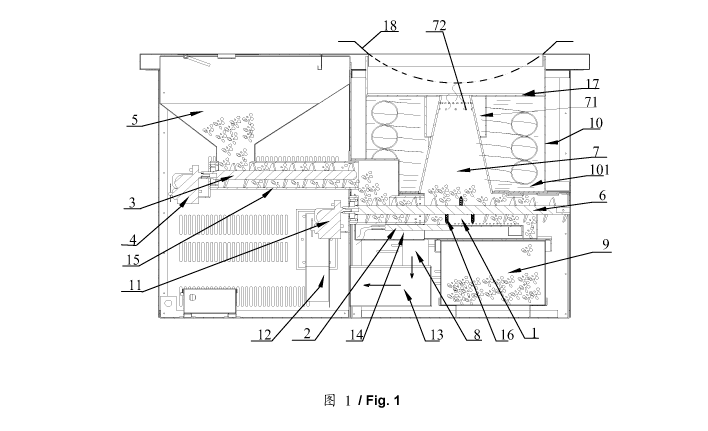
Fig. 1 is a schematic plane view of the preferred embodiment of the invention.
DETAILED DESCRIPTION OF THE INVENTION
An anti-scorification oven is provided in order to prevent scorification after
combustion.
The preferred embodiment of the oven of the invention has an ignition bar 2, a
combustion chamber 1, a first feed rotor 6, a first motor 11, a hopper 5, a
second feed
rotor 3, a second motor 4, and a hearth 7.
The ignition bar 2 is provided in the combustion chamber 1 and for igniting
fuels entered
in the combustion chamber 1. The first feed rotor 6 is provided in the
combustion
chamber 1 and has one spiral sector at each end thereof. A plurality of
scorification
breaking nails 16 are formed in a middle of the first feed rotor 6. The first
feed rotor 6 has
one end passing through a feed inlet of the combustion chamber 1 and the other
end
passing through an ash outlet of the combustion chamber 1. The first motor 11
has an
CA 02824229 2013-06-28
output connected to the first feed rotor 6. The first feed rotor 6 rotates
under a driving
force from the first motor 11. Under a driving force from the spiral sectors,
the fuels enter
the combustion chamber 1 from the feed inlet. The hopper 5 has a feed pipe 15
at a
bottom thereof and in communication with the feed inlet of the combustion
chamber 1.
The second feed rotor 3 is provided in the feed pipe 15. A spiral sector is
provided on the
second feed rotor 3. The end of the second feed rotor 3 at the feed inlet is
higher than the
end of the first feed rotor 6 at the feed inlet.
An output of the second rotor 4 is connected to one end of the second feed
rotor 3 and for
driving the second feed rotor 3 to rotate. Fuel is thus conveyed into the
inlet of the
combustion chamber 1 from the hopper 5.
The hearth 7 is above and in communication with the combustion chamber 1. High
temperature gas and flame from the combustion in the combustion chamber 1
enter the
hearth 7 and then exit the hearth 7 through a top thereof, from which an
object 18 on a
top plate 17 of the hearth 7 will be heated.
The inlet of the combustion chamber 1 is in communication with a branch 14 of
the oven.
The branch 14 is for supplying air to the combustion chamber 1 to support the
burning of
the fuel in the combustion chamber 1.
A process of working of the anti-scorification oven of the invention is as
follows.
CA 02824229 2013-06-28
Driven by the second motor 4, the second feed rotor 3 conveys the fuel in the
hopper 5 to
the inlet of the combustion chamber 1 via the feed pipe 15. The first motor 11
drives the
first feed rotor 6 to send the fuel on the inlet of the combustion chamber 1
to the
combustion chamber 1. Air is supplied through the branch 14. The fuel burns in
the
combustion chamber 1 and the high temperature gas and flame produced will heat
the
object 18 placed on the top plate 17 through the hearth 7. In the process of
burning, ash
produced thereby will be pushed by the fuel newly entering the combustion
chamber 1 to
move towards the ash exit. The ash will be pushed to leave the ash exit by the
first feed
rotor 6. And in this process, the scorification breaking nails 16 rotate with
the first feed
rotor 6 and stir the ash in the combustion. The ash is stirred up and
pulpified, and
scorification of the ash is then prevented.
In the process of working of the oven of the invention, on one hand ash is
stirred up in the
process of combustion to prevent scorification in a circumstance of high
temperature, and
the ash is pulpified by the anti-scorification nails 16 to ensure a complete
combustion of
the incomplete combustion ash. And on the other hand, the ash is pushed to
move by
newly entering fuel and exit the outlet by the push of the first feed rotor 6.
The
scorification caused by long time accumulation of ash in the combustion
chamber 1 is
then avoided. For the preferred embodiment, a phenomenon of scorification in
the
process of combustion is prevented and a lot a biomass fuel such as straw,
sawdust, bark,
and crop stalks will be able to be used as fuel.
CA 02824229 2013-06-28
In the preferred embodiment of the anti-scorification oven, the inlet of the
second feed
rotor 3 near the combustion chamber 1 is higher than the end of the first feed
rotor 6 near
the inlet. There are many kinds of relationship between the positions of the
first and the
second feed rotors 6, 3. Preferably, the first feed rotor 6 is parallel to the
second feed
rotor 3, and the second feed rotor 3 is higher than the first feed rotor 6.
In this preferred embodiment, the anti-scorification nails 16 are provided in
the middle
portion of the first feed rotor 6, i.e., in the middle of the combustion
chamber 1. Points of
all anti-scorification nails 16 are facing outward with respect to the first
feed rotor 6. As
the first feed rotor 6 rotates, the anti-scorification nails 16 stir up and
pulpify the ash in
the combustion chamber 1 to prevent scorification. As a preferred resolution,
all the anti-
scorification nails 16 are in perpendicular with respect to an axil of the
first feed rotor 6.
And as a more preferred resolution, the anti-scorification nails 16 are
staggerly
distributed in the middle of the first feed rotor 6.
In the process of working, the anti-scorification oven of the invention keeps
discharging
ash to the exit of the combustion chamber 1. In order to conveniently collect
ash, an ash
tray 9 is provided under the exit of the combustion chamber 1.
As a preferred resolution, the ignition bar 2 is disposed under a bottom of
the combustion
chamber 1 near the feed inlet thereof. In this dispose, the fuel is able to be
ignited as soon
as it enters the combustion chamber 1.
CA 02824229 2013-06-28
In this preferred embodiment, the hearth 7 is conical and an end having a
smaller cross-
sectional area is an upper side. The upper side of the hearth 7 is connected
to the top plate
17 of the hearth 7. The conical shape of the hearth is able to make the flame
more
concentrated, and a heating efficiency to the object 18 on the top plate 17 is
increased. As
a more preferred resolution, a plurality of air supply holes 72 are defined in
a wall of the
hearth 7. An air supply chamber 71 is formed on an outside surface of the
hearth 7
surrounding the air supply holes 72. An air supply pipe (not shown) is
provided
connecting an inlet of the air supply holes 72 and the branch 14. Air is
supplied into the
air supply chamber 71 via the air supply pipe, and then enters the hearth 7
through the air
supply holes 72. The supply of air to the hearth 7, on one hand, is able to
make the
incompletely burned gas (such as carbon monoxide) to combust completely to
increase
combustion efficiency. On the other hand, less incompletely burned gas will be
discharged into atmosphere. The dispose of the air supply holes 72 is able to
further focus
the flame in the hearth 7. A temperature of the flame is thus enhanced and the
heating
efficiency to the object 18 on the top plate 17 is able to be further
increased.
As a preferred resolution, the air supply chamber 71 is circular and
surrounding a top
portion of the hearth 7. The air supply holes 72 are disposed on the top of
the hearth 7.
Air is supplied into the hearth 7 from a variety of directions. The air supply
is able to
become more replenish and the efficiency may be increased.
In this preferred embodiment of the anti-scorification oven, a tank wall 10 is
provided
surrounding the hearth 7. A boiling water tank 101 is defined by the tank wall
10 and an
CA 02824229 2013-06-28
outer surface of the hearth 7. Water is able to be poured into the boiling
water tank 101 to
absorb heat from the hearth 7. The use ratio of heat of the oven is increased.
As a more
preferred resolution, the air supply pipe goes through the boiling water tank
101. The
boiling water tank 101 is able to pre-heat the air supply pipe. When a
temperature of the
supplying air in the air supply pipe becomes higher, the combustion in the
hearth 7 is able
to be much more improved.
The afore-mentioned boiling water tank 101 is able to absorb and re-use the
heat giving
out from the outer surface of the hearth 7. The heated water is ready for
daily use, such as
bathing, and room heating.
In the above embodiment, only the heat sent out from the outer surface of the
hearth 7 is
re-used. In the working process of the oven, smoke leaving a smoke exit in the
top plate
17 still has a high temperature after passing the object 18. Such emission of
smoke still
causes waste of a lot un-used heat. So, a chimney 8 is provided in
communication with
the smoke exit and passing across the boiling water tank 101. The smoke
exchanges heat
with the water in the boiling water tank 101 via the chimney 8 and the heat
therein will be
able to be re-used. There are different ways of deployment for the chimney 8
to pass
across the boiling water tank 101. In order to increase heat exchanging area,
the chimney
8 goes spirally across the boiling water tank 101 around the hearth 7. As a
more preferred
resolution, a plurality of heat emission fins (not shown) are formed on the
chimney 8,
which will further increase the heating exchanging area.
CA 02824229 2013-06-28
In this preferred embodiment, an exhaust blower 12 is provided at an exit of
the chimney
8. A dust collection box 13 may be provided between the chimney 8 and the
exhaust
blower 12. A plurality of layers of dust collection nets (not shown) are
placed in the dust
collection box 13. There are lot of dust in the smoke going out from the
chimney 8. The
dust must be collected by the dust collection nets in the dust collection box
13 before
entering the exhaust blower 12. The dust collection box 13 is able to be
processed termly
to remove the dust being collected. The disposition of the dust collection box
13 is able to
diminish pollution to the atmosphere from the smoke exiting from the chimney
8.
In this embodiment, the hopper 5 is for containing the fuel and may be of any
shape.
Preferably, the hopper 5 is of cone shape. In a process of fuel feeding, fuel
is able to
automatically fall to the exit of the hopper 5 under gravity and then be
driven by the
second feed rotor 3.
From above description, it is seen that the objects of the present invention
have been fully
and effectively accomplished. Embodiment of the invention has been shown and
described for the purposes of illustrating the functional and structural
principles of the
present invention and is subject to change without departure from the
invention's
principles. Therefore, this invention includes all modifications encompassed
within the
spirit and scope of the following claims.