Note: Descriptions are shown in the official language in which they were submitted.
CA 02829545 2013-10-15
SPEC04-4CA
1
Total Internal Reflection Fluorescence (TIRF) Microscopy Across Multiple
Wavelengths
Simultaneously
TECHNICAL FIELD
[0001] The technology relates to fluorescence microscopy and, in particular,
to systems for
multi-wavelength evanescent illumination of a sample in total intemal
reflection fluorescence
(TIRF) microscopy.
BACKGROUND
[0002] Many different techniques have been developed in the field of
fluorescence
microscopy to restrict excitation light to a thin region of a specimen near
the coverslip in order
to improve the signal-to-background noise ratio and the spatial resolution of
the specimen
features or components of interest. Conventional widefield and laser scanning
confocal
fluorescence microscopy are widely employed techniques that rely on
illumination of
fluorophore-labeled specimens with a broad cone of light. The limited spatial
resolution
demonstrated by widefield fluorescence microscopy, especially along the
optical axis, often
renders it difficult to differentiate between individual specimen details that
are overpowered
by background fluorescence from outside the focal plane.
[0003] In contrast, total internal reflection fluorescence (TIRF) microscopy
employs the
unique properties of an induced evanescent wave to selectively illuminate and
excite
fluorophores in a restricted specimen region immediately adjacent to a glass-
water (or glass-
buffer) interface between the specimen and a transparent substrate.
[0004] The basic concept of total internal reflection fluorescence (TIRF)
microscopy is
simple, requiring only an excitation light beam traveling at a high incident
angle through the
solid glass coverslip or dish, where the cells adhere.
[0005] Figure 1 illustrates an example of the basic concept of TIRF
microscopy. Illumination
light 100 is transmitted into a substrate 102, such as a coverslip, a
coverplate or a slide. The
illumination light 100 strikes an interface 104 between the substrate 102 and
a specimen or
sample 106 to be imaged at a nonzero angle of incidence 108 with respect to
the interface
normal. When the refractive index n2 of the specimen 106 is lower than the
refractive index ni
of the substrate 102, that is n2 (n1, and when the angle of incidence 108 is
greater than or
CA 02829545 2013-10-15
SPEC04-4CA
2
equal to the critical angle of the interface 104, with respect to the
interface normal, the light
experiences total intemal reflection. Thus, none of the illumination light 100
can pass into the
specimen 106 and all of the illumination light 100 is reflected back into the
substrate 102.
However, the reflected light generates an evanescent wave with the same
wavelength as the
illumination light 100. The electromagnetic field of the evanescent wave
penetrates beyond the
interface 104 into the specimen 106 and excites fluorescence within a thin
region of the
specimen 106 near the interface 104. The intensity I of the evanescent field
decays
exponentially with increasing perpendicular distance z from the interface 104,
as illustrated in
Figure 1 and as described by equation 1:
-z
[0006] I(z) =I(0)eki (1)
[0007] where I(z) represents the intensity at a perpendicular distance z from
the interface
104, where 1(0) represents the intensity at the interface 104, and where d
represents the
characteristic penetration depth at a wavelength 7L of incident light in a
vacuum. The
characteristic penetration depth d is expressed by equation 2:
[0008] d =k/(47t=sqn(n12sin201 ¨ n22)) (2)
[0009] Typical penetration depths are only about 100 nanometers from the
interface 104, as
represented by the dashed line 112 in Figure 1. Fluorophores of fluorescently
labeled
components located within the vicinity of the interface 104 can be excited by
the evanescent
field. A portion of the fluorescent light emitted from fluorophores near the
interface 104 may
be captured by an objective lens and may be used for fluorescent imaging of
the specimen 106.
Accordingly, this technique is useful for studying phenomena near the
interface 104 between
the substrate 102 and the sample 106, since other parts of the sample 106 are
not illuminated at
all.
[0010] Figure 1 illustrates a schematic representation of an objective 114
used to illuminate
the specimen 106 disposed on the substrate 102. The objective 114 is an oil
immersion
objective with immersion oil 116 disposed between the substrate 102 and a top
lens 118 of the
objective 114.
[0011] A common means of achieving objective-based TIRF microscopy is to focus
the
illumination light 100 travelling along an optical axis 115 of the microscope
to a focal point
near the outer edge of the objective 114 and at a back focal plane 120 of the
microscope
objective 114, as illustrated in Figure 1. It should be noted that, although
the back focal plane
=
CA 02829545 2013-10-15
SPEC04-4CA
3
120 is illustrated in a location that is external to the objective 114, it may
alternatively be
located within the objective 114. The objective 114 has a high numerical
aperture (NA) in
order to allow the illumination light 100 to be transmitted near the outer
edges of the lenses of
the objective 114 and directed into the substrate 102 with an angle of
incidence 108 that
supports total internal reflection. The substrate 102 and the immersion oil
116 may have nearly
the same refractive index ni , for example, approximately 1.52, and the
specimen 106 may be
in an aqueous medium with a refractive index n2 of approximately 1.33 to 1.40,
for example,
which supports total internal reflection within the substrate 102. The NA of
the objective 114
is higher than the refractive index n2 of the specimen 106. The illumination
light 100 strikes
the substrate/specimen interface 104 with an angle of incidence 108 greater
than the critical
angle and is reflected back into the substrate 102 at the interface 104. The
illumination light
100 creates in the specimen 106 an evanescent electromagnetic field adjacent
to the interface
104 .
[0012] The radial distance, for example the distance 122 in Figure 1, of the
point of light
from the optical axis 115 of the objective 114 determines the angle that the
light will have
when leaving the objective 114. This, in turn, affects the angle of incidence
108 at the
substrate/sample interface 104. Light focused further from the optical axis
115 will have a
larger angle of incidence 108. By adjusting the position that the light
focuses onto the
objective back focal plane 120, the angle of incidence 108 can be adjusted to
be near or
slightly larger than the critical angle. The degree to which the angle of
incidence 108 is greater
than the critical angle will determine the depth of the evanescent wave and
thus the imaging
depth. These instruments, which use oil-immersion objectives with a high
numerical aperture,
are increasing in popularity today.
[0013] TIRF microscopy is an established microscopy technique with a number of
implementations. Figure 2 illustrates a possible simple TIRF implementation
with a single
mode fiber light delivery subsystem.
[0014] Illumination light from a single mode fiber 200 is collimated using a
lens 202, and
then directed via a lens 204 to a dichroic mirror 206.11lumination light
incident on the dichroic
mirror 206 is focused onto a back aperture 208 of an objective 210 at a
desired radial distance
R 212 from the optical axis 213 of the objective 210. The radial distance R
212 is adjustable
CA 02829545 2013-10-15
SPEC04-4CA
4
by laterally moving optical elements such as the single mode fiber 200 or the
lens 202 or the
lens 204, where the lateral direction is denoted by an arrow 224 in Figure 2.
[0015] The objective 210 directs the illumination light, via a hemispherical
lens 222, through
a substrate 214 and into a sample 216 to be imaged. The illumination light may
strike the
interface between the substrate 214 and the sample 216 with angles of
incidence that are
greater than the critical angle, such that total internal reflection is
achieved.
[0016] Fluorescent light emitted from the sample 216 near the substrate/sample
interface
may be captured by the hemispherical lens 222 of the microscope objective 210
at the
operating numerical aperture NA of the microscope objective 210. The collected
fluorescent
light further passes through the dichroic mirror 206 and is focused by a tube
lens 218 onto an
image plane which coincides with an image sensor of an imaging device 220.
[0017] Varying an incidence angle of the illumination light or a depth along
which
observation should be carried out is usually accomplished in the objective-
based TIRF
microscopy instrument by varying the radial distance of the focused light spot
of the
illumination light at the back focal plane of the microscope objective. The
lateral displacement
can be implemented through any of a plurality of technically simple means. For
example, in
such a microscope, a pick-off member, which reflects the light from a light
source to a sample,
may be placed in the back focal plane. The pick-off member may be in the form
of a small
mirror, as described in JP9159922A. Alternatively, the pick-off member may be
in the form of
a right angle prism, as described in US Patent No. 6,987,609. A displacement
of the pick-off
member in the radial direction away from the optical axis of the objective
leads directly to a
corresponding change in the angle of incidence of the illumination light and
the penetration
depth of the TIRF imaging.
100181 In another example, radial beam displacement may be achieved using
deflection
means such as a steering mirror (as described in JP2002031762) or an acousto-
optical
modulator (as described in US Patent Application Publication No. 20030058530),
in
combination with a focusing lens. The radial beam adjustment may be done by a
lateral
movement of the tip of a light delivering optical fiber, as described in US
Patent No.
6,924,490, or by lateral movement of a focusing lens, as described in US
Patent No.
6,992,820. The TIRF microscope described in US Patent No. 7,224,524 comprises
an optical
device in the form of a wedge plate which is disposed on the optical path of
the optical
illumination system and de-centers an optical axis of the light beam.
CA 02829545 2013-10-15
SPEC04-4CA
SUMMARY
[0019] Objective-based TIRF microscopes present several challenges when
dealing with
multiple wavelength TIRF. For example, multiple wavelength TIRF microscopes
use a
multiple wavelength illumination beam directed along the outer edge of the
lenses of the
objective. However, because the critical angle is invariably wavelength
dependent, differing
wavelengths will have different angles of incidence. This can mean that some
wavelengths of
light will be totally internally reflected, while others will not be totally
internally reflected. It
can also mean that different wavelengths will image to differing depths within
the sample.
[0020] A typical light source for TIRF microscopy is laser light transmitted
through a single
mode fiber, as described, for example, in US Patent No. 6,819,484, US Patent
No. 6,987,609,
and US Patent No. 6,992,820). However, broadband radiation light sources have
been used
with narrow annular diaphragms, as described in US Patent No. 6,597,499 and US
Patent No.
7,474,462, or with crescent-shaped slits, as described in US Patent No.
7,224,524, where the
annular diaphragms or slits limit the spatial extent of the light in the
radial dimension.
100211 Several solutions have been used to enable imaging across multiple
wavelengths. The
most basic solution is to adjust the position of the incoming light source
such that the radial
distance of the focused light spot at the back focal plane of the objective
can be adjusted
laterally. The adjustment can be done manually or with an automated actuator.
In either case,
simultaneously imaging at multiple wavelengths is compromised, as a single
light source can
only be focused at one location at a time. Often this means sequentially
changing the focus
position with wavelength changes. However, there are disadvantages to
switching between the
different excitation wavelengths by mechanically steering and refocusing the
multiple
wavelength beam so that a selected wavelength strikes the interface with an
angle of incidence
greater than the critical angle for each wavelength. This process takes time,
it prevents
simultaneous imaging with more than one wavelength, and it requires additional
mechanical
systems to change the position of a focal point of the illumination beam in
the objective back
focal plane, which increases the cost of an objective-based TIRF microscope.
[0022] To overcome this shortcoming, Olympus Corporation headquartered in
Tokyo, Japan
has introduced a system called the cellATIRF that uses four fibers that can
be independently
positioned. This allows four different wavelengths to be used simultaneously.
However, it
CA 02829545 2013-10-15
SPEC04-4CA
6
complicates the instrument, the alignment, and the originating light source,
which is often a
multitude of lasers.
[0023] US Patent No. 8,378,314 describes an apparatus that comprises
correction optics
providing a transverse chromatic aberration which is pre-configured in such a
way that the
wavelength-dependent differences of the penetration depth in the evanescent
illumination of
the sample are partially corrected. The chromatic aberration component is
built in the form of
a multi-component lens or an oblique planar plate. US Patent No. 8,378,314
discloses that the
system should be designed to achieve a predetermined chromatic aberration to
account for
an assumed system having a particular microscope objective, particular indices
of refraction of
the oil, the coverslip, and sample, and particular illumination wavelengths. A
well-known
problem with this implementation is that it is rare for all of these factors
to be known a priori.
Accordingly, the system proposed in US Patent No. 8,378,314 may not be
particularly useful
in actual applications where numerous wavelengths are used and sample media
change from
sample to sample.
100241 To address the problems with the state of the art, an adjustment device
may be
designed to distribute the focal spots of multiple light beams of different
wavelengths provided
by a single mode fiber to different radial locations on the back focal plane
of the oil immersion
microscope objective, thus providing desired angles of incidence of the light
onto a
substrate/sample interface and desired depths of the evanescent waves of
different
wavelengths. For these purposes, the adjustment device may comprise a
dispersive unit
providing controlled chromatic dispersion of the multi-wavelength illuminating
light and
splitting the multi-wavelength illuminating light into a set of monochromatic
beams required,
for example, to achieve the same illumination depths for the different
wavelengths used. The
adjustment device may also comprise a beam steering means providing a desired
simultaneous
shift of a whole set of the individual focal points of different wavelengths
without varying the
radial distances between them.
100251 The technology described herein relates to a method and a device for
the evanescent
illumination of a sample for TIRF microscopy, in which the wavelength-related
differences of
the penetration depths can be reduced in a manner that is tunable to the
imaging conditions
presented.
100261 In one example, there is provided an adjustable dispersive device for
the evanescent
illumination of a sample that provides controlled chromatic dispersion ¨ the
relative separation
CA 02829545 2013-10-15
SPEC04-4CA
7
of at least two focal spots in the back focal plane of the objective ¨ of the
illuminating light
using a single dispersive optical flat with a tunable angle of incidence.
Changing the angle of
incidence by rotating the optical flat will change the dispersive effect of
the optical flat. Larger
angles of incidence will correspond to greater lateral separation of optical
beams with differing
wavelengths. In this manner, the difference in radial positions as a function
of wavelength can
be tuned. This tuning can, to some degree, correct for differences in the
critical angle as a
function of wavelengths.
100271 As the optical flat is rotated, not only is the dispersive effect tuned
but the absolute
offset of the optical beam is also varied. In addition, the total path length
through the optical
flat is changed, which in turn changes the axial focal position of the focused
spots near the
back focal plane of the objective. Although, both of these effects can be
corrected by using
other alignment optics, in practice it is inconvenient and difficult to
account for the full range
of adjustment in both lateral and axial dimensions.
[0028] In another example, the shift in axial focus is reduced along with
other optical
aberrations. The adjustment device comprises a dispersive unit in the form of
two optical flats
oriented in a V formation, one flat of a highly dispersive glass and one of a
low dispersion
glass. Such a dispersive unit for the evanescent illumination of a sample that
provides
controlled chromatic dispersion ¨ relative distance between at least two focal
spots in the back
focal plane of the objective ¨ but results in less axial chromatic aberration
and hence less axial
focus shift. This formation also creates fewer optical aberrations, such as
astigmatism or
spherical aberration. In this manner, the corrections required to account for
the focus
displacement may be unnecessary.
[0029] Additional adjustment of the absolute radial locations of the focal
spots of the multi-
wavelength excitation light beams on the back focal plane of the microscope
objective may be
required, for example, when the TIRF microscope is used for imaging a sample
at different
penetration depths, or, alternatively, a number of samples under investigation
having different
refractive indexes.
[0030] The technology described herein may enable multiple wavelengths to be
used
simultaneously with closely matched image TIRF penetration depths.
[0031] R is used herein to denote an absolute radial distance of a focal point
from an optical
axis of an objective at (or near) the back focal plane of the objective.
CA 02829545 2013-10-15
SPEC04-4CA
8
[0032] R(Xi) may be used to denote the distance R for a focal point of a
monochromatic
beam of a first wavelength X. R(X2) may be used to denote the distance R for a
focal point of
a monochromatic beam of a second wavelength X2. Some implementations of the
dispersion
unit may provide positive dispersion of the multi-wavelength excitation light
when R(X 1) >
R(X2), X1 >1.2, and negative dispersion when R(Xi) <R(X2), X1 The
dispersion unit may be
used for obtaining closely matched image TIRF penetration depths for a whole
range of
desired penetration depths, for example, from approximately 100 nm to 200 ¨
300 nm. The
dispersion unit may also be used for a plurality of objective-sample
combinations.
[0033] Some implementations of the controllable dispersive unit for the
evanescent
illumination of a sample may show low undesired optical aberrations.
100341 Rotation of the dispersion unit may allow the user to tune the relative
penetration
depths for illumination light of different wavelengths in order to achieve
depths that are as
similar as possible. This may be done without knowledge of the optical
properties of
microscope, objective, sample or substrate. By using a sample with defined
structure, such as
small beads, the angle of the dispersion unit may be tuned to closely match
the imaging depth
across a number of wavelengths.
[0035] The terms "light" and "radiation" may be used interchangeably and refer
to light in
the UV-visible-NIR (ultraviolet-visible-near infrared) spectral range. The
terms "light source"
and "radiation source" may refer to any source able to generate and emit light
or radiation,
including but not limited to, lasers, light emitting diodes (LEDs), solid
state devices, super
luminescent diodes (SLDs), arc lamps, or any other suitable light sources as
would be apparent
to someone skilled in the art.
100361 "Illumination light" or "excitation light", as used herein, refers to
any light provided
by a light source to be used for evanescent illumination of a sample.
"Emission light" or
"returned light" refers to the light returning from the sample, and used for
obtaining images of
the sample. The returned light is often produced by fluorescence of a sample
illuminated with
the excitation light.
[0037] A "reference wavelength", as used herein, refers to one of wavelengths
of the
multiple wavelength illumination light. For the sake of definiteness, the
shortest wavelength
may be taken as the reference wavelength.
CA 02829545 2013-10-15
SPEC04-4CA
9
[0038] The term "evanescent illumination" or "total internal illumination", as
used herein,
refers to the illumination light which is incident on the interface between a
substrate and a
sample at an angle of incidence that is greater than or equal to the critical
angle of reflection.
At these angles, all light is reflected but the electromagnetic field of the
evanescent wave
produced by the illumination light is available at small depths in the sample,
thus providing
excitation of fluorescence within a thin region of the sample near the
interface.
[0039] An "optical path length (OPL)" or "optical distance", as used herein,
refers to a sum
of the products of the geometric lengths of the paths that light follows
through optical
components and/or media, and the respective indices of refraction of those
optical components
and/or media. A difference between two optical path lengths is called an
optical path
difference (OPD).
[0040] As used herein, a "microscope" comprises at least a microscope
objective lens, as
illustrated, for example, by the objective 114 in Figure 1, and by the
objective lens 210 in
Figure 2. In other examples, microscopes may be considered to have the more
conventional
form of an infinity corrected micro-objective and a tube lens. Both cases are
interchangeable.
A "microscope system" is a system that may be used to probe a sample by
providing an
evanescent illumination of the sample, thus producing fluorescence light from
the sample.
CA 02829545 2013-10-15
SPEC04-4CA
BRIEF DESCRIPTION OF THE DRAWINGS
[0041] Figure 1 illustrates the operational principle of objective based TIRF
microscopy
according to prior art.
[0042] Figure 2 illustrates a schematic view of a single wavelength objective
based TIRF
microscope according to prior art.
[0043] Figure 3 illustrates a schematic view of an example TIRF microscopy
system for
multi-wavelength evanescent illumination of a sample.
[0044] Figures 4-1 and 4-2 illustrate magnified views of the dispersion unit
of the objective-
based TIRF microscopy system of Figure 3.
[0045] Figure 5 illustrates a magnified view of the objective lens with the
sample in the
objective-based TIRF microscopy system of Figure 3.
[0046] Figure 6 illustrates a schematic view of another example TIRF
microscopy system for
multi-wavelength evanescent illumination of a sample.
[0047] Figures 7-1, 7-2, and 7-3 illustrate magnified views of the dispersion
unit of the
objective-based TIRF microscopy system of Figure 6.
[0048] Figure 8 illustrates a magnified view of the objective lens with the
sample in the
objective-based TIRF microscopy system of Figure 6.
[0049] It will be appreciated that for the simplicity and clarity of
illustration, elements shown
in the figures have not necessarily been drawn to scale. For example, the
dimensions of some
of the elements may be exaggerated relative to other elements for clarity
purposes.
CA 02829545 2013-10-15
SPEC04-4CA
11
DETAILED DESCRIPTION
[0050] Figure 3 illustrates a schematic representation of an example objective-
based multiple
wavelength TIRF microscopy system 300.
[0051] The system 300 includes a microscope 302 comprising a high numerical
aperture oil
immersion objective 304 with a back focal plane 306 and a hemispherical top
lens 308. It
should be noted that although the back focal plane 306 is illustrated in a
location that is
external to the objective 304, the back focal plane 306 may alternatively be
located within the
objective 304. The lens 308 is placed into contact with immersion oil 310,
which in turn is
placed into contact with a substrate 312, such as a coverslip. The substrate
312 contacts a
sample 314 at a substrate/sample interface 316.
[0052] The system 300 includes an illumination module 320 configured to
provide a beam of
illumination light of at least two different wavelengths. The illumination
module 320
comprises a light source 322. In one example, the light source 322 is in the
form of the multi-
wavelength radiation source assembly described in US Patent No. 8,275,226,
which is
configured to generate and optionally to condition multi-wavelength radiation
that is suitable
for illumination in TIRF microscopy. Depending on the application, the light
source 322 may
comprise two or more lasers, each laser generating light at a different
wavelength, for
example.
[0053] For the sake of simplicity and brevity in the following description,
the illumination
light is composed of a mixture of at least two wavelengths: a first wavelength
Xi (also known
as the reference wavelength) and a second wavelength X2, where the wavelength
Xi is shorter
than the wavelength X2.
[0054] The light source 322 may be coupled to a fiber optic light delivery
subsystem, which
may include one or more lenses (not shown), one or more mirrors (not shown),
and/or one or
more prisms (not shown). The fiber optic light delivery subsystem is
illustrated in Figure 3 in
the form of a single mode optical fiber 324. A distal end tip 326 of the
optical fiber 324 may
be mounted in a plane 328 that is conjugate to the back focal plane 306 of the
objective 304.
CA 02829545 2013-10-15
SPEC04-4CA
12
100551 The optical fiber 324 has a numerical aperture NAF, which is related to
the half-angle
OF 333 illustrated in Figure 3. In general, a numerical aperture NAF of a
fiber is expressed by
equation 3 as:
[0056] NAF =nsinOF (3)
[0057] where n is a refractive index of the surrounding medium to which the
light exits from
the distal end 326 of the fiber 324, and the exit angle OF is the angle of
divergence of light
with respect to an optical axis 330 of the fiber 324. In the case that the
surrounding medium is
air, the refractive index n = 1. Common values for the numerical aperture NAF
of a single
mode fiber range from 0.10 to 0.15, and, for visual light, NAF =--, 0.12 -
0.13.
[0058] In order to collimate the light beam emerging from the fiber tip 326, a
collimating
lens 334 having a focal length F334 may be placed at an optical distance F334
from the fiber
tip 326.
[0059] An imaging lens 336 having a focal length F336 may be used to focus the
previously
collimated beam emerging from the collimating lens 334 onto the back focal
plane 306 of the
objective 304, via a dichroic mirror 338. The light may also be reflected off
of an optional
folding mirror (not shown). For superior system performance, the imaging lens
336 may be
placed at an optical distance F336 from the collimating lens 334. The lenses
334 and 336 form
a relay optical device providing an image of the fiber tip 326 onto the back
focal plane 306.
[0060] The system 300 includes an imaging module 340 which comprises an
imaging device
342, such as a high-sensitivity camera, and an optional blocking filter 348.
The imaging device
342 comprises an image sensor 344, and may be positioned such that a front
face of the image
sensor 344 coincides with an image plane 346 that is conjugate to a sample
plane adjacent to
the substrate/sample interface 316.
[0061] A non-exhaustive list of examples of the imaging device 342 includes a
charge-
coupled device (CCD) camera, a complementary metal-oxide semiconductor (CMOS)
camera,
an intensified CCD (ICCD) camera, and any other suitable camera as would be
apparent to
someone skilled in the art. A 3CCD camera with additional narrowband filters
may be applied
for simultaneous multi-spectral imaging. Alternatively, the emission light may
be split using
SPEC04-4CA
13
dichroic mirrors to simultaneously image different wavelength bands on
separate imaging
devices.
[0062] Fluorescent light emitted from the sample 314 near the interface 316
may be captured
by the hemispherical lens 308 of the microscope objective 304 at thc operating
numerical
aperture of the microscope objective 304. The collected fluorescent light
further passes
through the dichroic mirror 338 and the optional blocking filter 348, and is
focused by a lens
349 onto the image plane 346 coinciding with a detection plane of the image
sensor 344 of the
imaging device 342, where it may be captured.
[0063] The system 300 includes a dispersion unit 350 which will be described
in more detail
below.
[0064] To improve operation of the system 300 and to decrease spherical
aberration and
astigmatism induced by the dispersion unit 350, it may be of interest to lower
the numerical
aperture of the illumination beam exiting the fiber tip 326. This may be
achieved by placing
optional light divergence control optics 332 at a predetermined distance from
the fiber tip 326.
[0065] In one example, a desired beam aperture may be obtained by placing, at
a distance
Z326 from the fiber tip 326, light divergence control optics 332 in the form
of an achromatic
lens having a focal length F332 and a numerical aperture NA332. The distance
Z326 from the
fiber tip 326 may be found by using the thin lens approximation and paraxial
approximation,
and is expressed in equation 4 as:
[0066] Z326 = F332(1-NAFINA332) (4)
[00671 The collimating lens 334 may be placed at a predetermined optical
distance Z332
from the lens 332, where the distance Z332 may be found by using the thin lens
approximation
and paraxial approximation, and is expressed in equation 5 as:
[0068] Z332 = F334 = F332(NA332/NAF ¨ 1) (5)
[0069] While the divergence control optics 332, the collimating optics 334,
and the imaging
optics 336 are presented in the form of achromatic doublet lenses, they may
alternatively be
built in the form of aspherized achromatic, gradient index, triplet, or multi-
component lenses,
or any other focusing elements, including reflective focusing elements, as
would be apparent
to someone skilled in the art.
CA 2829545 2017-10-27
CA 02829545 2013-10-15
SPEC04-4CA
14
[0070] The dispersion unit 350 may be designed to distribute the focal spots
of at least two
light beams of at least two different wavelengths originating from the fiber
tip 326 to at least
two different radial locations on the back focal plane 306 of the high
numerical aperture
objective 304, thereby providing desired angles of incidence of the light onto
a
substrate/sample interface 316 and desired depths of the evanescent waves of
illumination
light of the at least two different wavelengths. The dispersion unit 350
provides controlled
chromatic dispersion of the illuminating light of at least two different
wavelengths and
splitting the at least two-wavelength light into at least two monochromatic
beams required, for
example, to achieve the same illumination depths for the different wavelengths
used. The
dispersion unit 350 may also comprise a beam shifting means (not shown)
providing a desired
simultaneous absolute offset of a whole set of the at least two individual
focal points of
different wavelengths without varying the radial distances between them.
[0071] The dispersion unit 350 may be configured to provide controlled
chromatic dispersion
of illuminating light of at least two different wavelengths. The dispersion
unit 350 may be
implemented in the form of a single optical flat 354 which may be mounted on a
rotatable
plate 356. The rotatable plate 356 is rotatable about an axis perpendicular to
the plane of the
rotatable plate 356.
[0072] Figures 4-1 and 4-2 illustrate the example dispersion unit 350 in
different
orientations.
[0073] a 362 represents an angle of the normal of the optical flat 354
relative to the optical
axis 330. The direction of rotation of the rotatable plate 356 is denoted by
the arrow 355.
[0074] In Figure 4-1, the dispersion unit 350 is in its central position such
that the angle a
362 is zero. In Figure 4-2, the dispersion unit 350 is oriented such that the
angle a 362 is
greater than zero.
[0075] The optical flat 354 is a highly dispersive optical element. In one
example, the optical
flat 354 may be made of optical glass SF11 or of optical glass SF10. The
dispersion of the
optical flat 354 leads to a distance between chief rays s354(n,a) of at least
two beams with
different wavelengths Xj and X2, expressed by equation 6 as:
,
[0076] s3540354, n354, a) =t354sina(cosa=An354/03542 ¨ sin2,3/2) (6)
[0077] where t354 is the thickness of the optical flat 354, and n354 is an
average index of
refraction which may be found using equation 7:
CA 02829545 2013-10-15
SPEC04-4CA
[0078] 11354 =[n354(?q) +n354(k2)]/2 =N354 - An354 /2 (7)
[0079] where An354 =n354(k1) ¨ n354(X2), and where N354 =n354(1).
[0080] In general, NK =nK(Xi) may be used herein to represent the refractive
index of the
optical flat K at the reference wavelength k , where Xi <X2.
[0081] The absolute offset y354 provided by the optical flat 354 is expressed
by equation 8
for the reference wavelength Xi as:
2 2 õ
[0082] y354(t354, n354, a) =t354sina(1 - cosoc/sqrt(n354 ¨ sin a)) (8)
[0083] The absolute offset y354 is denoted by 402 in Figure 4-2.
[0084] By rotating the single-plate dispersion unit 350, a range of offsets
may be provided
for the at least two beams of different wavelengths.
[0085] Adjustment of the absolute offset and compensation of the undesired
absolute offset
may be achieved by simultaneous radial shift of the at least two individual
focal points of
different wavelengths provided by means of lateral movement of the distal tip
326 of the
single mode fiber 324, where the lateral direction is denoted by arrow 224.
[0086] Alternatively, compensation of the absolute lateral offset may be
achieved by means
of lateral movement of the collimating lens 334.
[0087] In another example, compensation of the absolute lateral offset may be
achieved by
means of lateral movement of the imaging lens 336.
[0088] In another example, compensation of the absolute lateral offset may be
achieved by
means of movement of the dichroic mirror 338 along an optical axis 364 of the
microscope
module 302 or along the optical axis 330 or along both.
[0089] In another example, compensation of the absolute lateral offset may be
achieved by
using any other suitable beam shifting means providing a desired simultaneous
radial shift of
the at least two individual focal points, as would be apparent to someone
skilled in the art. The
beam shifting means may be part of the dispersion unit 350.
[0090] In yet another example, compensation of the absolute lateral offset may
be achieved
by means of steering an optional folding and steering mirror (not shown) or
any other beam
steering means placed between the collimating lens 334 and the imaging lens
336, as would be
apparent to someone skilled in the art.
CA 02829545 2013-10-15
SPEC04-4CA
16
100911 In practice, a single lens or more than the two lenses 334 and 336 and
additional
mirrors may be used to direct and control the path of light output from the
tip 326 of the fiber
324 and to input the light to the objective 304.
[0092] IN OPERATION: Illumination light of at least two different wavelengths,
Xj and X2,
is delivered from the light source 322 through the single mode optical fiber
324. The light
diverges or spreads out from the distal end 326 of the fiber 324, and passes
through the
optional divergence control lens 332 and through the optical flat 354 of the
dispersion unit
350.
[0093] The illumination light is split by the optical flat 354 into at least
two beams of
different wavelengths, X1 and X2, with a distance between chief rays
s354(t354, n354, a) given
by equation 6, and an offset y354 given by equation 8. The absolute offset of
the at least two
beams of different wavelengths may be compensated, for example, by means of
lateral
movement of the distal tip 326 of the fiber 324. After passing through the
dispersion unit 350,
the chief rays parallel to the optical axis 330 pass through the collimating
lens 334. The light is
collimated by the collimating lens 334, which provides at least two collateral
partially
overlapping collimated beams travelling toward the imaging lens 336. The light
is refocused
by the imaging lens 336 before being reflected by the dichroic mirror 338
along the optical
axis 364 and toward the outer edge of the back focal plane of the microscope
objective 304.
[0094] The imaging lens 336 focuses the illumination beams onto (or close to)
the back focal
plane 306 of the objective 304, so that the lenses 334 and 336 provide an
image of the fiber tip
326 onto the back focal plane 306.
[0095] The relative distance AR between the two focal points of the different
wavelengths,
X1 and X2, is illustrated at 500 in Figure 5 and is expressed by equation 9
as:
[0096] AR =y354- F336/F334 (9)
[0097] The objective 304 directs the beams of illumination light travelling
along the outer
edge of the objective lenses of the objective 304 so that light exiting the
hemispherical lens
308 and passed through the immersion oil 310 and the substrate 312 strikes the
interface 316
between the sample 314 and the substrate 312 with angles of incidence that are
greater than
the critical angle and provide the desired depths of the evanescent waves of
illumination light
of the at least two different wavelengths.
CA 02829545 2013-10-15
SPEC04-4CA
17
100981 The objective 304 has a high numerical aperture NA in order to allow
the at least two
beams of illumination light of different wavelengths Xi and focused
separately onto (or
close to) the back focal plane 306, to be transmitted near the outer edge of
the microscope
objective 304 and directed into the substrate 312 with an angle of incidence
that supports total
internal reflection. The at least two-wavelength light may be present
simultaneously or one at
a time or in any combination of wavelengths simultaneously. For aqueous
mounts, the
refractive index n2 of the sample 314 may be greater than 1.33, that is n2 >
1.33. In one
example, the substrate 312 and the oil 310 have nearly the same refractive
index ni of
approximately 1.52, and the sample 314 is in an aqueous medium with a
refractive index n2 of
approximately 1.33-1.40. This supports total internal reflection on the
substrate/sample
interface 316. The numerical aperture NA of the microscope objective 304 is
higher than the
refractive index n2 of the sample.
100991 Rotation of the dispersion unit 350 and lateral shifting of the fiber
tip 326 may allow
the user to adjust the radial locations R of the focal spots of at least two
converging
monochromatic light beams of two different wavelengths on (or near) the back
focal plane
306. As a result, it is possible to tune the relative penetration depths of
evanescent illumination
light of different wavelengths, for example, to obtain depths that are as
similar as possible for
different wavelengths.
1001001 Additional adjustment of the radial locations R of the focal spots of
the at least two
different wavelengths on (or near) the back focal plane 306 may be of
interest, for example,
when seeking to image a sample at different penetration depths, or,
alternatively, when
imaging a number of different samples having different refractive indexes.
1001011 Fluorescent light emitted from the sample 314 near the interface 316
may be captured
by the hemispherical lens 308 of the microscope objective 304 at the operating
numerical
aperture NA of the microscope objective 304. The collected fluorescent light
further passes
through the dichroic mirror 338 and the blocking filter 348, and is focused by
the lens 349
onto the image plane 346, which coincides with a detection plane of the image
sensor 344 of
the imaging device 342. The collected fluorescent light may alternatively be
separated into
different wavelength ranges and simultaneously imaged on multiple imaging
devices as would
be apparent to one skilled in the art.
CA 02829545 2013-10-15
SPEC04-4CA
18
[00102] When the optical flat 354 is set to an angle other than normal
incidence to the optical
axis 330, as illustrated in Figure 4-2 for example, aberrations, such as
astigmatism, may occur
at the back focal plane 306 of the objective 304.
[00103] In addition, the presence of the optical flat 354 when angled relative
to the
illumination beam may cause the focal points to shift away from the back focal
plane 306
along the axis 364. This is described in more detail with respect to Figure 5.
[00104] Figure 5 illustrates a magnified view of the objective 304 with the
sample 314 in the
objective-based TIRF microscope system 300 of Figure 3.
[00105] As described previously, the system 300 provides illumination of the
sample 314,
which is disposed on the substrate 312. The objective 304 is an oil immersion
objective with
immersion oil 310 disposed between the substrate 312 and the hemispherical
lens 308 of the
objective 304.
[00106] The presence of the optical flat 354 may cause the locations of the
focal points of the
illumination beams having wavelengths Xi and X2 to shift in a direction
parallel to the optical
axis 364. This is illustrated schematically in Figure 5 by the distances 502
and 504, which
represent the respective axial shifts of the monochromatic beams for
wavelengths Xi and 2,.2
relative to the back focal plane 306.
[00107] To address the aberrations and/or axial shifting of the focal spots
relative to the back
focal plane, a second optical flat may be added to the dispersion unit. The
second optical flat
has a lower index of refraction than the first optical flat.
[00108] The second optical flat may be inserted into the optical beam path at
an angle relative
to the first optical flat. In one example, a normal of the first optical flat
and a normal of the
second optical flat have an angle of 300 between them. The two optical flats
may be fixed or
mounted to a rotatable plate or platform such that, as the first optical flat
rotates about an axis
by some angular amount, the second optical flat rotates about the axis by the
same angular
amount.
[00109] The second optical flat may be angled with respect to the first
optical flat to reduce
any aberrations, such as astigmatism, that occur at the back focal plane of
the objective lens.
[00110] A thickness of the second optical flat may be selected such that the
optical path length
of the illumination beams is almost the same regardless of what angle the pair
of optical flats
is rotated by, thereby minimizing the amount of axial focus change at the back-
focal plane of
CA 02829545 2013-10-15
SPEC04-4CA
19
the objective. In one example, the pair of optical flats may be rotated
between a minimum of
00 and a maximum of 300.
[00111] With the thickness and the index of refraction of the first optical
flat fixed, and the
refractive index of the second optical flat fixed, the thickness of the second
optical flat may be
selected by solving a mathematical expression that matches the optical path
lengths for the two
angular extremes, such as 0 and 30 . For intermediate angular positions, the
optical path
length may be nearly maintained with this thickness.
[00112] The precise axial spacing between the two optical flats should be
small enough to
ensure that the illumination beams pass fully through both faces of the
optical flats at all
angular positions without clipping on the optical flat edges. This also
applies for the lateral
size and dimensions of the optical flats.
[00113] Figure 6 illustrates a schematic representation of an example
objective-based multiple
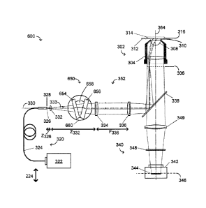
wavelength TIRF microscopy system 600.
[00114] The example TIRF microscopy system 600 includes a dispersion unit 650.
[00115] As described previously with respect to Figure 3, illumination light
of at least two
different wavelengths, Xi and X,2, is delivered from the light source 322
through the single
mode optical fiber 324. The light diverges or spreads out from the distal end
326 of the fiber
324, and passes through the optional divergence control lens 332.
[001161 The light from the imaging lens 336 is incident on the dispersion unit
650.
[00117] The light exiting the dispersion unit 650 is collimated by the
collimating lens 334,
and then refocused by the imaging lens 336.
[00118] The light is then reflected by the dichroic mirror 338 along the
optical axis 364 and
toward the outer edge of the back focal plane of the microscope objective 304.
The imaging
lens 336 focuses the illumination beams onto the back focal plane 306 of the
objective 304, so
that the lenses 334 and 336 provide an image of the fiber tip 326 onto the
back focal plane
306.
[00119] As described previously with respect to Figure 3, fluorescent light
emitted from the
sample 314 near the interface 316 may be captured by the hemispherical lens
308 of the
microscope objective 304 at the operating numerical aperture NA of the
microscope objective
304. The collected fluorescent light further passes through the dichroic
mirror 338 and the
blocking filter 348, and is focused by the lens 349 onto the image plane 346,
which coincides
CA 02829545 2013-10-15
SPEC04-4CA
with a detection plane of the image sensor 344 of the imaging device 342. The
collected
fluorescent light may alternatively be separated into different wavelength
ranges and
simultaneously imaged on multiple imaging devices as would be apparent to one
skilled in the
art.
[00120] Similarly to the system 300, to improve operation of the system 600
and to decrease
spherical aberration and astigmatism induced by the dispersion unit 650, it
may be of interest
to lower the numerical aperture of the illumination beam exiting the fiber tip
326. This may be
achieved by placing optional light divergence control optics 332 at a
predetermined distance
from the fiber tip 326.
[00121] Similarly to the dispersion unit 350, the dispersion unit 650 may be
designed to
distribute the focal spots of at least two light beams of at least two
different wavelengths
originating from the fiber tip 326 to at least two different radial locations
on the back focal
plane 306 of the high numerical aperture objective 304, thereby providing
desired angles of
incidence of the light onto a substrate/sample interface 316 and desired
depths of the
evanescent waves of illumination light of the at least two different
wavelengths. The
dispersion unit 650 provides controlled chromatic dispersion of the
illuminating light of at
least two different wavelengths and splitting the at least two-wavelength
light into at least two
monochromatic beams required, for example, to achieve the same illumination
depths for the
different wavelengths used. The at least two-wavelength light may be present
simultaneously
or one at a time or in any combination of wavelengths simultaneously. The
dispersion unit 650
may also comprise a beam shifting means (not shown) providing a desired
simultaneous
absolute offset of a whole set of the at least two individual focal points of
different
wavelengths without varying the radial distances between them.
[00122] The dispersion unit 650 may be configured to provide controlled
chromatic dispersion
of illuminating light of at least two different wavelengths. The dispersion
unit 650 may be
implemented in the form of two optical flats 654 and 656 oriented in a V
formation with an
angle 0 658 between them. The flats 654 and 656 may be mounted on a rotatable
plate 660
such that they rotate together as a unit.
1001231 Figures 7-1, 7-2 and 7-3 illustrate the example dispersion unit 650 in
different
orientations.
[00124] The direction of rotation of the rotatable plate 660 is denoted by an
arrow 755.
CA 02829545 2013-10-15
SPEC04-4CA
21
[00125] The first optical flat 654 is a highly dispersive optical element. In
one example, the
optical flat 654 may be made of optical glass SF10 or of optical glass SF11.
The dispersion of
the first optical flat 654 leads to a distance between chief rays s654(n,a) of
at least two beams
with different wavelengths Xj, X2, expressed by equation 10 as:
1001261 s654(t, n, a) =t654sina(cosa=An654/(n6542 ¨ sin2 a)3/2 ) (10)
[00127] where t654 is a thickness the optical flat 654, a 662 is an angle of
the normal of the
optical flat 654 with respect to the optical axis 330, and n654 is an average
index of refraction
which may be found using equation 11:
[00128] n654 =-1116540.1) +116540-2)1/2 =N654 - An654 /2 (11)
[00129] where An654 =n654(X1) n654(X2), and where N654 =n654(X1).
[00130] In general, NK = nK(Xi) may be used herein to represent the refractive
index of the
optical flat K at the reference wavelength X1, where Xi <X2.
[00131] The absolute offset y654 provided by the first optical flat 654 is
expressed by equation
12 for the reference wavelength X1 as:
1001321 Y6544654, n654, a) =t654sina(1 - cosa/sqrt(n6542 ¨ sin2 a)) (12)
[00133] The second optical flat 656 may be made of low dispersion glass and
may be
designed to be of a thickness t656. In one example, the second optical flat
may be made of
optical glass BK7. The second optical flat 656 may be mounted at an angle 0
658 relative to
the first optical flat 654, where 0 <0 <900. Adjusting the angle 0 658 between
the pair of
optical flats 654 and 656 may provide lateral displacement of the beam and
therefore radial
displacement of the focused spots in the back focal plane 306. This
displacement may be
substantially less than it would be in the case of a single optical flat. The
desired thickness t656
is expressed by equation 13 as:
[00134] t656 =t6540N654(N656 0)0656(1\1654 - 1))) (13)
[00135] The low-dispersion second flat 656 provides a smaller dispersion than
the first flat
654 and a similar absolute offset, but in the opposite direction from the
first flat 654. The
distance between chief rays s656 and the absolute offset y656 provided by the
second flat 656
CA 02829545 2013-10-15
SPEC04-4CA
22
may be found using equations 10 and 12, and by replacing the thickness t654 of
the optical flat
654 and the angle a 662 with the thickness t656 and the angle (a ¨ 0) 664,
respectively. This is
expressed in equations 14 and 15 as follows:
[00136] s656(t, n, a-0)t
=-656sin(a-0)(cas(a-O)' An65606562
¨ sin2(a-0))3a) (14)
[00137] y656(t, n, a-0) ---t656sin(a-0)(1 ¨ cos(a-0)/sqrt(n6562 ¨ sin2(a-0)))
(15)
[00138] A total distance between chief rays ST(Xi, A,2, a) and a total
absolute offset YT(ki, Å2
,a) provided by the dispersion unit 650 are expressed by equations 16 and 17
below, and may
be found using the equations 10,12,14 and 15:
[00139] ST(Ai, A,2, a) =s654(t654, n654, a) s656(654, n654, a-0) (16)
[00140] YT(Xj, k2, a) =Y654(t656, n656, a) +Y656(656, n656, a-0) (17)
[00141] The total absolute offset YT is zero when the dispersion unit 650 is
in its central
position as illustrated in Figure 7-1. In this position, the angle a 662 is
half of the angle 0 658,
that is a =0/2. The total absolute offset YT is at its maximum value, denoted
by the distance
702, when the dispersion unit 650 is in either one of its limiting positions,
that is, when the
angle a 662 is zero, as illustrated in Figure 7-2, or when the angle a 662 is
equal to the angle 0
658, as illustrated in Figure 7-3. The total distance between chief rays ST is
denoted by 704 in
Figures 7-1 and 7-3.
[00142] The total range of the offsets of the proposed dispersion unit 650 of
Figures 6, 7-1, 7-
2 and 7-3 is two times less than the total offset range of the single-plate
dispersion unit 350
providing the same lateral dispersion or separation of chief rays of the at
least two beams of
different wavelengths.
[00143] Adjustment of the absolute offset and compensation of the undesired
absolute offset
may be achieved by simultaneous radial shift of the at least two individual
focal points of
different wavelengths provided by means of lateral movement of the distal tip
326 of the
single mode fiber 324.
[00144] Alternatively, compensation of the absolute lateral offset may be
achieved by means
of lateral movement of the collimating lens 334.
[00145] In another example, compensation of the absolute lateral offset may be
achieved by
means of lateral movement of the imaging lens 336.
CA 02829545 2013-10-15
SPEC04-4CA
23
[00146] In another example, compensation of the absolute lateral offset may be
achieved by
means of movement of the dichroic mirror 338 along an optical axis 364 of the
microscope
module 302 or along the optical axis 330 or along both.
[00147] In another example, compensation of the absolute lateral offset may be
achieved by
using any other suitable beam shifting means providing a desired simultaneous
lateral shift of
the at least two individual focal points, as would be apparent to someone
skilled in the art. The
beam shifting means may be part of the dispersion unit 650.
[00148] In yet another example, compensation of the absolute lateral offset
may be achieved
by means of steering an optional folding and steering mirror (not shown) or
any other beam
steering means placed between the collimating lens 334 and the imaging lens
336, as would be
apparent to someone skilled in the art.
[00149] In practice, a single lens or more than the two lenses 334 and 336 and
additional
mirrors may be used to direct and control the path of light output from the
tip 326 of the fiber
324 and to input the light to the objective 304.
[00150] Figure 8 illustrates a magnified view of the objective 304 with the
sample 314 in the
objective-based TIRF microscope system 600 of Figure 6.
[00151] As described previously, the system 600 provides illumination of the
sample 314,
which is disposed on the substrate 312. The objective 304 is an oil immersion
objective with
immersion oil 310 disposed between the substrate 312 and the hemispherical
lens 308 of the
objective 304.
[00152] Due to the addition of the second optical flat 656, the monochromatic
beams of
illumination light of the different wavelengths Xi and X2 may have focal
points that are closer
to the back focal plane 306 than achievable with the single optical flat 354
of the dispersion
unit 350. For example, the focal points in Figure 8 are located substantially
at the back focal
plane 306, whereas the focal points in Figure 5 are shifted from the back
focal plane 306 by
the distances 502 and 504, respectively.
[00153] IN OPERATION: Retutning to the system illustrated in Figure 6,
illumination light of
at least two different wavelengths, k1 and X2, is delivered from the light
source 322 through
the single mode optical fiber 324. The light diverges or spreads out from the
distal end 326 of
the fiber 324, and passes through the optional divergence control lens 332 and
through the
optical flats 654 and 656 of the dispersion unit 650.
CA 02829545 2013-10-15
SPEC04-4CA
24
[00154] The illumination light is split by the optical flats 654 and 656 into
at least two
monochromatic beams of different wavelengths, Xi and )ka, with a total
dispersion ST given by
equation 16, and a total radial offset YT given by equation 17. The total
absolute lateral offset
of the at least two beams of different wavelengths may be compensated, for
example, by
means of lateral movement of the distal tip 326 of the fiber 324, where the
lateral direction is
denoted by arrow 224. After passing through the dispersion unit 650, the chief
rays parallel to
the optical axis 330 pass through the collimating lens 334. The light is
collimated by the
collimating lens 334, which provides at least two collateral partially
overlapping collimated
beams travelling toward the imaging lens 336. The light is refocused by the
imaging lens 336
before being reflected by the dichroic mirror 338 along the optical axis 364
and toward the
outer edge of the microscope objective 304.
[00155] The imaging lens 336 focuses the illumination beams substantially onto
the back
focal plane 306 of the objective 304, so that the lenses 334 and 336 provide
an image of the
fiber tip 326 onto the back focal plane 306.
[00156] The relative distance AR between the two focal points of the different
wavelengths,
Xi and k2, is illustrated at 800 in Figure 8 and is expressed by equation 18
as:
1001571 AR =YT.F336/F334 (18)
[00158] The objective 304 directs the monochromatic beams of illumination
light travelling
along the outer edge of the objective lenses of the objective 304 so that
light exiting the
hemispherical lens 308 and passed through the immersion oil 310 and the
substrate 312 strikes
the interface 316 between the sample 314 and the substrate 312 with angles of
incidence that
are greater than the critical angle and provide the desired depths of the
evanescent waves of
illumination light of the at least two different wavelengths.
[00159] Rotation of the dispersion unit 650 and lateral shifting of the fiber
tip 326 may allow
the user to adjust the radial locations of the focal spots of at least two
converging
monochromatic light beams of the two different wavelengths, Xi and X2, on the
back focal
plane 306. As a result, it is possible to tune the relative penetration depths
of evanescent
illumination light of different wavelengths, for example, to obtain depths
that are as similar as
possible for different wavelengths.
CA 02829545 2013-10-15
SPEC04-4CA
[00160] Fluorescent light emitted from the sample 314 near the interface 316
may be captured
by the hemispherical lens 308 of the microscope objective 304 at the operating
numerical
aperture NA of the microscope objective 304. The collected fluorescent light
further passes
through the dichroic mirror 338 and the blocking filter 348, and is focused by
the lens 349
onto the image plane 346, which coincides with a detection plane of the image
sensor 344 of
the imaging device 342.
[00161] Although not explicitly illustrated, it will be apparent to someone
skilled in the art
that the example dispersion unit 350 or 650 may alternatively be mounted
between the
imaging lens 336 and the pick-off mirror or the dichroic mirror 338.