Note: Descriptions are shown in the official language in which they were submitted.
CA 02830583 2013-10-18
.
SYSTEM AND METHOD FOR PULSED ULTRASONIC POWER DELIVERY
EMPLOYING CAVITATION EFFECTS
EACKGROUND OF THE INVENTION
Field of the Invention
The present invention relates generally to the field of surgical tissue
removal
systems, and more specifically to modulated pulsed ultrasonic power delivery
during
surgical procedures such as phacoemulsification.
Description of the Related Art
Phscoemulsification surgery has been successfully employed in the treatment of
certain ocular problems, such as cataracts. Phacoemulsification surgery
utilizes a small
corneal incision to insert the tip of at least one phacoemulsification
handheld surgical
implement, or headpiece. The headpiece includes a needle which is
ultrasonically driven
once placed within an incision to emulsify the eye lens, or break the cataract
into small
pieces. The broken cataract pieces may subsequently be removed using the same
handpiece or another handpiece in a controlled manner. The surgeon may then
insert lens
implants in the eye through the incision. The incision is allowed to heal, and
the results
for the patient are typically significantly improved eyesight
As may be appreciated, the flow of fluid to and from a patient through a fluid
infusion or extraction system and power control of the phacoemulsification
headpiece is
critical to the procedure performed. Different medically recognized techniques
have been
utilized for the lens removal portion of the surgery. Among these, one popular
technique
is a simultaneous combination of phacoemulsification, irrigation and
aspiration using a
single handpiece. This method includes making the incision, inserting the
handheld
surgical implement to emulsify the cataract or eye lens. Simultaneously with
this
CA 02830583 2013-10-18
. 1 .
2
emulsification, the handpiece provides a fluid for irrigation of the
emulsified lens and a
vacuum for aspiration of the emulsified lens and inserted fluids.
Currently available phacoemulsification systems include a variable speed
peristaltic pump, a vacuum sensor, an adjustable source of ultrasonic power,
and a
programmable microprocessor with operator-selected presets for controlling
aspiration
rate, vacuum and ultrasonic power levels. A phacoemulsification handpiece is
interconnected with a control console by an electric cable for powering and
controlling
the piezoelectric transducer. Tubing provides irrigation fluid to the eye and
enables
withdrawal of aspiration fluid from an eye through the handpiece. The hollow
needle of
the handpiece may typically be driven or excited along its longitudinal axis
by the
piezoelectric effect in crystals created by an AC voltage applied thereto. The
motion of
the driven crystal is amplified by a mechanically resonant system within the
handpiece
such that the motion of the needle connected thereto is directly dependent
upon the
frequency at which the crystal is driven, with a maximum motion occurring at a
resonant
frequency. The resonant frequency is dependent in part upon the mass of the
needle
interconnected therewith, which is typically vibrated by the crystal.
A typical range of frequency used for phacoemulsification handpiece is between
about 25 kHz to about 50 kHz. A frequency window exists for each
phacoemulsification
handpiece that can be characterized by specific handpiece impedance and phase.
The
aforementioned frequency window is bounded by an upper frequency and a lower
cutoff
frequency. The center of this window is typically the point where the
handpiece
electrical phase reaches a maximum value.
Handpiece power transfer efficiency is given by the formula (V*I)(COS
where 4, is the phase angle. Using this power transfer efficiency equation,
the most
efficient handpiece operating point occurs when the phase is closest to 0
degrees. Thus
optimum handpiece power transfer efficiency requires controlling power
frequency to
achieve a phase value as close to zero degrees as possible. Achieving this
goal is
complicated by the fact that the phase angle of the ultrasonic handpiece also
depends on
CA 02830583 2013-10-18
, =
3
transducer loading. Transducer loading occurs through the mechanically
resonant
handpiece system, including the needle. Contact by the needle with tissue and
fluids
within the eye create a load on the piezoelectric crystals with concomitant
change in the
operating phase angle.
5 Consequently, phase angles are determined and measured at all times
during
operation of the handpiece to adjust the driving circuitry, achieve an optimum
phase
angle, and effect constant energy transfer into the tissue by the
phacoemulsification
handpiece. Automatic tuning of the handpiece may be provided by monitoring the
handpiece electrical signals and adjusting the frequency to maintain
consistency with
10 selected parameters. Control circuitry for a phacoemulsification
handpiece can include
circuitry for measuring the phase between the voltage and the current,
typically identified
as a phase detector. Difficulties may arise if phase shift is measured
independent of the
operating frequency of the phacoemulsification handpiece, because phase shift
depends
on handpiece operating frequency, and time delay in the measurement thereof
requires
15 complex calibration circuitry to provide for responsive tuning of the
handpiece.
Power control of the phacoemulsification handpiece is highly critical to
successful
phacoemulsification surgery. Certain previous systems address the requirements
of
power control for a phacoemulsification handpiece based on the phase angle
between
voltage applied to a handpiece piezoelectric transducer and the current drawn
by the
20 piezoelectric transducer and/or the amplitude of power pulses provided
to the handpiece.
The typical arrangement is tuned for the particular handpiece, and power is
applied in a
continuous fashion or series of solid bursts subject to the control of the
surgeon/operator.
For example, the system may apply power for 150 ins, then cease power for 350
ms, and
repeat this on/off sequence for the necessary duration of power application.
In this
25 example, power is applied through the piezoelectric crystals of the
phacoemulsification
handpiece to the needle causing ultrasonic power emission for 150 ms, followed
by
ceasing application of power using the crystals, handpiece, and needle for 350
ms. It is
understood that while power in this example is applied for 150 ms, this
application of
power includes application of a sinusoidal waveform to the piezoelectric
crystals at a
CA 02830583 2013-10-18
=
4
frequesncy of generally between about 25 kHz and 50 kHz and is thus not truly
"constant." Application of power during this 150 ms period is defined as a
constant
application of a 25 kHz to 50 kHz sinusoid. In certain circumstances, the
surgeon/operator may wish to apply these power bursts for a duration of time,
cease
application of power, then reapply at this or another power setting. The
frequency and
duration of the burst is typically controllable, as is the length of the
stream of bursts
applied to the affected area. The time period where power is not applied
enable
cavitation in the affected area whereby broken sections may be removed using
aspiration
provided by the handpiece or an aspiration apparatus.
Additionally, the surgeon operator may wish to employ certain known
procedures,
such as a "sculpt" procedure to break the lens, or a "chop" procedure to
collect the
nucleus and maintain a strong hold on the broken pieces. These specialized
"chop or
quadrant removal" procedures typically entail applying power or energy in a
constant
span of anywhere from approximately 50 milliseconds to 200 milliseconds in
duration.
The on/off application of power facilitates breaking the cataract into pieces
and
relatively efficient removal thereof. The ultrasonically driven needle in a
phacoemulsification handpiece becomes warm during use, resulting from
frictional heat
due in part to mechanical motion of the phacoemulsification handpiece tip. In
certain
circumstances, it has been found that the aforementioned method of applying
power to
the affected region in a continuous mode can produce a not insignificant
amount of heat
in the affected area. Irrigation/aspiration fluids passing through the needle
may be used
to dissipate this heat, but care must be taken to avoid overheating of eye
tissue during
phacoemulsification, and in certain procedures fluid circulation may not
dissipate enough
heat. The risk of damaging the affected area via application of heat can be a
considerable
negative side effect.
Further, the application of power in the aforementioned manner can in certain
circumstances cause turbulence and/or chatter, as well as cause significant
flow issues,
such as requiring considerable use of fluid to relieve the area and remove
particles. Also,
CA 02830583 2013-10-18
, = , =
the application of constant groups of energy can cause nuclear fragments to be
pushed
away from the tip of the handpiece because of the resultant cavitation from
the energy
applied. Collecting and disposing of fragments in such a cavitation
environment can be
difficult in many circumstances. These resultant effects are undesirable and
to the extent
5 possible should be minimized.
One system that has been effectively employed in this environment is disclosed
in
U.S. Patent 7,077,820, inventors Kadziauslcas et al, filed October 21, 2002
and assigned to Advanced Medical Optics, Inc., the assignee of the present
application.
The '820 Patent provides for ultrasonic power delivery using
relatively brief
10 applications of power interspersed by short pauses over a long period,
each long period of
power application followed by a lengthy rest period. This design enables
application of
energy without the heat problems associated with previous constant
applications of
power.
Certain developments have demonstrated that beneficial effects beyond those
15 demonstrated in the design of the '820 Patent may be obtained by
employing those
beneficial effects associated with cavitation in the environment described.
Certain types
of cavitation can provide for improved occlusion breakup in some conditions.
Understanding and employing the beneficial effects of cavitation may thus
provide for
enhanced removal of the nucleus in a phacoemulsification procedure without the
heat
20 associated with the previous designs.
Based on the foregoing, it would be advantageous to provide a system that
employs those benefits associated with cavitation and minimizes those
drawbacks
associated with previous tissue removal systems.
CA 02830583 2013-10-18
6
SUMMARY OF THE INVENTION
According to a first aspect of the present invention, there is provided a
method for
delivering energy during a surgical procedure performed within a surgical
environment
comprising a fluid. The method comprises applying energy at a first energy
level
sufficient to induce transient cavitation within the fluid and providing
energy at a
predetermined period after attaining transient cavitation within the fluid.
The providing
energy comprises applying energy at a second energy level lower than the first
energy
level.
According to a second aspect of the present invention, there is provided a
method
of delivering ultrasonic energy during a tissue removal procedure employed in
association with a fluid. The method comprises applying energy at a high
energy
amplitude level capable of inducing transient cavitation within the fluid, and
providing
energy at a low energy amplitude level, thereby having the effect of
minimizing tissue
damage resulting from ultrasonic energy transmission.
According to a third aspect of the present invention, there is provided a
surgical
apparatus, comprising means for applying transient energy to a surgical area
comprising a
fluid. The transient energy applying means apply energy at an amplitude and
for a time
period sufficient to induce transient cavitation within the fluid. The
apparatus also
comprises means for reducing the transient energy to a lower amplitude energy
level
subsequent to the time period, thereby reducing risk of energy related injury.
According to a fourth aspect of the present invention, there is provided a
method
for providing modulated ultrasonic energy to an ocular region during a
phacoemulsiflcation procedure. The method comprises applying energy to the
ocular
region at a high energy level calculated to induce transient cavitation within
fluid in the
ocular region, energy applying occurring for a first predetermined time,
reducing
application of energy to the ocular region after the first predetermined time,
waiting for a
second predetermined period of time, and repeating the applying and reducing
to the
ocular region.
CA 02830583 2013-10-18
= = =
7
According to a fifth aspect of the present invention, there is provided an
apparatus
comprising a handpiece having a needle and electrical means for ultrasonically
vibrating
the needle, power source means for providing pulsed electrical power to the
handpiece
electrical means, input means for enabling an operator to select an amplitude
of the
5 electrical pulses, means for providing fluid from the handpiece needle,
and control means
for controlling power supplied to the handpiece during a surgical procedure
conducted in
a surgical environment having a fluid associated therewith. The control means
control
power supplied by applying power at a level and for a time period sufficient
to induce
transient cavitation in the fluid and reducing power after the time period to
a lower level,
10 thereby decreasing likelihood of injury.
According to a sixth aspect of the present invention, there is provided an
apparatus comprising a handpiece having a needle and electrical means for
ultrasonically
vibrating the needle, power source means for providing pulsed electrical power
to the
handpiece electrical means, input means for enabling an operator to select an
amplitude
15 of the electrical pulses, means for providing fluid from the handpiece
needle, and control
means for controlling power supplied to the handpiece. The control means
control power
supplied by applying power at a level and for a time period calculated to
induce transient
cavitation within a surgical environment wherein the apparatus is employed.
According to a seventh aspect of the present invention, there is provided a
method
20 for delivering ultrasound energy in an environment The method comprises
initially
applying ultrasound energy at a level and for a time period sufficient to
induce transient
cavitation in the environment, and reducing applied ultrasound energy after
initially
applying during a second nonzero lower ultrasound energy period..
According to an eighth aspect of the present invention, there is provided a
method
25 for delivering ultrasound energy within an environment comprising
bubbles. The method
comprises applying a relatively high level of ultrasound energy within the
environment
sufficient to induce transient cavitation therein. The transient cavitation
comprises
CA 02830583 2013-10-18
8
relatively rapid expansion and forceful collapse of bubbles within the
environment
resulting from force associated with the ultrasound energy.
These and other objects and advantages of all aspects of the present invention
will
become apparent to those skilled in the art after having read the following
detailed
disclosure of the preferred embodiments illustrated in the following drawings.
CA 02830583 2013-10-18
,
9
DESCRIPTION OF THE DRAWINGS
The present invention is illustrated by way of example, and not by way of
limitation, in the figures of the accompanying drawings in which:
FIG. 1 is a functional block diagram of a phacoemulsification system in
accordance with an aspect of the present invention;
FIG. 2 is a functional block diagram of an alternative aspect of a
phacoemulsification system including apparatus for providing irrigation fluid
at more
than one pressure to a handpiece;
FIG. 3 is a flow chart illustrating the operation Of the oc,cluded-unoccluded
mode
of the phacoemulsification system with variable aspiration rates;
FIG. 4 is a flow chart illustrating the operation Of the occluded-unoccluded
mode
of the phacoemulsification system with variable ultrasonic power levels;
FIG. 5 is a flow chart illustrating the operation of a variable duty cycle
pulse
function of the phacoemulsification system;
FIG. 6 is a flow chart illustrating the operation of the occluded-unoccluded
mode
of the phacoemulsification system with variable irrigation rates;
FIG. 7 is a plot of the 90 degree phase shift between the sine wave
representation
of the voltage applied to a piezoelectric phacoemulsification handpiece and
the resultant
current into the handpiece;
FIG. 8 is a plot of the phase relationship and the impedance of a typical
piezoelectric phacoemulsification handpiece;
FIG. 9 is a block diagram of improved phase detector circuitry suitable for
performing a method in accordance with the present invention;
FIG. 10 is a plot of phase relationship as a function of frequency for various
handpieceineedle loading;
CA 02830583 2013-10-18
, = =
FIG. ills a function block diagram of a phase control phacoemulsification
system utilizing phase angles to control handpieceineedle parameters with max
phase
mode operation;
FIG. 12 is a function block control diagram of a phase control
5 phacoemulsification system utilizing phase angles to control
handpiece/needle parameters
with a load detect method;
FIG. 13 is a function block control diagram of a pulse control
phacoemulsification
system;
FIG. 14 illustrates different ultrasonic energy pulse characteristics for
pulses
10 provided by the power level controller and computer via the handpiece;
FIG. 15 is a plot of signal strength for a system applying continuous energy
in a
fluid under different level power settings;
FIG. 16 shows signal strength after noise floor removal and only cavitation
excursions plotted for a system applying continuous energy in a fluid under
different
15 level power settings;
FIG. 17 illustrates performance of a system employing periodic power
application
settings;
FIG. 18 compares signal strength for continuous operation against periodic
power
application;
20 FIG. 19 shows a comparison between continuous operation signal strength
and
periodic microburst energy application signal strength;
FIG. 20 illustrates relative cavitation energy over time for various energy
application settings;
FIG. 21 shows a waveform according to the present design;
25 FIGs. 22a-i show alternate examples of waveforms according to the
present
design;
CA 02830583 2013-10-18
11
FIG. 23 presents a conceptual block diagram of computation and delivery of the
enhanced ultrasonic energy waveform of the present invention; and
FIG. 24 illustrates an exemplary set of waveforms provided in the presence of
an
occlusion or other sensed change in flow, pressure, or vacuum conditions.
CA 02830583 2013-10-18
=
12
DETAILED DESCRIPTION OF THE INVENTION
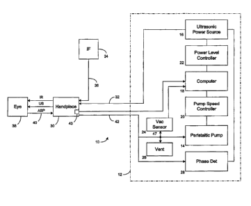
Device. FIG. 1 illustrates a phacoemulsification system
in block diagram
form, indicated generally by the reference numeral 10. The system has a
control unit 12,
indicated by the dashed lines in FIG. 1 which includes a variable speed
peristaltic pump
14, which provides a vacuum source, a source of pulsed ultrasonic power 16,
and a
microprocessor computer 18 that provides control outputs to pump speed
controller 20
and ultrasonic power level controller 22. A vacuum sensor 24 provides an input
to
computer 18 representing the vacuum level on the input side of peristaltic
pump 14.
Suitable venting is provided by vent 26.
A phase detector 28 provides an input to computer 18 representing a phase
shift
between a sine wave representation of the voltage applied to a
handpiece/needle 30 and
the resultant current into the handpiece 30. The block representation of the
handpiece 30
includes a needle and electrical means, typically a piezoelectric crystal, for
ultrasonically
vibrating the needle. The control unit 12 supplies power on line 32 to a
phacoemulsification handpiece/needle 30. An irrigation fluid source 34 is
fluidly coupled
to handpiece/needle 30 through line 36. The irrigation fluid and ultrasonic
power are
applied by handpiece/needle 30 to a patient's eye, or affected area or region,
indicated
diagrammatically by block 38. Alternatively, the irrigation source may be
routed to the
eye 38 through a separate pathway independent of the handpiece. The eye 38 is
aspirated
by the control unit peristaltic pump 14 through line/handpiece needle 40 and
line 42. A
switch 43 disposed on the handpiece 30 may be utilized as a means for enabling
a
surgeon/operator to select an amplitude of electrical pulses to the handpiece
via the
computer 18, power level controller 22 and ultrasonic power source 16 as
discussed
herein. Any suitable input means, such as, for example, a foot pedal (not
shown) may be
utilized in lieu of the switch 43.
FIG. 2 shows an alternative phacoemulsification system 50 incorporating all of
the elements of the system 10 shown in FIG. 1, with identical reference
characters
identifying components, as shown in FIG. 1. In addition to the irrigation
fluid source 34,
CA 02830583 2013-10-18
, =
13
a second irrigation fluid source 35 is provided with the sources 34,35 being
connected to
the line 36 entering the handpiece/needle 30 through lines 34a, 35a,
respectively, and to a
valve 59. The valve 59 functions to alternatively connect line 34A and source
34 and line
35A and source 35 with the handpiece/needle 30 in response to a signal from
the power
5 level controller 22 through a line 52.
As shown, irrigation fluid sources 34,35 are disposed at different heights
above
the handpiece/needle 30 providing a means for introducing irrigation fluid to
the
handpiece at a plurality of pressures, the head of the fluid in the container
35 being
greater than the head of fluid in the container 34. A harness 49, including
lines of
10 different lengths 44,46, when connected to the support 48, provides a
means for
disposing the containers 34,35 at different heights over the handpiece/needle
30.
The use of containers for irrigation fluids at the various heights is
representative
of the means for providing irrigation fluids at different pressures, and
alternatively,
separate pumps may be provided with, for example, separate circulation loops
(not
15 shown). Such containers and pumps can provide irrigation fluid at
discrete pressures to
the handpiece/needle 30 upon a command from the power controller 22.
Operation, The computer 18 responds to preset vacuum levels in input line 47
to peristaltic pump 14 by means of signals from the previously mentioned
vacuum sensor
24. Operation of the control unit in response to the occluded-unoccluded
condition of
20 handpiece 30 is shown in the flow diagram of FIG. 3. As shown in FIG.
3,11 the
handpiece aspiration line 40 becomes occluded, the vacuum level sensed by
vacuum
sensor 24 may increase. The computer 18 may provide operator-settable limits
for
aspiration rates, vacuum levels and ultrasonic power levels. As illustrated in
P10.3,
when the vacuum level sensed by vacuum sensor 24 reaches a predetermined level
as a
25 result of occlusion of the handpiece aspiration line 40, computer 18
provides signals to
pump speed controller 20 to change the speed of the peristaltic pump 14 which,
in turn,
changes the aspiration rate. Depending upon the characteristics of the
material occluding
handpiece/needle 30, the speed of the peristaltic pump 14 can either be
increased or
CA 02830583 2013-10-18
14
decreased. When the occluding material is broken up, the vacuum sensor 24
registers a
drop in vacuum level, causing computer 18 to change the speed of peristaltic
pump 14 to
an unoccluded operating speed.
In addition to changing the phacoemulsification parameter of aspiration rate
by
varying the speed of the peristaltic pump 14, the power level of the
ultrasonic power
source 16 can be varied as a function of the occluded or unoccluded condition
of
handpiece 30. FIG. 4 illustrates in flow diagram form a basic form of control
of the
ultrasonic power source power level using computer 18 and power level
controller 22.
The flow diagram of FIG. 4 corresponds to the flow diagram of FIG. 3 but
varies the
phacoemulsification parameter of the ultrasonic power level.
The impedance of the typical phacoemulsification handpiece varies with
frequency, or in other words, the handpiece is reactive. Dependence of typical
handpiece
phase and impedance as a function of frequency is shown in FIG. 8. In P10.8,
curve 64
represents the phase difference between current and voltage of the handpiece
as function
frequency and curve 66 shows the change in impedance of the handpiece as a
function of
frequency. The impedance exhibits a low at "Fr" and a high "Fa" for a typical
range of
frequencies, such as in the range of approximately 25 kHz to approximately 50
kHz.
Automatic tuning of the handpiece typically requires monitoring the handpiece
electrical signals and adjusting the frequency to maintain a consistency with
selected
parameters. To compensate for a load occurring at the tip of the
phacoemulsification
handpiece, the drive voltage to the handpiece can be increased while the load
is detected
and then decreased when the load is removed. This phase detector is typically
part of the
controller in this type of system. In such conventional phase detectors, the
typical output
is a voltage as proportional to the difference in alignment of the voltage and
the current
waveform, for example, -90 degrees as shown in FIG. 7. As shown in FIG. 8,
while
using the handpiece, the waveform varies in phase and correspondingly the
output
waveform also varies.
CA 02830583 2013-10-18
=
Heretofore, the standard technique for measuring electrical phase has been to
read
a voltage proportional to phase and also to frequency. This type of circuit
may be
calibrated for use with a single frequency. Changing the frequency may cause
the
calibration data to be incorrect As also seen in single frequency systems,
corrected
5 phase value will drift due to variation in the circuit parameters.
One other available approach utilizes a microprocessor to compare the value of
the phase detector output with that of a frequency detector and compute the
true phase.
This approach is fairly complex and is subject to drift of the individual
circuits as well as
resolution limitations. A block diagram 70 as shown in P10.9 is representative
of an
10 improved phase detector suitable for performing in accordance with the
design. Each of
the function blocks shown comprises conventional state-of-the-art circuitry of
typical
design and components for producing the function represented by each block as
hereinafter described.
The system converts voltage input 72 and current 74 from a phacoemulsification
15 handpiece 30 to an appropriate signal using an attenuator 76 on the
voltage signal to the
phacoemulsification handpiece, and a current sense resistor 78 and fixed gain
amplifier
for the handpiece 30 current. Thereafter, the system passes an AC voltage
signal 80 and
AC current signal 82 to comparators 84,86 which convert the analog
representations of
the phacoemulsification voltage and current to logic level clock signals.
The system feeds output from the comparator 84 into a D flip flop integrated
circuit 90 configured as a frequency divide by 2. The system then feeds output
92 of the
integrated circuit 90 into an operational amplifier configured as an
integrator 94. The
output 96 of the integrator 94 is a sawtooth waveform of which the final
amplitude is
inversely proportional to the handpiece frequency. A timing generator 98 uses
a clock
synchronous with the voltage signal to generate AID converter timing, as well
as timing
to reset the integrators at the end of each cycle. The system feeds this
signal into the
voltage reference of an A/D converter via line 96.
CA 02830583 2013-10-18
16
The voltage leading edge to current trailing edge detector 100 uses a D flip
flop
integrated circuit to isolate the leading edge of the handpiece voltage
signal. This signal
is used as the initiation signal to start the timing process between the
handpiece 30
voltage and handpiece 30 current. The output 102 of the leading edge to
current trailing
edge detector 1001$ a pulse proportional to the time difference in occurrence
of the
leading edge of the handpiece 30 voltage waveform and the falling edge of the
handpiece
current waveform.
The system uses another integrator circuit 104 for the handpiece phase signal
102
taken from the leading edge to current trailing edge detector 100. Output 106
of the
integrator circuit 104 is a sawtooth waveform in which the peak amplitude is
proportional
to the time difference in the onset of leading edge of the phacoemulsification
voltage and
the trailing edge of the onset of the handpiece current waveform. The system
feeds
output 106 of the integrator circuit 104 into the analog input or an A/D
(analog to digital
converter) integrated circuit 110. The positive reference input 96 to the A/D
converter
110 is a voltage that is inversely proportional to the frequency of operation.
The phase
voltage signal 96 is proportional to the phase difference between the leading
edge of the
voltage onset, and the trailing edge of the current onset, as well as
inversely proportional
to the frequency of operation. In this configuration, the two signals
frequency voltage
reference 96 and phase voltage 106 track each other over the range of
frequencies, so that
the output of the A/D converter 110 produces the phase independent of the
frequency of
operation.
In this arrangement, the system computer 18 (see FIGS. 1 and 2) is provided
with
a real time digital phase signal wherein 0 to 255 counts will consistently
represent 0 to
359 degrees of phase. No form of calibration is necessary since the
measurements are
consistent despite the frequencies utilized. For example, using AMPs operation
frequencies of 38 kHz and 47 kHz and integrator having a rise time of 150x 105
V/sec
and an 8 bit A/D converter having 256 counts, a constant ratio is maintained
and variation
in frequency does not affect the results. This shown in the following
examples.
CA 02830583 2013-10-18
17
LE 1
38 KHz Operation
Period of 1 clock cycle = 1/F @38 KHz = 26.32 times 104 S
Portion of one period for I = 90 deg = 26.32 times le s
Divided by 4 = 6.59 times 104 S
Integrator output for one reference cycle = (150 times 103 V/S) times (2632
times le s)
= 3.95 Volts
Integrator output from 90 degree cycle duration = (150 times 103 V/S) times
(6.59 times
10-6 S)
= 0.988 Volts
Resulting Numerical count from A/D converter = 3.95 Volts/256 counts = 0.0154
Volts
per count
Actual Number of A/D counts for 90 deg at 38 KHz = 0.988/0.0154 = 64 counts
EXAMPLE 2
47 KHz Operation
Period of 1 clock cycle=1/F @47KHz = 21.28 times 104 S
Portion of one period for I = 90 deg = 21.28 times 104 S
Divided by 4 = 5.32 times 104 S
Integrator output for one reference cycle = (150 times 103 V/S) times (21.28
times le s)
= 3.19 volts
Integrator output from 90 degree cycle duration = (150 times 103 V/S) times
(5.32 times
10-6S )
= 0.798 Volts
CA 02830583 2013-10-18
18
Resulting Numerical count from AID converter = 3.19 Volts/256 counts
= 0.0124 Volts per count
Actual Number of AID counts for 90 deg at 47 KHz = 0.798/0.0124 = 64 counts
This represents the baseline operation of the present system, namely the
ability to tune
the phacoemulsification handpiece to a generally acceptable level.
Energy Delivery. The following sections deal generally with the types
of
delivery of microburst energy generally employed to effectively carry out the
phacoemulsification procedure. With reference to FIG. 5, there is shown a flow
diagram
depicting basic control of the ultrasonic power source 16 to produce varying
pulse duty
cycles as a function of selected power levels. Each power pulse may have a
duration of
less than 20 milliseconds. As shown in FIG. 5, and by way of illustration
only, a 33%
pulse duty cycle is run until the power level exceeds a preset threshold; in
this case, 33%.
At that point, the pulse duty cycle is increased to 50% until the ultrasonic
power level
exceeds a 50% threshold, at which point the pulse duty cycle is increased to
66%. When
the ultrasonic power level exceeds 66% threshold, the power source is run
continuously,
i.e., a 100% duty cycle. Although the percentages of 33,50 and 66 have been
illustrated
in FIG. 5, it should be understood that other percentage levels can be
selected as well as
various duty cycles to define different duty cycle shift points. The pulse
duration in this
arrangement may be less than 20 milliseconds. This control along with the
tracking
mechanism herein described enables bursts of energy less than 20 milliseconds
in
duration.
With reference to FIG. 13, a rapid pulse duration of less than 20 milliseconds
is
provided with adequate energy to cut the tissue with kinetic or mechanical
energy. The
ultrasonic energy pulse may then be turned off long enough to significantly
decrease the
resultant heat level before the next pulse is activated. A surgeon/operator
may vary the
pulse amplitude in a linear manner via the switch 143 and the control unit 22
in response
to the selected pulse amplitude, irrigation and aspiration fluid flow rates,
controlling a
pulse duty cycle. As hereinabove noted, an off duty duration or cycle is
provided to
CA 02830583 2013-10-18
19
ensure heat dissipation before a subsequent pulse is activated. In this way,
increased
amplitude will increase tip acceleration and thus heat dissipation level for
tissue
damaging heat generation. That is, the surgeon/operator can use linear power
control to
select the correct acceleration necessary to cut through the tissue density
while the
control unit provides a corresponding variation in pulse width of less than 20
milliseconds and "off time" to prevent tissue de-compensation from heat. The
control
unit is programmed depending on the phacoemulsification handpiece chosen
(total
wattage) or the phacoemulsification tip (dimensions, weight). This use of
rapid pulsing is
similar to how lasers operate with very short duration pulses. Pulses in this
configuration
may have a repetition rate of between about 25 and 2000 pulses per second.
With reference to FIG. 5, if the handpiece aspiration line 38 is occluded, the
vacuum level sensed by the vacuum sensor 24 will increase. The computer 18 has
operator-settable limits for controlling which of the irrigation fluid
supplies 32,33 will be
connected to the handpiece 30. While two irrigation fluid sources, or
containers 32, 33
are shown, any number of containers may be utilized.
As shown in FIG. 6, when the vacuum level by the vacuum sensor 24 reaches a
predetermined level, as a result of occlusion of the aspiration handpiece line
38, the
computer controls the valve 38 causing the valve to control fluid
communication between
each of the containers 34,35 and the handpiece/needle 30.
Depending upon the characteristics of the material occluding the
handpiece/needle 30, as hereinabove described and the needs and techniques of
the
physician, the pressure of irrigation fluid provided the handpiece may be
increased or
= decreased. As occluded material is cleared, the vacuum sensor 24 may
register a drop in
the vacuum level causing the valve 38 to switch to a container 34,35,
providing pressure
at an unoccluded level.
More than one container may be utilized, such as three containers (not shown)
with the valve interconnecting to select irrigation fluid from any of the
three containers,
as hereinabove described in connection with the container system.
CA 02830583 2013-10-18
In addition to changing phacoemulsification handpiece/needle 30 parameter as a
function of vacuum, the occluded or unoccluded state of the handpiece can be
determined
based on a change in load sensed by a handpiece/needle by way of a change in
phase shift
or shape of the phase curve. A plot of phase angle as a function of frequency
is shown in
5 FIG. 10 for various handpiece 30 loading, a no load (max phase), light
load, medium load
and heavy load.
With reference to FIG. 11, representing max phase mode operation, the actual
phase is determined and compared to the max phase. If the actual phase is
equal to, or
greater than, the max phase, normal aspiration function is performed. If the
actual phase
10 is less than the max phase, the aspiration rate is changed, with the
change being
proportionate to the change in phase. FIG. 12 represents operation at less
than max load
in which load (see FIG. 10) detection is incorporated into the operation.
As represented in FIG. 11, representing max phase mode operation, if the
handpiece aspiration line 40 is occluded, the phase sensed by phase detector
sensor 28
15 will decrease (see FIG. 10). The computer 18 has operator-settable
limits for aspiration
rates, vacuum levels and ultrasonic power levels. As illustrated in FIG. 11,
when the
phase sensed by phase detector 28 reaches a predetermined level as a result of
occlusion
of the handpiece aspiration line 40, computer 18 instructs pump speed
controller 20 to
change the speed of the peristaltic pump 14 which, in turn, changes the
aspiration rate.
20 Depending upon the characteristics of the material occluding
handpiece/needle
30, the speed of the peristaltic pump 14 can either be increased or decreased.
When the
occluding material is broken up, the phase detector 28 registers an increase
in phase
angle, causing computer 18 to change the speed of peristaltic pump 14 to an
unoccluded
operating speed.
In addition to changing the phacoemulsification parameter of aspiration rate
by
varying the speed of the peristaltic pump 14, the power level and/or duty
cycle of the
ultrasonic power source 16 can be varied as a function of the occluded or
unoccluded
condition of handpiece 30 as hereinabove described.
CA 02830583 2013-10-18
21
Microburst enhanced operation. A representation of different pulse
characteristics
for previous operation is presented in FIG. 14. From FIG. 14, operation of
pulses may be
a constant application of power at a frequency of between about 25 kHz to
about 50 kHz
as illustrated in Plot A, or once every 80 milliseconds for a duration of 40
milliseconds
on and 40 milliseconds off as in Plot B, representing 12.5 pulses per second.
Alternately,
ultrasonic power delivery may occur once every 40 ms, for 20 ms on and 20 ms
off as in
Plot C. Plot D shows power applied every 20 ms for 10 ms and turned off for 10
ms.
Other non periodic arrangements may be employed, such as shown in Plot B, with
application of power for 10 ms periodically every 40 ms, with a resultant 30
ms off time.
These power application intervals represent solid, constant periods when
ultrasonic power is being applied to the handpiece and needle at a constant
power level
for a period of time. Again, while power may appear in the Figures to be
applied at a
continuous DC type of application, the Figures are intended to indicate actual
application
of power including a sinusoidal waveform being applied to the piezoelectric
crystals at a
frequency of generally between about 25 kHz and 50 kHz. The application of
power is
therefore not truly "constant." Application of power during this 150 ms period
is defined
as a constant application of a 25 kHz to 50 kHz sinusoid.
Cavitation, The present design offers enhancements over the waveforms of FIG.
14 by employing beneficial effects of cavitation and applying energy
accordingly.
Cavitation in the surgical environment may be defined as the violent collapse
of minute
bubbles in fluid, such as saline, water, or other applicable fluid. Cavitation
is the primary
means by which cells and nuclei can be broken or cut in ultrasonic surgical
systems,
including phacoemulsifiers. The system presented above can generate cavitation
by
providing a series of acoustic pressure waves forming an acoustic pressure
field
emanating from the tip of the phacoemulsifier handpiece 30. Acoustic pressure
waves
are the result of the phaco tip oscillating forward and back at the operating
frequency,
such as at the frequency of approximately 38 kHz.
CA 02830583 2013-10-18
=
22
Cavitation is the generation, oscillation, and collapse of minute bubbles in
the
operating fluid. In a phacoemulsification or other surgical scenario, bubbles
are created
by the acoustic waves emanating from the surgical ultrasonic tip, and may
therefore be
called acoustic cavitation. The violent collapse of these bubbles may create
most of the
forces that break up nuclei or produce the cutting or chopping characteristics
of tissue
fragmentation. Other bubble motion under the influence of the pressure field,
such as
resonant vibration discussed below, may also yield a desirable biological
effect.
In this ultrasonic environment, acoustic pressure is proportional to the
acoustic
source strength Qs or volume velocity of the tip, which is the effective tip
area A
(typically an annulus) multiplied by tip velocity. Tip velocity is the product
of the tip
vibration amplitude 8 and 27r multiplied by operating frequency. The tip is
relatively
small in comparison to the acoustic wavelength in fluid and acts as a point
radiator of
sound or monopole source at the operating frequency.
In this environment, low frequency sound tends to radiate in a spherical
manner,
with a pressure level that falls inversely with distance from the tip. The
pressure field at
a: distance r from a monopole source pulsating at a frequency co * (27d) is
given by:
p (iPocklKs)e
47r )
where Po and c are the density and sound speed of the medium, k is the wave
number, or
Gilc, and Q. is the source strength. Using Equation (1), pressure can be
expressed as:
p = iP0w2A15e-ikr (2)
47ix
From Equation (2), pressure is related to tip area, displacement, and the
square of the
operating frequency. Equation (2) provides a general guideline for determining
pressure
equivalence between tips of different sizes, frequencies, and displacements.
CA 02830583 2013-10-18
23
Acoustic source strength Q. may be calculated as follows. Assuming a solid
circular, flat end tip, operating at 24,500 Hz, with a radius of 1.44ram, and
a vibration
amplitude of 100 m (tip excursion 200 m):
= Area * velocity
or) * w * 8
=7r* (.00144)2* (2 * * 24,500) * (100 * 104)
Q. = 100 x 104 meters3/second (3)
Total acoustic power in this example, W, may be calculated as follows:
W = Po x c x k2 x (Q.)2 / 8ir (4)
where:
= / c
=(2*r*f)/c
= 2 * * 24,500 / 1500 --= 100 (5)
W = 1000 * 1500* 1002* (10 * 10-6)2 / 8r
¨= 6 Acoustic Watts
As the sound passes through fluid, such as water, saline, or other liquid, the
sound
encounters microscopic bubbles. A bubble exposed to the "tensile" or
"rarefactional" or
"negative" part of the wave has a tendency to expand. A bubble exposed to the
"compressional" or "positive" pillion of the wave tends to decrease in size or
shrink
slightly. Gas diffuses into the bubble when in the enlarged state due to force
differences.
Gas tends to dissipate, or diffuse out, when the bubble decreases in size.
Because the
surface area of the decreased bubble is less than the surface area of the
enlarged bubble,
less gas tends to diffuse out during this portion of the cycle than diffused
in during the
"enlarged" portion of the cycle. Over time the bubble tends to increase in
size, a
phenomenon known as rectified diffusion. If the pressure variation is not
significant, the
CA 02830583 2013-10-18
=
24
size difference between the enlarged and shrunken state is not significant
enough to
provide appreciable net gas inflow.
As bubbles increase in size due to rectified diffusion, these bubbles can
attain a
size wherein hydrodynamic forces on the bubble, such as gas pressure, surface
tension,
5 and so forth, reach dynamic equilibrium or resonance with the applied
sound field. In
situations of dynamic equilibrium, a bubble can oscillate vigorously, collapse
and break
apart. This oscillation and collapse of the bubble occurs when the pressure is
significant.
In the event the pressure is enough to produce rectified diffusion, small
bubbles will have
a tendency to continuously increase in size, oscillate, and then collapse.
Bubbles may
10 also divide without full collapse, resulting smaller bubbles that
increase in size and
continth the process. This phenomenon may be referred to as stable cavitation.
Stable cavitation produces a collection or cloud of bubbles that tend to
operate in
a relatively stable manner as long as the pressure field exists. In stable
cavitation, many
of the bubbles break apart without a full, violent collapse. Inducing stable
cavitation may
15 not be well suited to cell and nucleus cutting.
Transient cavitation may be defined as violent bubble collapse. When bubbles
violently collapse near a boundary, such as a cell wall, the bubbles expend a
significant
amount of pressure on the cell wall. The effect is similar to a water hammer
producing
very high pressures and temperatures concentrated within a small area. These
high
20 pressure/high temperature conditions can destroy tissue and denature the
proteins in the
cell. Transient cavitation results from quick expansion and violent collapse
of bubbles of
a very specific size relative to the acoustic driving frequency. This quick
expansion and
violent collapse results from the force of the driving waveform. Transient
cavitation is
sensitive to the driving waveform pressure level in that transient cavitation
may not occur
25 at all below some threshold level. Above the threshold, transient
cavitation will result as
long as bubbles of the correct size are available.
The absolute threshold for cavitation phenomena is generally frequency
dependent. In generating cavitation, the arrangement described herein
translates energy
CA 02830583 2013-10-18
from the driving, low frequency ultrasonic waveform into the mechanical
manipulation of
bubbles. The driving waveform emanating from the phaco tip may be termed a
pumping
wave. As more cavitation occurs, more energy is received from the pumping
wave. At
low pressure levels, such as below the threshold for cavitation, the low
frequency
5 pressure emitted from the tip is roughly proportional to tip excursion.
In this low
pressure scenario, little pressure is available to impact the cell wall or
nucleus. Some
mechanical impact may exist since the phaco tip vibrates and can thus cause
frictional
heating. An increase in driving excursion level tends to increase cavitation
activity.
Further drive amplitude increases result in radiated low frequency pressure no
longer
10 having the ability to track amplitude. This decorrelation between
pressure and amplitude
occurs as a result of energy transferring to cavitation. As the drive
amplitude is further
increased, the low frequency pressure field can decrease. Such a decrease in
the pressure
field is a result of bubbles obscuring the tip and acting as a cushion
shielding the pressure
field. This cushion can change the local acoustical properties of the fluid.
Thus the ratio
15 of pumping energy to cavitational energy changes as drive amplitude
increases.
FIG. 15 shows the resultant energy applied to a fluid for a system applying a
constant level of energy, i.e. continuous application of power for a period of
time, such as
2.0 seconds. The signal 1502 having multiple high amplitude spikes is one
having a low
power setting, while the signal 1501 exhibiting lower, choppier characteristic
has a higher
20 power setting. The low power signal 1502 exhibits relatively large
signal excursions,
indicative of transient cavitation. Between transient peaks, the signal level
for the low
power signal 1502 is at approximately the noise floor. The choppier and higher
power
signal 1501 exhibits a lower peak level, but a continuous signal above the
noise floor,
indicative of stable cavitation.
25 Removal of the noise floor and plotting of cavitation excursions for the
system of
FIG. 15 is presented in FIG. 16. The two waveforms, high power signal 1601 and
low
power signal 1602 display nearly identical overall cavitational energy over
the time
period shown. Thus while transient cavitation occurs less frequently,
transient cavitation
tends to release greater energy to the region or environment.
CA 02830583 2013-10-18
26
FIG. 17 shows the response of a system wherein power is applied in shorter
bursts, such as approximately .15 milliseconds on followed by approximately
.35
milliseconds off. The plot of FIG. 17 illustrates performance after noise
thresholding.
The first two bursts 1701 and 1702 begin with significant transient
cavitation, but this
transient cavitation tends to fall off relatively rapidly. FIG. 18 shows this
long pulsing,
.15 milliseconds on followed by .35 milliseconds off, as compared to
continuous
application of power. The long pulsing signal 1802 and the continuous signal
1801 have
similar total cavitational energy over the time period, but the pulsed
response 1802 uses '
less than approximately half the drive power. This lower drive power results
from the
system being energized for less than approximately half the time.
FIG. 19 illustrates application of continuous power 1901 in the environment
and a
shorter burst arrangement 1902. This shorter burst period 1902 employs a
series of bursts
such as repeatedly applying energy for 6 ms and resting for 24 ms for a total
period of 0.2
Seconds, then applying de minimis power, such as zero power, for 0.5 seconds.
FIG. 19
115 illustrates that nearly every burst of drive frequency energy in this
shorter burst period
1902 tends to generate transient cavitation. The time between bursts is
believed to enable
fluid to move sufficiently to replenish the area with bubbles of sufficient
size, or
dissolved gas, thus producing an environment again receptive to transient
cavitation.
In the present system, based on observation of performance in the presence of
short duration energy delivery, cavitation relates to energy delivery as shown
in FIG. 20.
FIG. 20 represents various energy applications in the phacoemulsification
environment
and the resultant cavitational energy. From FIG. 20, two to three milliseconds
are
typically required for the cavitational energy to rise to a maximum. Two to
three
milliseconds represents the time required for the phaco tip to achieve the
full requested
excursion and for the cavitation process, specifically transient cavitation,
to commence.
Once started, energy delivered tends to fall oft representing the transition
from transient
to stable cavitation. After six milliseconds, the handpiece becomes de-
energized, and
only residual "ringing" of the tip produces cavitation.
CA 02830583 2013-10-18
. .
. .
27
The dashed lines in P10.20 represent energy readings taken in the presence of
a
continuous application of energy, such as shown in FIGS. 15, 16, 18, and 19.
From FIG.
20, cavitation energy level is significantly lower in continuous mode.
Modulated Energy Delivery. The present design employs stable cavitation and
5 transient cavitation as follows. Power is applied in brief pulses, with
these brief pulses
having divided energy levels for the phaco environment presented above. In
particular, a
waveform such as that shown in FIG. 21 may be employed. Other similar
waveforms
may be employed and depend on the environment encountered, including but not
limited
to phaco conditions, tip size, operating frequency, fluid conditions, and
occlusion
10 conditions. FIG. 21 shows a modulated pulse delivering initial power by
an initial energy
period 2101 at 30 watts for a brief duration, such as 2 ms. The 30 watts
represents input
to the handpiece. The second period 2102 represents power delivered at 15
watts for a
period of 2 ms. The third period 2103 represents a time period, in this
example three
milliseconds, delivered at a specific level, such as 10 watts. The goal of the
modulated or
15 stepped power delivery arrangement is to initiate needle stroke above
the distance
necessary to generate transient cavitation as rapidly as possible. Once the
power
threshold required to induce transient cavitation has been achieved, power may
be
reduced for the remainder of the pulse.
= As may be appreciated by those skilled in the art, other timing and power
20 implementations may be employed. Examples of power schemes are provided
in FIGS.
22a-f, where power levels and timing are varied. The goal of varying the time
and power
is to attain transient cavitation as quickly as possible in the environment
presented
without generating significant heat. FIG. 22a shows a two step modulated pulse
at 30
watts for 2 ms and 15 watts for 4 ms. FIG. 22b is a 2.5 ms 35 watt pulse,
followed by a 1
25 ms 25 watt pulse, followed by a 1 ms 15 watt pulse, followed by a 1 ms 5
watt pulse.
FIG. 22c shows a 25 watt pulse for 2 ms, a 15 watt pulse for .5 ms, and a 10
watt pulse
for 2.5 ms. FIG. 22d is a 20 watt pulse for 3 ms and a 10 watt pulse for 3 ms.
FIG. 22e
shows a 40 watt pulse for 1.8 ms, a 25 ms pulse for 2 ms, and a 15 watt pulse
for 3 ms.
FIG. 22f is a 30 watt pulse for 3.5 ms, a 25 watt pulse for .5 ms, a 20 watt
pulse for .5 ms,
CA 02830583 2013-10-18
28
a 15 watt pulse for .5 ms, and a 10 watt pulse for 1 ms. As may be appreciated
by one of
ordinary skill in the art, other times and durations may be employed depending
on
circumstances.
While FIGs. 22a-f show essentially square waves going on and off at specific
times, it is not essential that the waves be square in nature. FIGs. 22g-i
illustrate an
alternative aspect of the invention wherein rounded waves, or graduated power
delivery
curves, are applied to the surgical area. As shown in FIGs. 22g-i, and as may
be
appreciated by those skilled in the art, sufficient power is delivered based
on the
circumstances presented to induce transient cavitation, typically by
delivering an initial
higher powered surge or burst of energy, followed by a dropoff in energy from
the initial
surge. The magnitude and time of the initial energy surge depends on
circumstances
presented, and may exhibit characteristics similar to or based in whole or in
part upon
curves similar to those shown in FIG. 20 for a typical phacoemulsification
surgical
environment.
The important factor in the present design is to provide transient cavitation
in the
environment in a relatively brief amount of time followed by a permissible
dropoff in
energy in an attempt to minimize energy delivered to the region. Thus a strong
or high
energy initial pulse followed shortly thereafter or immediately thereafter by
at least one
lower power pulse is the critical modulated power delivery method to achieve
the
foregoing desired performance.
In the environment discussed herein, application of ultrasonic energy may be
characterized as a strong or high energy short pulse being applied for a short
duration
followed by a dropoff in ultrasonic energy applied. Such waveforms include but
are not
limited to those waveforms shown in FIGs. 22a-22i. Cavitational energy, as
represented
in FIG. 20, is related to the application of power, but may in fact occur for
a different
time period than the ultrasound energy period. For example, but not by way of
limitation,
ultrasound energy may be applied for approximately three milliseconds,
reaching a peak
during these three milliseconds, while the resultant cavitational energy may
reach a peak
CA 02830583 2013-10-18
29
at a later time, such as at six milliseconds. Longer or shorter periods may be
employed
and/or observed, and the effectiveness of the differing time periods depends
on the
environment wherein the time periods are employed.
From the foregoing, depending on output conditions, transient or stable
cavitation
may be generated in different circumstances by the ultrasonic device. This
cavitation
may be employed in varying environments in addition to those disclosed herein,
including but not limited to a diagnostic environment and a chemical
processing
environment. The cavitation may also be employed in medical treatments or to
enhance
medical treatments. Enhancement of medical treatments may include, for
example,
assisting or accelerating the medical treatment. With respect to chemical
processing,
applying energy in the manner described can have a tendency to minimize heat
resulting
from ultrasound energy transmission, and can tend to minimize input energy
required to
effectuate a given chemical result.
Transient cavitation tends to require certain specific conditions to occur
effectively in the phaco environment, including but not limited to the
availability of
properly sized initial bubbles and/or dissolved gas in the fluid. When bubbles
of the
proper size and/or dissolved gas are not available, either because of low flow
or in the
presence of a high output level in a continuous power application mode,
transient
cavitation tends to transition to stable cavitation. Energy present in
transient cavitation
tends to be higher than that of stable cavitation. Pulsing energy as opposed
to constant
energy can provide certain advantages, such as enabling the fluid to resupply
properly
sized bubbles to facilitate transient cavitation, consuming and delivering
less total power
with less likelihood of causing thermal damage to tissue. Further, cavitation
in the
presence of a pulsed energy delivery mode, for the phaco system described
herein,
requires approximately two or three milliseconds to attain a maximum value.
Cavitation
begins to then decrease as transient cavitation transitions to stable
cavitation.
The pulsing of energy described herein may be performed in software, hardware,
firmware, or any combination thereof, or using any device or apparatus known
to those
CA 02830583 2013-10-18
skilled in the art when programmed according to the present discussion. A
sample block
diagram of the operation of the invention as may be implemented in software is
presented
in FIG. 23, which is an extension of the implementation of FIG. 13. From FIG.
23, after
evaluating whether pulse mode has been enabled, the system evaluates whether
enhanced
5 pulse mode has been enabled. If not, the system proceeds according to
FIG. 13.
If enhanced pulse mode has been enabled, the Settings Required are received.
Settings Required may include, but are not limited to, overall cycle time, a
desired
procedure or function to be performed (sculpting, chopping, etc.), desire to
provide bursts
or long continuous periods of power application, desired transient cavitation
energy
10 application amplitude, desired transient cavitation energy application
period, desired
lower amplitude energy level, desired lower amplitude energy duration, pause
between
transient application energy bursts, and/or other pertinent information.
Certain lookup
tables may be provided in determining Settings Required, including but not
limited to
tables associating popular settings with the specific performance parameters
for the
15 desired setting. For example, if the desired function is "chop," the
system may translate
the desired "chop" function selection into a standardized or predetermined set
of
performance parameters, such as a 150 millisecond "burst on" period, followed
by an 350
ms "long off period," where the "burst on" period comprises 1 millisecond
transient
cavitation high energy periods followed by a 3 millisecond lower energy
period, followed
20 by a 1 millisecond pause, repeated sufficiently to fill the 150
millisecond "burst on"
period. The system takes the Settings Required and translates them into an
Operation
Set, or operation timing set, the Operation Set indicating the desired
operation of the
phacoemulsification handpie,ce tip when performing ultrasonic energy or power
delivery.
Input 2302 represents an optional input device, such as a foot pedal,
electronic or
25 software switch, switch available on the phacoemulsification handpiece,
or other input
device known to those skilled in the art, that allows the surgeon/operator to
engage and
enable ultrasonic power to be applied according to the Operation Set. For
example, a
foot pedal may be supplied that issues an on/off command, such that when
depressed
power is to be applied according to the operation set, while when not
depressed power is
CA 02830583 2013-10-18
31
not supplied to the phacoemulsification handpiece tip. Different input devices
may
enable different modes of operation. For example, a multiple position switch
may be
provided that allows for application of ultrasonic power according to one
Operation Set,
while moving the switch to another position allows for application of
ultrasonic power
according to a different Operation Set. Alternately, one position of the
switch may allow
for power application at one level according to one Operation Set, while
another position
of the switch may enable a higher ultrasonic power level at the same or a
different
operational timing set. Operation Set as used herein refers to the timing of
pulses and/or
energy applications and on/off periods for the application of power as
described herein.
Switching may also be nonlinear, such as one detent or setting for the switch
providing
only irrigation to the handpiece 30, a second detent or setting providing a
pump on plus
irrigation, and a third detent or setting providing irrigation and aspiration
wherein
ultrasound is introduced and may be increased by applying further engagement
of the
switch or foot pedal. In this instance, a foot pedal depressed to the third
position or
detent will enable the operator or surgeon to apply energy according to a base
operational
timing set and amplitude, such as a first operational timing set with a first
transient
cavitation inducing amplitude, while further depression of the foot pedal
would allow
application of a second operational timing set and/or a second amplitude. If
increased
amplitude is desired, depressing the foot pedal past the third detent may
linearly change
the amplitude from a value of 0% of available ultrasonic power or tip stroke
length to a
value of 100% of ultrasonic power or tip stroke length, or some other value
between 0%
and 100%. In the present design, amplitudes during energy application periods
typically
range from about 0 watts to 35 watts at 100% power (input to the handpiece
30).
As may be appreciated, virtually any Operation Set and operation timing set
may
be employed while within the course and scope of this invention. In
particular, the
system enables operation in multiple configurations or operational timing
sets, each
typically accessible to the user via the computer. For example, the user may
perform a
chop operation using one operational timing set, a sculpt operation using
another
operational timing set, and when encountering particular special conditions
employing
CA 02830583 2013-10-18
32
yet another operational timing set These configurations may operate
dynamically, or "on
the fly."
The system typically has a frame rate, which may be any period of time less
than
the smallest allowable power on or power off period for the device. A counter
counts the
number of pulses, and if the Operation Set dictates that ultrasonic power is
to be
delivered at a certain frame number, an indication in the form of an
electronic signal is
delivered to the handpiece tip at that frame time. Other implementations
beyond that
shown in FIG. 23 may be employed while still within the scope of the present
invention.
FIG. 24A illustrates the automatic or user controlled altering of the
amplitude,
with three different amplitude levels having the same timing. Alternate timing
may be
made available in addition to the different amplitudes. Additionally, the
system may
operate to address receipt or encounter of an occlusion as sensed by a sensor,
typically
located in the system. As in FIGs. 3 and 4, the handpiece or system may employ
a sensor
to sense a change in flow or vacuum, i.e. pressure, conditions. A change in
flow or
vacuum/pressure conditions sensed by the sensor indicates the presence of an
occlusion,
and upon sensing the presence of an occlusion, the handpiece or system may
feed back an
occlusion indication to the computer 18. An occlusion indication may cause the
computer 18 to automatically alter the Operation Set to an occlusion related
Operation
Set such as that illustrated in FIG. 24B.
It will be appreciated to those of skill in the art that the present design
may be
applied to other systems that perform tissue extraction, such as other
surgical procedures
used to remove hard nodules, and is not restricted to ocular or
phacoemulsification
procedures. In particular, it will be appreciated that any type of hard tissue
removal,
sculpting, or reshaping may be addressed by the application of ultrasonic
power in the
enhanced manner described herein.
Although there has been hereinabove described a method and apparatus for
controlling the ultrasonic power transmitted from a phacoemulsification
handpiece
utilizing, inter cilia, the voltage current phase relationship of the
piezoelectric
=
CA 02830583 2013-10-18
33
phacoemulsification handpiece and delivering ultrasonic power using relatively
short
pulses comprising multiple brief power bursts sufficient to induce transient
cavitation in
the environment presented, for the purpose of illustrating the manner in which
the
invention may be used to advantage, it should be appreciated that the
invention is not
limited thereto. Accordingly, any and all modifications, variations, or
equivalent
arrangements which may occur to those skilled in the art, should be considered
to be
within the scope of the present invention as defined in the appended claims