Note: Descriptions are shown in the official language in which they were submitted.
SCANNING REAL-TIME MICROFLUIDIC THERMOCYCLER AND METHODS FOR
SYNCHRONIZED THERMOCYCLING AND SCANNING OPTICAL DETECTION
TECHNICAL FIELD
[0002] The systems and methods disclosed herein relate generally to
the automated
execution of nucleic acid amplification assays, such as Polymerase Chain
Reaction (PCR), and in
some instances real-time PCR, in a plurality of micro-fluidic reaction
chambers in a microfluidic
cartridge. The system may subsequently detect target nucleic acids, e.g.,
target amplicons, within
each of the reaction chambers.
BACKGROUND OF THE INVENTION
[0003] The medical diagnostics industry is a critical element of
today's healthcare
infrastructure. At present, however, in vitro diagnostic analyses, no matter
how routine, have
become a bottleneck in patient care. There are several reasons for this.
First, many diagnostic
analyses can only be done with highly specialized equipment that is both
expensive and only
operable by trained clinicians. Such equipment may be found in only a few
locations¨ often just
one in any given urban area. This requires hospitals to send out samples for
analyses to these
locations, thereby incurring shipping costs and transportation delays, and
possibly even sample
loss or mishandling. Second, the equipment in question is typically not
available "on-demand" but
instead runs in batches, thereby delaying the processing time for many samples
as they must wait
for a machine to reach capacity before they can be run.
[0004] Understanding that diagnostic assays on biological samples may
break
down into several key steps, it is often desirable to automate one or more
steps. For example, a
biological sample, such as those obtained from a patient, can be used in
nucleic acid amplification
assays, in order to amplify a target nucleic acid (e.g., DNA, RNA, or the
like) of
1
CA 2833262 2018-07-05
CA 02833262 2013-10-15
WO 2012/142516 PCT/US2012/033667
interest. Once amplified, the presence of a target nucleic acid, or
amplification product of a
target nucleic acid (e.g., a target amplicon) reactor can be detected, wherein
the presence of a
target nucleic acid and/or target amplicon is used to identify and/or quantify
the presence of a
target (e.g., a target microorganism or the like). Often, nucleic acid
amplification assays involve
multiple steps, which can include nucleic acid extraction, nucleic acid
amplification, and
detection. It is desirable to automate certain steps of these processes.
[0005] There is a need for a method and apparatus for carrying out
molecular
diagnostic assays on multiple samples in parallel, with or without
amplification of target nucleic
acids, and detection on a prepared biological samples. The system may be
configured for high
throughput, and operation in a commercial reference laboratory or at the point
of care, thereby
eliminating the need to send the sample out to a specialized facility.
SUMMARY OF THE INVENTION
[0006] The embodiments disclosed herein relate to methods and devices
for the
simultaneous testing of multiple samples. Certain embodiments contemplate an
apparatus for
performing real-time nucleic acid amplification and detection. The apparatus
can include a
detector head comprising a plurality of photodetector and light source pairs.
The detector head
can be mounted on a rail, wherein the detector and light source pairs are
aligned in a first row
and a second row. The apparatus can include a receptacle for a microfluidic
cartridge that has a
plurality of independent rpction chambers aligned in adjacent columns of a
first row and a
second row. The apparatus can also include an aperture plate that is
configured to be positioned
over the microfluidic cartridge when the cartridge is present in the
receptacle. The aperture plate
can include a plurality of apertures that are each aligned over each of the
plurality of reaction
chambers when the receptacle is holding the microfluidic cartridge. The
detector head can be
located over the aperture plate, and be moveable along the rail, such that
each of the plurality of
photodetector and light source pairs in the first row can be positioned over
each aperture in the
first row of the aperture plate, and each of the plurality of photodetector
and light source pairs in
the second row can be positioned over each aperture in the second row of the
aperture plate.
[0007] In some embodiments, the apparatus also includes a second
detector head that
has a plurality of photodetector and light source pairs aligned into a first
row and a second row.
The second detector head can be mounted on the rail. The apparatus can also
include a second
receptacle for a microfluidic cartridge including a plurality of independent
reaction chambers
aligned in adjacent columns of a first 'row and a second row. The apparatus
can also include a
second aperture plate configured to be positioned over the second microfluidic
cartridge when
the second cartridge is present in the second receptacle, and which can
include a plurality of
-2-
CA 02833262 2013-10-15
WO 2012/142516 PCMJS2012/033667
apertures that are each aligned over each of the plurality of reaction
chambers of the second
microfluidic cartridge when the second receptacle is holding the second
microfluidic cartridge.
The second detector head can be located over the aperture plate, and can be
moveable along the
rail such that each of the plurality of photodetector and light source pairs
in the first row of the
second detector head can be positioned over each aperture in the first row of
the second aperture
plate, and each of the plurality of photodetector and light source pairs in
the second row of the
second detector head can be positioned over each aperture in the second row of
the second
aperture plate.
[0008] In some embodiments, the photodetector and light source pairs
can include at
least six different photodetector and light source pairs operating in six
different wavelengths. In
some embodiments, the six different wavelengths comprise a light source
emitting a green
colored light, a light source emitting a yellow colored light, a light source
emitting an orange
colored light, a light source emitting a red colored light, and a light source
emitting a crimson
colored light. In some embodiments, the detector head includes at least N rows
of photodetector
and light source pairs, and the detector is configured to move to at least M +
N -1 positions over
an aperture plate comprising M rows of apertures.
[0009] In some embodiments, the aperture plate comprises steel,
aluminum, nickel,
or a combination thereof. In some embodiments, the aperture plate can have a
thickness of
approximately .25 inches. In some embodiments, at least part of the aperture
plate is
electrochemically oxidized to be darker than when the aperture plate is not
electrochemically
oxidized. In some embodiments, the aperture plate provides substantially
uniform pressure
across the area of the microfluidic cartridge, when the cartridge is present
within the receptacle.
In some embodiments, the aperture plate comprises at least one of aluminum,
zinc or nickel, the
=
aperture plate further comprising a colorant.
100101 In some embodiments, the apparatus further comprises a heater
plate, wherein
the heater plate is positioned underneath the microfluidic cartridge when a
cartridge is present in
the receptacle. In some embodiments the heater plate comprises at least one of
glass or quartz.
In some embodiments, the aperture plate provides substantially uniform
pressure across the area
of the microfluidic cartridge when a cartridge is present within the
receptacle. The substantially
uniform pressure can facilitate substantially uniform thermal contact between
the microfluidic
reaction chambers and the heater plate. As such, in some embodiments, the
aperture plate
provide uniform pressure that can ensure that each of the plurality of
reaction chambers or
reactors in the microfluidic cartridge are in uniformly thermal contact or
communication with a
respective a plurality of heating elements located within the heater plate.
-3-
CA 02833262 2013-10-15
WO 2012/142516 PCMJS2012/033667
NOM In some embodiments, the apparatus further comprises a
photodetector, the
photodetector located over the aperture plate, wherein the micro-fluidic
chamber is configured to
receive light at a glancing angle from a light source relative to the
photodetector. In some
embodiments, the heater plate comprises a plurality of heating elements,
wherein each of the
plurality of heating elements is positioned such that when the microfluidic
cartridge is present in
the receptacle, the plurality of heating elements are in thermal connection
with each of the
plurality of reaction chambers, respectively.
[0012] Certain embodiments contemplate a method implemented on one or
more
computer processors for optimizing protocols, such as polymerase chain
reaction (PCR)
protocols or the like, for simultaneously performing a plurality of thermal
cycling reactions,
wherein each thermal cycling reaction comprises one or more detection steps,
and wherein the
thermal cycling reactions are performed in a plurality of reactors. The method
can include the
steps of determining or providing or accessing a detection cycle time for each
of the plurality of
reactors; receiving or accessing a protocol step, the step associated with a
step duration, the step
comprising a time for detection; and determining a first adjustment to the
step such that the step
duration is a multiple of the detection cycle time.
[0013] In some embodiments the method further comprises determining a
second
adjustment to the step, wherein the time for detection is a multiple of the
detection cycle time
when the step is adjusted by the first adjustment and by the second
adjustment. In some
embodiments the method further comprises determining a starting offset
adjustment based on a
position of a reaction chamber associated with the protocol. In some
embodiments, the
detection cycle time comprises the amount of time required for a detector head
to perform a
predetermined plurality of detections for a reactor. In some embodiments, the
detection cycle
time includes a time required for movement of the detector head to each of a
plurality of reactors
and movement of the detector head to the start position. In some embodiments,
the method
further comprises initiating the protocol.
[0014] Certain embodiments contemplate a non-transitory computer-
readable
medium comprising instructions, the instructions configured to cause one or
more processors to
perform the following steps: determining or providing or accessing a detection
cycle time;
receiving or accessing a protocol step, wherein the step is associated with a
step duration, and
the wherein step includes a time for detection; and determining a first
adjustment to the step
such that the step duration is a multiple of the detection cycle time.
[0015] In some embodiments, the protocol step is associated with a
protocol from a
plurality of protocols. Each of the plurality of protocols can be associated
with at least one of a
plurality of thermal cycling reactions, such as polymerase chain reaction
(PCR) protocols,
-4-
CA 02833262 2013-10-15
WO 2012/142516 PCT/US2012/033667
wherein each thermal cycling reaction comprises one or more detection steps,
and wherein the
determining a first adjustment is based at least in part on a timing of one or
more detection steps
associated with the thermal cycling reactions of at least two or more of the
plurality of protocols
when the two or more of the plurality of protocols are simultaneously run. In
some
embodiments, the method also includes the step of determining a second
adjustment to the step,
wherein the time for detection is a multiple of the detection cycle time when
the step is adjusted
by the first adjustment and by the second adjustment. In some embodiments, the
method also
includes the step of determining a starting offset adjustment based on a
position of a reaction
chamber associated with the protocol. In some embodiments, the detection cycle
time includes
the amount of time required for a detector head to perform a predetermined
plurality of
detections for a reaction chamber. In some embodiments, the detection cycle
time also includes
a time required for movement of the detector head to each of a plurality of
reaction chamber
detection positions and movement of the detector head to a start position. In
some
embodiments, the method further comprises initiating the protocol.
[0016] Certain embodiments contemplate a system for optimizing
protocols for a
plurality of reaction chambers. The system can include a processor configured
to perform the
following: determining or providing or accessing a detection cycle time;
receiving or accessing a
protocol step, wherein the step can be associated with a step duration, and
wherein the step
includes a time for detection; and determining a first adjustment to the step
such that the step
duration is a multiple of the detection cycle time.
[0017] In some embodiments, the protocol step is associated with a
protocol from a
plurality of protocols. Each of the plurality of protocols can be associated
with at least one of a
plurality of thermal cycling reactions, such as a polymerase chain reaction
(PCR) protocol,
wherein each thermal cycling reaction comprises one or more detection steps,
and wherein the
determining a first adjustment is based at least in part on a timing of one or
more detection steps
associated with the thermal cycling reactions of at least two or more of the
plurality of protocols
when the two or more of the plurality of protocols are simultaneously run. In
some
embodiments, the processor is also configured to determine a second adjustment
to the step,
wherein the time for detection is a multiple of the detection cycle time when
the step is adjusted
by the first adjustment and by the second adjustment. In some embodiments, the
processor is
also configured to determine a starting offset adjustment based on a position
of a reaction
chamber associated with the protocol. In some embodiments, the detection cycle
time includes
the amount of time required for a detector head to perform a predetermined
plurality of
detections for a reaction chamber. In some embodiments, the detection cycle
time also includes
a time required for movement of the detector head to each of a plurality of
reaction chamber
-5-
detection positions and movement of the detector head to the start position.
In some
embodiments, the processor is further configured to initiate the protocol.
[0018] Certain embodiments contemplate a method for simultaneously
performing real-time PCR in a plurality of PCR reaction chambers, comprising:
(a) providing
a scan time sufficient for a detector assembly to perform a scan cycle during
which it can scan
each of the plurality of PCR reaction chambers for at least one detectable
signal and become
ready to repeat the scan; (b) providing a reaction protocol for each of the
PCR reaction
chambers that includes multiple cycles, each cycle comprising a cycle time
that includes at
least one heating step, at least one cooling step, and at least one
temperature plateau that
includes a reading cycle period during which the detector assembly is to scan
the reaction
chamber for at least one detectable signal; (c) determining, using a
processor, whether the cycle
time for that reaction chamber is the same as or an integer multiple of the
scan time, and if not,
adjusting the scan time or the cycle time so that the cycle time is the same
as or an integer
multiple of the scan time; (d) performing at least steps (b) and (c) for the
reaction protocol for
each of the plurality of PCR reaction chambers so that the cycle time for each
reaction protocol
is the same as or an integer multiple of the scan time; and (e) under
direction of a processor,
performing real time PCR on each of the reaction chambers using the reaction
protocol for each
of the reaction chambers, including performing multiple scan cycles with the
detector
assembly, wherein each PCR reaction chamber is scanned by the detector
assembly during each
reading cycle period for that reaction chamber.
[0019] In some embodiments the method further comprises phase
adjusting the
cycle time of the reaction protocol for at least one of the reaction chambers.
In some
embodiments, at least one said reaction protocol is different from another
said reaction
protocol. In some embodiments, at least one cycle time in one reaction
protocol is different
from the cycle time in another reaction protocol.
[0019a] According to an aspect of the invention is a method
implemented on one
or more computer processors for optimizing protocols for simultaneously
performing a
plurality of thermal cycling reactions, wherein each thermal cycling reaction
comprises one or
more detection steps, and wherein the thermal cycling reactions are performed
in a plurality of
reactors, using a plurality of heating elements in thermal communication with
the plurality of
reactors and a detector head, the method comprising:
determining or providing or accessing a detection cycle time for each of the
plurality of
reactors;
6
CA 2833262 2019-06-10
receiving or accessing a protocol step of a protocol, the step associated with
a step
duration, the step comprising a time for detection;
determining a first adjustment to the step such that the step duration is a
multiple of the
detection cycle time; and
controlling the detector head and at least one of the plurality of heating
elements to
perform the protocol modified to include the first adjustment to the step.
[0019b] According to another aspect of the invention is non-
transitory computer-
readable medium comprising instructions, the instructions configured to cause
one or more
processors to perform a method for optimizing protocols for performing a
plurality of thermal
cycling reactions, each thermal cycling reaction comprising one or more
detection steps, the
thermal cycling reactions performed in a plurality of reactors, the method
comprising:
determining or providing or accessing a detection cycle time for each of the
plurality of
reactors;
receiving or accessing a protocol step of a protocol, the step associated with
a step
duration, the step comprising a time for detection;
determining a first adjustment to the step such that the step duration is a
multiple of the
detection cycle time; and
controlling a detector head to perform the protocol modified to include the
first
adjustment to the step.
[0019c] According to another aspect of the invention is system for
optimizing
protocols for performing a plurality of thermal cycling reactions, each
thermal cycling reaction
comprising one or more detection steps, the thermal cycling reactions
performed in a plurality
of reaction chambers using a plurality of heating elements in thermal
communication with the
plurality of reaction chambers, the system comprising:
a processor configured to:
determining or providing or accessing a detection cycle time for each of the
plurality of reaction chambers:
receiving or accessing a protocol step of a protocol, the step associated with
a
step duration, the step comprising a time for detection;
determining a first adjustment to the step such that the step duration is a
multiple
of the detection cycle time; and
controlling a detector head and at least one of the plurality of heating
elements
to perform the protocol modified to include the first adjustment to the step.
6a
CA 2833262 2019-06-10
[0019d] According
to another aspect of the invention is a method for
simultaneously performing reactions in a plurality of reaction chambers,
comprising:
(a) providing a scan time sufficient for a detector assembly to perform a scan
cycle
during which it can scan each of the plurality of reaction chambers for at
least one detectable
signal and become ready to repeat the scan;
(b) providing a reaction protocol for each of the reaction chambers that
includes
multiple cycles, each cycle comprising a cycle time that includes at least one
heating step, at
least one cooling step, and at least one temperature plateau that includes a
reading cycle period
during which the detector assembly is to scan the reaction chamber for at
least one detectable
signal;
(c) determining, using a processor, whether the cycle time for that reaction
chamber is
the same as or an integer multiple of the scan time, and if not, adjusting the
scan time or the
cycle time so that the cycle time is the same as or an integer multiple of the
scan time;
(d) performing at least steps (b) and (c) for the reaction protocol for each
of the plurality
of reaction chambers so that the cycle time for each reaction protocol is the
same as or an
integer multiple of the scan time; and
(e) under direction of a processor, performing reactions in each of the
reaction chambers
using the reaction protocol for each of the reaction chambers, including
performing multiple
scan cycles with the detector assembly, wherein each reaction chamber is
scanned by the
detector assembly during each reading cycle period for that reaction chamber.
[0019e] According
to another aspect of the invention is method for
simultaneously performing
polynucleotide amplification according to a plurality of
amplification protocols on a system comprising a plurality of reaction
chambers, a plurality of
heating elements in thermal communication with the plurality of reaction
chambers, a detector
head comprising a plurality of photodetector and light source pairs, wherein
the detector head
is movable such that the detector head can perform a detection with each of
the plurality of
photodetector and light source pairs at each of the plurality of reaction
chambers, the method
comprising:
(a) determining a detection cycle time, the detection cycle time comprising
the amount
of time required to perform a detection with the detector head on each of the
plurality of
reaction chambers with each of the plurality of photodetector and light source
pairs;
(b) configuring the detector head and at least one of the plurality of heating
elements
based on an amplification protocol of the plurality of amplification
protocols, the amplification
6b
CA 2833262 2019-06-10
protocol comprising one or more step cycles, each step cycle having a step
cycle time, wherein
each step cycle includes:
(i) activating the at least one of the plurality of heating elements to reach
a
temperature plateau,
(ii) maintaining the temperature plateau via the at least one of the plurality
of
heating elements for a first portion of the step cycle time,
(iii) deactivating the at least one of the plurality of heating elements for a
second
portion of the step cycle time, and
(iv) activating the detector head at a detection cycle time during the step
cycle
time;
(c) determining the first portion of the step cycle time is not an integer
multiple of the
detection cycle time;
(d) modifying the amplification protocol to extend a duration of the first
portion of the
step cycle time during which the at least one of the plurality of heating
elements maintains the
temperature plateau such that the step cycle time becomes an integer multiple
of the detection
cycle time; and
(e) controlling the detector head and at least one of the plurality of heating
elements
based at least in part on the modified amplification protocol,
[00191] According
to another aspect of the invention is an apparatus for
performing real-time nucleic acid amplification and detection, comprising:
an optical module comprising:
an enclosed housing comprising a bottom side;
a detector head mounted on a rail housed in the optical module, the detector
head
comprised of a plurality of detector pairs, each detector pair having at least
one light source(s)
and at least one light detector;
an aperture plate fixed to the bottom side of the optical module, the aperture
plate
comprising a plurality of apertures;
a normalizer plate fixed to the bottom side of the optical module to calibrate
the detector
pairs in the detector head, the normalizer plate comprised of a plurality of
calibration
components; and
a receiving tray attached to the optical module for receiving a microfluidic
cartridge
below the aperture plate, the microfluidic cartridge comprising a plurality of
independent
reaction chambers, wherein the receiving tray positions the microfluidic
cartridge below the
6c
CA 2833262 2019-06-10
optical module, such that each of the plurality of reaction chambers is
aligned with an aperture
of the aperture plate.
BRIEF DESCRIPTION OF THE DRAWINGS
[0020] Figure IA is a front plan view of a diagnostic apparatus as
used in certain
of the embodiments.
[0021] Figure I B is a top perspective view of the diagnostic
apparatus of Figure
IA showing certain of the apparatus' internal components.
[0022] Figure 2 illustrates an interior view of the diagnostic
apparatus of
Figures IA and I B.
[0023] Figure 3A illustrates a top-plan view of one possible
microfluidic
arrangement within certain embodiments of a microfluidic cartridge as
described herein.
6d
CA 2833262 2019-06-10
CA 02833262 2013-10-15
WO 2012/142516 PCMJS2012/033667
100241 Figure 3B illustrates the layout of a heater substrate in
relation to the reaction
chamber of certain of the embodiments.
[0025] Figure 4A illustrates an exterior view of the optical module
including the
detector head of certain of the embodiments described herein.
[0026] Figure 4B illustrates a view of the optical module of Figure 4A
with a side
cover removed.
[0027] Figure 4C illustrates a bottom view of the optical module of
Figure 4A.
[0028] Figure 5 illustrates a detector head used within the optical
module of certain
of the embodiments along the line 13 of Figure 4B.
[0029] Figure 6 depicts the layout of the light sources and optical
detectors as used in
certain of the embodiments of the detector head disclosed herein.
[0030] Figure 7 is a graph of the fluorescence versus time of using real
time PCR of
target nucleic acids performed in an apparatus of certain embodiments as
described herein.
[0031] Figure 8 is an abstract depiction of certain of the chamber,
aperture, and
heating layers found in certain of the embodiments as described herein.
[0032] Figures 9A-H illustrate various perspectives of one embodiment of
the
aperture plate.
[0033] Figure 10 illustrates various dimensions of the perspectives of
the aperture
plate of Figures 9A-H.
[0034] Figure 11 is plot of a portion of a thermal profile for a
possible protocol
implemented in certain of the embodiments.
[0035] Figure 12 is a flow diagram depicting a process for determining
protocol
durations, offsets, and detection times, so as to optimize and regiment
detector efficiency.
[0036] Figure 13 illustrates a portion of a user interface for selecting
durations of
certain protocol steps and substeps and determination of the accompanying
intra-cycle
adjustment.
[0037] Figure 14 is a plot of a thermal profile comprising an inter-
cycle adjustment.
[0038] Figures 15A-C plot a plurality of thermal profiles for a
plurality of protocols
implemented in certain of the embodiments. Figures 15A and 15B illustrate the
character of the
protocol profiles prior to the starting offset adjustment. Figure 15C
illustrates the plurality of
protocol profiles relative to one another after applying the starting offset
adjustments.
[0039] Figure 16 is plot of a thermal profile under active cooling as
implemented in
certain of the embodiments.
-7-
CA 02833262 2013-10-15
WO 2012/142516 PCT/US2012/033667
DETAILED DESCRIPTION
[0040] Certain of the present embodiments contemplate an apparatus,
referred to
herein as a thermocycler, which may consistently heat and analyze microfluidic
chambers.
Polynucleotide amplification, such as by real-time PCR, can be performed
within the
microfluidic chambers. In some embodiments, the thermocycler can be configured
to perform .
individual thermocycling and detection protocols in a plurality of
microfluidic reaction
chambers within a microfluidic cartridge. The thermocycling can be used to
amplify nucleic
acids, e.g., DNA, RNA or the like, e.g., by real-time PCR or other nucleic
acid amplification
protocols described herein, within the microfluidic reaction chambers. The
thermocycler may
comprise a detector head, comprising a plurality of detector pairs, e.g., six
or more detector head
pairs, wherein each detector pair comprises a light-emitting source, e.g., an
LED or the like, and
a cognate photodiode. In some embodiments, each individual detector pair is
configured to
generate and detect light emitted from a fluorescent moiety, e.g., a
fluorescent probe, to indicate
the presence of a target polynucleotide.
[0041] As used herein, the term "microfluidic" refers to volumes of
less than 1 ml,
preferably less than 0.9 ml, e.g., 0.8 ml, 0.7 ml, 0.6 ml, 0.5 ml, 0.4 ml, 0.3
ml, 0.2 ml, 0.1 ml, 90
I, 80 I, 70 I, 60 1, 50 I, 40 11, 30 1, 20 1, 10 I, 5 11, 4 111,3 I,
2 I, 1 1, or less, or any
amount in between. It is to be understood that, unless specifically made clear
to the contrary,
where the term PCR is used herein, any variant of PCR including but not
limited to real-time
and quantitative PCR, and any other form of polynucleotide amplification is
intended to be
encompassed.
[0042] The detection process used in the assay may also be multiplexed
to permit
multiple concurrent measurements on multiple reactions concurrently. In, some
embodiments,
these measurements may be taken from separate reaction chambers. Certain of
these
embodiments perform a plurality of PCR reactions simultaneously in a single
PCR reaction
chamber, e.g., multiplex PCR. A PCR protocol may comprise guidelines for
performing the
successive annealing and denaturing of the polynucleotides in the reaction
chamber prior to
detection. Such guidelines, comprising a time profile for heating the chamber,
may be referred
to as a "protocol". Certain of the disclosed embodiments facilitate consistent
heating and/or
cooling across a plurality of reaction chambers performing PCR, while
facilitating detection
using a sensor array. In certain embodiments, the apparatus may comprise an
aperture plate
which facilitates consistent heating and cooling of the reaction chambers by
applying pressure to
a cartridge containing a plurality of PCR reaction chambers. Certain details
and methods for
processing polynucleotides may be found in e.g., U.S. Patent Application
Publication 2009-
-8-
0131650 and U.S. Patent Application Publication 2010-0009351.
[0043] The skilled artisan will appreciate that the embodiments
disclosed herein
are useful for various types of nucleic acid amplification reactions. For
example, methods of
nucleic acid amplification in connection with the embodiments disclosed herein
can include,
but are not limited to: polymerase chain reaction (PCR), strand displacement
amplification
(SDA), for example multiple displacement amplification (MDA), loop-mediated
isothermal
amplification (LAMP), ligase chain reaction (LCR), immuno-amplification, and a
variety of
transcription-based amplification procedures, including transcription-mediated
amplification
(TMA), nucleic acid sequence based amplification (NASBA), self-sustained
sequence
replication (3SR), and rolling circle amplification. See, e.g., Mullis,
"Process for Amplifying,
Detecting, and/or Cloning Nucleic Acid Sequences," U.S. Pat. No. 4,683,195;
Walker, "Strand
Displacement Amplification," U.S. Pat. No. 5,455,166; Dean et al, "Multiple
displacement
amplification," U.S. Pat. No. 6,977,148; Notomi et al., "Process for
Synthesizing Nucleic
Acid," U.S. Pat. No. 6,410,278; Landegren etal. U.S. Pat. No. 4,988,617
"Method of detecting
a nucleotide change in nucleic acids"; Birkenmeyer, "Amplification of Target
Nucleic Acids
Using Gap Filling Ligase Chain Reaction," U.S. Pat. No. 5,427,930; Cashman,
"Blocked-
Polymerase Polynucleotide Immunoassay Method and Kit," U.S. Pat. No.
5,849,478; Kacian
et al., "Nucleic Acid Sequence Amplification Methods," U.S. Pat. No. 5,399,491
; Malek et al.,
"Enhanced Nucleic Acid Amplification Process," U.S. Pat. No.5,130,238; Lizardi
et al.,
BioTechnology, 6:1197 (1988); Lizardi et al., U.S. Pat. No.5,854,033 "Rolling
circle
replication reporter systems."
[0044] In some embodiments disclosed herein, the target nucleic
acid, e.g.,
target amplicon, can be detected using an oligonucleotide probe. Preferably,
the probes include
one or more detectable moieties that can be detected by the systems disclosed
herein. The
skilled artisan will appreciate that several probe technologies are useful in
the embodiments
described herein. By way of example, the embodiments disclosed herein can be
used with
TAQMAN probes, molecular beacon probes, SCORP1ONTM probes, and the like.
[0045] TaqMantil assays are homogenous assays for detecting
polynucleotides
(see U.S. Pat. No. 5,723,591). In TAQMAN assays, two PCR primers flank a
central
TAQMAN probe oligonucleotide. The probe oligonucleotide contains a
fluorophore and
quencher. During the polymerization step of the PCR process, the 5' nuclease
activity of the
polymerase cleaves the probe oligonucleotide, causing the fluorophore moiety
to become
physically separated from the quencher, which increases fluorescence emission.
As more PCR
product is created, the intensity of emission at the novel wavelength
increases.
9
CA 2833262 2018-07-05
CA 02833262 2013-10-15
WO 2012/142516 PCT/US2012/033667
[0046] Molecular beacons are an alternative to TAQMANO probes for the
detection
of polynucleotides, and are described in, e.g., U.S. Pat. Nos. 6,277,607;
6,150,097; and
6,037,130. Molecular beacons are oligonucleotide hairpins which undergo a
conformational
change upon binding to a perfectly matched template. The conformational change
of the
oligonucleotide increases the physical distance between a fluorophore moiety
and a quencher
moiety present on the oligonucleotide. This increase in physical distance
causes the effect of the
quencher to be diminished, thus increasing the signal derived from the
fluorophore.
[0047] The adjacent probes method amplifies the target sequence by
polymerase
chain reaction in the presence of two nucleic acid probes that hybridize to
adjacent regions of the
target sequence, one of the probes being labeled with an acceptor fluorophore
and the other
probe labeled with a donor fluorophore of a fluorescence energy transfer pair.
Upon
hybridization of the two probes with the target sequence, the donor
fluorophore interacts with
the acceptor fluorophore to generate a detectable signal. The sample is then
excited with light at
a wavelength absorbed by the donor fluorophore and the fluorescent emission
from the
fluorescence energy transfer pair is detected for the determination of that
target amount. U.S.
Pat. No. 6,174,670 discloses such methods.
[0048] Sunrise primers utilize a hairpin structure similar to molecular
beacons, but
attached to a target binding sequence which serves as a primer. When the
primer's
complementary strand is synthesized, the hairpin structure is disrupted,
thereby eliminating
quenching. These primers detect amplified product and do not require the use
of a polymerase
with a 5' exonuclease activity. Sunrise primers are described by Nazarenko et
al. (Nucleic Acids
Res. 25:2516-21 (1997) and in U.S. Pat. No. 5,866,336.
[0049] SCORPIONTM probes combine a primer with an added hairpin
structure,
similar to Sunrise primers. However, the hairpin structure of SCORPIONTM
probes is not
opened by synthesis of the complementary strand, but by hybridization of part
of the hairpin
structure with a portion of the target which is downstream from the portion
which hybridizes to
the primer.
[0050] DzyNA-PCR involves a primer containing the antisense sequence of
a
DNAzyme, an oligonucleotide capable of cleaving specific RNA phosphodiester
bonds. The
primer binds to a target sequence and drives an amplification reaction
producing an amplicon
which contains the active DNAzyme. The active DNAzyme then cleaves a generic
reporter
substrate in the reaction mixture. The reporter substrate contains a
fluorophore-quencher pair,
and cleavage of the substrate produces a fluorescence signal which increases
with the
amplification of the target sequence. DNAzy-PCR is described in Todd et al.,
Clin. Chem.
46:625-30 (2000), and in U.S. Pat. No. 6,140,055.
-10-
CA 02833262 2013-10-15
WO 2012/142516 PCMJS2012/033667
[0051]
Fiandaca et al. describes a fluorogenic method for PCR analysis utilizing a
quencher-labeled peptide nucleic acid (Q-PNA) probe and a fluorophore-labeled
oligonucleotide
primer. Fiandaca et al. Genome Research. 11:609-613 (2001). The Q-PNA
hybridizes to a tag
sequence at the 5' end of the primer.
[0052] Li et
al. describes a double stranded probe having a quencher and fluorophore
on opposite oligonucleotide strands. Li et al. Nucleic Acids Research. 30(2):
e5, 1-9 (2002).
When not bound to the target, the strands hybridize to each other and the
probe is quenched.
However, when a target is present at least one strand hybridizes to the target
resulting in a
fluorescent signal.
[0053]
Fluorophore labels and moieties useful in the embodiments disclosed herein
include, but are not limited to, dyes of the fluorescein family, the
carboxyrhodamine family, the
cyanine family, and the rhodamine family. Other families of dyes that can be
used in the
invention include, e.g., polyhalofluorescein-family dyes,
hexachlorofluorescein-family dyes,
coumarin-family dyes, oxazine-family dyes, thiazine-family dyes, squaraine-
family dyes,
chelated lanthanide-family dyes, the family of dyes available under the trade
designation Alexa
Fluor J, from Molecular Probes, and the family of dyes available under the
trade designation
Bodipy J, from Invitrogen (Carlsbad, Calif.). Dyes of the fluorescein family
include, e.g., 6-
carboxyfluorescein (FAM), 21,41,1,4,-
tetrachlorofluorescein (TET), 21,41,51,71,1,4-
hexachlorofluorescein (HEX), 21,71-dimethoxy-4',51-dichloro-6-carboxyrhodamine
(JOE), 2'-
chloro-5'-fluoro-7',8'-fused phenyl-1,4-dichloro-6-carboxyfluorescein (NED),
21-chloro-7'-
pheny1-1,4-dichloro-6-carboxyfluorescein (VIC), 6-carboxy-X-rhodamine (ROX),
and 21,41,51,71-
tetrachloro-5-carboxy-fluorescein (ZOE). Dyes of the carboxyrhodamine family
include
tetramethy1-6-carboxyrhodamine (TAMRA), tetrapropano-6-carboxyrhodamine (ROX),
Texas
Red, R110, and R6G. Dyes of the cyanine family include Cy2, Cy3, Cy3.5, Cy5,
Cy5.5, and
Cy7. Fluorophores are readily available commercially from, for instance,
Perkin-Elmer (Foster
City, Calif), Molecular Probes, Inc. (Eugene, Oreg.), and Amersham GE
Healthcare
(Piscataway, N.J.).
[0054] As
discussed above, in some embodiments, the probes useful in the
embodiments disclosed herein can comprise a quencher. Quenchers may be
fluorescent
quenchers or non-fluorescent quenchers. Fluorescent quenchers include, but are
not limited to,
TAMRA, ROX, DABCYL, DABSYL, cyanine dyes including nitrothiazole blue (NTB),
anthraquinone, malachite green, nitrothiazole,and nitroimidazole compounds.
Exemplary non-
fluorescent quenchers that dissipate energy absorbed from a fluorophore
include those available
under the trade designation Black HoleTM from Biosearch Technologies, Inc.
(Novato, Calif.),
those available under the trade designation EclipseTM. Dark, from Epoch
Biosciences (Bothell,
-11-
CA 02833262 2013-10-15
WO 2012/142516 PCMJS2012/033667
Wash.), those available under the trade designation Qx1J, from Anaspec, Inc.
(San Jose, Calif.),
and those available under the trade designation Iowa BlackTM from Integrated
DNA
Technologies (Coralville, Iowa).
100551 In some embodiments discussed above, a fluorophore and a quencher
are
used together, and may be on the same or different oligonucleotides. When
paired together, a
fluorophore and fluorescent quencher can be referred to as a donor fluorophore
and acceptor
fluorophore, respectively. A number of convenient fluorophore/quencher pairs
are known in the
art (see, for example, Glazer et al, Current Opinion in Biotechnology,
1997;8:94-102; Tyagi et
al., 1998, Nat. Biotechnol., 16:49-53) and are readily available commercially
from, for instance,
Molecular Probes (Junction City, Oreg.), and Applied Biosystems (Foster City,
Calif.).
Examples of donor fluorophores that can be used with various acceptor
fluorophores include,
but are not limited to, fluorescein, Lucifer Yellow, B-phycoerythrin, 9-
acridineisothiocyanate,
Lucifer Yellow VS, 4-acetamido-4'-isothio-cyanatostilbene-2,2'-disulfonic
acid, 7-diethylamino-
3-(4'-isothiocyanatopheny1)-4-methylcoumarin, succinimdyl 1-pyrenebutyrate,
and 4-acetamido-
4'-isothiocyanatostilbene-2-,2'-disulfonic acid derivatives. Acceptor
fluorophores typically
depend upon the donor fluorophore used. Examples of acceptor fluorophores
include, but are not
limited to, LC-Red 640, LC-Red 705, Cy5, Cy5.5, Lissamine rhodamine B sulfonyl
chloride,
tetramethyl rhodamine isothiocyanate, rhodamine x isothiocyanate, erythrosine
isothiocyanate,
fluorescein, diethylenetriamine pentaacetate or other chelates of Lanthanide
ions (e.g.,
Europium, or Terbium). Donor and acceptor fluorophores are readily available
commercially
from, for instance, Molecular Probes or Sigma Chemical Co. (St. Louis, Mo.).
Flourophore/quencher pairs useful in the compositions and methods disclosed
herein are well-
known in the art, and can be found, e.g., described in S. Marras, "Selection
of Fluorophore and
Quencher Pairs for Fluorescent Nucleic Acid Hybridization Probes" available at
the world wide
web site molecular-beacons.org/dovvnload/marras,mmb06%28335%293.pdf (as of
April 11,
2012).
100561 The detection process used in the assays disclosed herein
advantageously
permits multiple concurrent measurements of multiple detectable moieties,
e.g., a plurality of
probes containing different detectable moieties, etc. In some embodiments,
these measurements
may be taken from separate reaction chambers within a microfluidic cartridge,
e.g., comprising a
chamber layer (the chamber layer referring herein to that portion of the
microfluidic cartridge
containing the reaction chambers). Certain of these embodiments perform a
plurality of
amplification reactions simultaneously in a single reaction chamber, e.g.,
multiplex PCR. A
PCR protocol may comprise guidelines for performing the successive annealing
and denaturing
of the polynucleotides in the reaction chamber prior to detection. In certain
embodiments, the
-12-
CA 02833262 2013-10-15
WO 2012/142516 PCMJS2012/033667
apparatus is configured to facilitate consistent heating and/or cooling across
a plurality of
reaction chambers to perform nucleic acid amplification, and to facilitate
detection of target
amplicons in individual reaction chambers, e.g., by detecting fluorescent
emissions, using a
sensor array.
[0057] In certain embodiments, the apparatus may comprise an aperture
plate which
facilitates consistent heating and cooling of the reaction chambers by
applying pressure to a
cartridge containing a plurality of reaction chambers via multiple,
independent optical pairs.
The aperture plate is preferably configured to enable and facilitate the
generation and detection
of fluorescent signals from probes within multiple, independent reaction
chambers. In some
embodiments, the aperture plate is configured such that there is an individual
aperture (or
windows), positioned over each of the individual reaction chambers in the
microfluidic
cartridge.
Diagnostic Apparatus
[0058] Figures IA and 1B show a diagnostic apparatus 10 of certain of
the present
embodiments. In the embodiment illustrated in Figure 1A, the diagnostic
apparatus includes an
apparatus housing 30. The housing 30 may ensure a controlled environment for
processing of
the microfluidic samples and for preventing undesirable light from entering
the detection space.
The housing 30 may comprise a cover 16 which includes a handle 14 and a
translucent window
12. The cover 16 may be brought down to close the opening in the front of the
diagnostic
apparatus 10 when the diagnostic apparatus 10 is in operation.
[0059] As seen in the embodiments of Figures IA and 1B, the diagnostic
apparatus
may house two specimen racks 24a, 24b in the front portion of the diagnostic
apparatus 10.
The skilled artisan will appreciate, however, that the depiction of the
diagnostic apparatus in
Figures IA and 1B is exemplary only, and that in some embodiments, the
apparatus can be
configured to house more than two specimen racks, e.g., three, four, five,
six, seven, eight, nine,
ten, or more specimen racks. Preferably, the apparatus is configured to house
the same number
of specimen racks, . e.g., two, as microfluidic cartridges.
[0060] In some embodiments, each specimen rack 24a, 24b may include
multiple
holders 26. The holders 26 may include receptacles for holding diagnostic
reagents, such as
reagents for nucleic acid amplification, e.g., PCR reagents or the like. The
racks 24 may also
include specimen tubes (not shown) and mixing tubes (not shown) for preparing
diagnostic-
ready samples, such as amplification-ready samples. The apparatus may prepare
the desired
reagents in the racks 24a, 24b using the dispenser 400. Further description of
various fluid
-13-
dispensers may be found in e.g., U.S. Patent Application Publication 2009-
0130719 and U.S.
Patent Application Publication 2009-0155123.
[0061] In some embodiments, the reaction chambers within the
microfluidic
cartridge(s) includes one or more reagents, buffers, etc., used in the nucleic
amplification assay.
For example, in some embodiments, the reaction chambers of the microfluidic
cartridge can
include, e.g. , amplification primers, probes, nucleotides, enzymes such as
polymerase,
buffering agents, or the like. By way of example, in some embodiments, the
reaction chambers
can include lyophilized reagents, to which processed biological sample (e.g. ,
a solution of
extracted nucleic acids) is added. The prepared fluids may then be transferred
to a microfluidic
cartridge and be inserted into heater/optical modules 500a, 500b for
processing and analysis.
[0062] Figure IA is a front plan view of the diagnostic apparatus
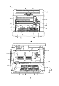
10 of certain
of the embodiments. As seen in Figure 1A, the diagnostic apparatus 10 can
include a fluid,
dispenser 400, mounted on a lateral rail 20. The lateral rail 20 may be part
of a motor-driven
gantry 18, which may also include a fore-aft rail 22 (not shown). The fore-aft
rail 22 may be
connected to the lateral rail 20 and mounted perpendicularly to the lateral
rail 20 in the
diagnostic apparatus 10.
[0063] Figure lA further illustrates the cover 28 over the
heater/optical modules
500a, 500b. Receiving trays 520a and 520b may be located beneath or within the
housing of
the heater/optical modules 500a, 500b. Receiving tray 520a is illustrated in
an open position,
making it available to receive a microfluidic cartridge 200. Receiving tray
520b is illustrated
in a closed position. Closing the tray not only places the reagents in the
appropriate position
for processing, but also further protects the interior of the heater/optical
modules from
receiving any unwanted stray light. Were stray light introduced into the
detection area, the
system may identify erroneous fluorescent levels derived from light which is
not emitted from
the reaction chamber.
[0064] Figure 1B is a perspective view of the diagnostic apparatus
10 showing
certain of the internal components found in certain of the embodiments. To
better illustrate
certain features, the apparatus housing 30, the cover 16, and the
heater/optical cover 28 found
in Figure IA have been removed from view in Figure IB. Shown in Figure I B is
the gantry 18,
including the lateral rail 20 fore-aft rail 22. The fluid dispenser 400 may be
mounted on the
lateral rail 20 and may slide laterally along the long lateral rail 20. The
lateral rail 20 may be
connected to the fore-aft rail 22 which may move in the fore-aft direction. In
this manner the
fluid dispenser 400 is available to move in the X, Y direction throughout the
diagnostic device
10. As described below, the fluid dispenser 400 may also able to move up and
down in the z-
14
CA 2833262 2018-07-05
CA 02833262 2013-10-15
WO 2012/142516 PCT/US2012/033667
plane on the lateral rail 20, thereby giving the dispenser 400 the ability to
move in three
directional degrees throughout the diagnostic device 10.
[0065] Also shown in Figure 1B are the heater/optical modules 500a,
500b with the
cover 28 of the heater/optical modules of Figure IA removed. The receiving
trays 520a and
520b are depicted in the open position and are each holding cartridges 200. In
some
embodiments, the receiving trays may each include a heater substrate 600 (not
shown) beneath
each of the microfluidic cartridges 200. The heater/optical modules 500a, 500b
may also each
include a detector head 700 described in greater detail below.
[0066] As will be described in more detail below, the diagnostic
apparatus 10 may be
capable of conducting real-time diagnostics on one or more samples. The sample
to be tested
may first be placed in a specimen tube (not shown) on the rack 24a or 24b.
Diagnostic reagents
may be located in the holders 26 on the rack 24a inside the diagnostic
apparatus 10. The fluid
dispenser 400 may mix and prepare the sample for diagnostic testing and may
then deliver the
prepared sample to the microfluidic cartridge 200 for thermal cycling and
analyte detection in
the heater/optical modules 500a, 500b. Alternatively, the fluid dispenser 400
may deliver nucleic
acid samples to the reaction chambers of the microfluidic cartridge, wherein
the reaction
chambers of the microfluidic cartridge already contain reagents for an
amplification reaction.
[0067] FIGURE 2 illustrates an interior view of the diagnostic
apparatus 10, showing
the rack 24a holding a number of sample tubes 32 and reagent holders 26, and a
cartridge 200
situated in the receiving tray 520a. The receiving tray 520a is in an open
position extending
from the heater/optical module 500a which has the cover 28 attached. The
receiving tray 520b
is in a closed position. Advantageously, in some embodiments the receiving
trays 520a, b may
allow easy placement of the microfluidic cartridge 200, by a user or by an
auto-loading device.
Such a design may also accommodate multiplexed pipetting of samples using the
robotic fluid
dispenser 400.
Receiving Tray
[0068] As illustrated in Figure 2, the recessed bay 524 can be a
portion* of the
receiving tray 520 that is configured to selectively receive the microfluidic
cartridge 200. For
example, the recessed bay 524 and the microfluidic cartridge 200 can have an
edge 526 which is
complementary in shape so that the microfluidic cartridge 200 is selectively
received in, e.g., a
single orientation. For example, the microfluidic cartridge 200 can have a
registration member
202 that fits into a complementary feature of the bay. The registration member
202 can be, for
example, a cut-out on an edge of the cartridge 200 (as shown in Figure 3A) or
one or more
notches that are made on one or more of the sides. The skilled artisan will
readily appreciate
-15-
CA 02833262 2013-10-15
WO 2012/142516 PCT/US2012/033667
that complementarity between the cartridge and the receiving bay can be easily
achieved using
other suitable arrangements, e.g., a post or protrusion that fits within an
aperture. By selectively
receiving the cartridge 200, the recessed bay 524 can help a user to place the
cartridge 200 so
that the optical module 502 can properly operate on the cartridge 200. In this
way, error-free
alignment of the cartridges 200 can be achieved.
[0069] The receiving tray 520 may be aligned so that various
components of the
apparatus that can operate on the microfluidic cartridge 200 (such as, heat
sources, detectors,
force members, and the like) are positioned to properly operate on the
microfluidic cartridge 200
while the cartridge 200 is received in the recessed bay 524 of the receiving
tray 520. For
example, contact heat sources on the heater substrate 600 may be positioned in
the recessed bay
524 such that the heat sources can be thermally coupled to distinct locations
on the microfluidic
cartridge 200 that is received in the receiving tray 520.
Microfluidic Cartridge
[0070] Certain embodiments contemplate a microfluidic cartridge
configured to
carry out amplification, such as by PCR, of one or more polynucleotides from
one or more
samples. By cartridge is meant a unit that may be disposable, or reusable in
whole or in part,
and that may be configured to be used in conjunction with some other apparatus
that has been
suitably and complementarily configured to receive and operate on (such as
deliver energy to)
the cartridge.
[0071] By microfluidic, as used herein, is meant that volumes of
sample, and/or
reagent, and/or amplified polynucleotide are from about 0.1 1 to about 999
I, such as from 1-
100 I, or from 2-25 I, as defined above. Similarly, as applied to a
cartridge, the term
microfluidic means that various components and channels of the cartridge, as
further described
herein, are configured to accept, and/or retain, and/or facilitate passage of
microfluidic volumes
= of sample, reagent, or amplified polynucleotide. Certain embodiments
herein can also function
with nanoliter volumes (in the range of 10-500 nanoliters, such as 100
nanoliters).
[0072] Figure 3A is a top plan view of a microfluidic cartridge
200. The cartridge
200 may comprise a plurality of sample lanes 1706a-c. The lanes may lead to
PCR chambers
1703 located on "left" and a "right" sides (i.e., rows) of the cartridge. As
indicted in Figure 3a,
the lanes may provide inlet ports 1705 in a convenient location near the user.
However, the
lanes to which the ports are connected may then take independent paths to
separate chambers
1703a-c. In the embodiment of Fig 3a, for example, the first lane 1706a is in
communication
with the first chamber 1703a of the left side, the second lane 1706b is in
communication with
the first chamber of the right side 1703b, the third lane 1706c is in
communication with the
-16-
second chamber 1703c of the left side, etc. Each of the microfluidic lanes may
also comprise
microfluidic valves 1702, 1704, microfluidic gates, and microfluidic channels.
These gates and
valves may be configured, e.g. , by thermal actuation, to facilitate timed
release and controlled
diffusion of certain fluids within the lanes 1706 of cartridge 200. The
cartridge of this
embodiment may comprise venting holes 1701 which prevent air from blocking
fluid passage
within the cartridge. Further description of various cartridge components,
such as valves, may
be found in e.g., U.S. Patent Application Publication 2009-0130719.
[0073] The microfluidic cartridge 200 may include a
registration member 202, for
example, a cutout, which corresponds to a complementary edge in the recessed
bay 524 of the
receiving tray 520a,b of the heater/optical modules 500a, 500b. The
registration member 202
and the complementary edge 526 may allow for secure and correct placement of
the
microfluidic cartridge 200 in the receiving tray 520a, b.
[0074] In various embodiments, the components of a
microfluidic networks in the
sample lanes 1706 of the cartridge 200 may be heated by thermally coupling
them with the
heaters in a heater substrate 600. The heater substrate 600 may be configured
to heat a sample
mixture comprising amplification reagents and an amplification-ready
polynucleotide sample
and cause it to undergo thermal cycling conditions suitable for creating
amplicons from the
amplification-ready sample. The heater substrate 600 may be located on the
cartridge 200 in
some embodiments or in the recessed bay 524.
[0075] The microfluidic network in each lane may be
configured to carry out nucleic
acid amplification, such as by PCR, on an amplification-ready sample, such as
one containing
nucleic acid extracted from a sample. An amplification-ready sample may
comprise a mixture
= of amplification reagents and the extracted polynucleotide sample. The
mixture may be suitable
= for subjecting to thermal cycling conditions to create amplicons from the
extracted
= polynucleotide sample. For example, an amplification-ready sample, such
as a PCR-ready
sample, may include a PCR reagent mixture comprising a polymerase enzyme, a
positive
control nucleic acid, a fluorogenic hybridization probe selective for at least
a portion of the
positive control nucleic acid and a plurality of nucleotides, and at least one
probe that is
selective for a target polynucleotide sequence. The microfluidic network may
be configured to
couple heat from an external heat source with the mixture comprising the PCR
reagent and the
extracted polynucleotide sample under thermal cycling conditions suitable for
creating PCR
amplicons from the extracted polynucleotide sample.
[0076] In various embodiments, the reagent mixture may
comprise fluorescent or
other optically-detectable labels for the detection of the generation of a
desired amplicon. In
-17-
CA 2833262 2019-12-18
CA 02833262 2013-10-15
WO 2012/142516 PCT/US2012/033667
some embodiments, multiple sets of primers and multiple labels can be used in
a multiplex assay
format, e.g., multiplexed PCR, where each of a plurality of different
amplicons can be detected
in a single reaction chamber, if present. For example, one assay chamber could
include template
nucleic acids from a test sample, positive control template nucleic acids, one
or more primer
pairs for the amplification of specific target sequences, one or more probes
for the detection of
target amplicons, and one or more primer pairs and a probe for the detection
of positive control
amplicons. Additionally, the skilled artisan will appreciate that in some
embodiments, the
microfluidic cartridge accommodates a negative control polynucleotide that
will not produce an
amplicon with primer pairs used to amplify target or positive control
sequences.
100771 In certain of the illustrated embodiments, the chambers 1703a-c
respectively
associated with each lane 1706a-c of a multi-lane cartridge 200 may perform
independent
amplification reactions. The results of the reactions for the first column of
chambers (1703a,
1703b) for the first two lanes (1706a,1706b) may then be simultaneously and
independently
measured using a detector head which comprises a "left" and a "right" light
source-
photodetector pair. That is each chamber 1703a-b of each lane 1706a-b may
receive light from a
separate light source and be observed by a separate photodetector
simultaneously. In this
manner, a variety of combinations of reactions may be performed in the
cartridge efficiently.
For example, in some embodiments, a plurality of amplification assays for the
detection of a
plurality target nucleic acids can be performed in one lane, a positive
control and a negative
control in two other lanes; or one or more amplification assays for the
detection of one or more
target nucleic acids, respectively, in combination with an internal positive
control in one lane,
with a negative control in a separate lane. In one particular embodiment, 2,
3, 4, 5, 6, or more
assays are multiplexed in a single lane, with at least that number of
fluorescently distinct
fluorophores in the reaction chamber.
100781 A microfluidic cartridge 200 may be constructed from a number of
layers.
Accordingly, one aspect of the present technology relates to a micro fluidic
cartridge that
comprises a first, second, third, fourth, and fifth layers wherein one or more
layers define a
plurality of microfluidic networks, each network having various components
configured to carry
out PCR on a sample in which the presence or absence of one or more
polynucleotides is to be
determined. In another embodiment, the microfluidic cartridge 200 can comprise
a plurality of
lanes, each including a reaction chamber, etched or molded in a single plane,
such as in a
molded plastic substrate, with each lane being closed by a cover layer, such
as an adhesive
plastic film layer. Embodiments with 8, 10, 12, 14, 16, 18, 20, 22, 24, 28,
30, or more lanes per
cartridge are contemplated. For example, one suitable design is a single
cartridge 200 having 24
reaction chambers, arranged in two rows of 12 reaction chambers, optionally
having relatively
-18-
aligned inlet ports. Further description of various cartridges and their
components may be
found in e.g., U.S. Patent Application Publication 2008-0182301 and U.S.
2009/0130719.
Heater Substrate
[0079]
Shown in Figure 3B is a top plan view of certain embodiments of the heater
substrate 600. Any type of heater can be used, including resistive, Peltier,
or moving-fluid
heaters, with either passive or active cooling contemplated. One of many
possible embodiments
includes a plurality of resistive heaters in thermal contact with each
reaction chamber,
preferably also including one or more temperature sensors. Because resistive
heaters also
exhibit some thermistor effect, i.e., their resistance changes with
temperature, the resistive
heaters themselves can double as temperature sensors, allowing precise
temperature control of
each reaction chamber while simplifying the product design. Although the
heaters can be
controlled in concert with each other, in some embodiments each reaction
chamber can have
one or more individual heaters in thermal contact therewith, such that the
heaters are separately
controllable and each reaction chamber can be heated and allowed to cool
independently of the
other reaction chambers. This allows different assays to be performed
simultaneously in each
of a plurality of reaction chambers. One particular resistive heater assembly
for use with an
individual reaction chamber is shown in Figure 3B. In the embodiment shown in
Figure 3B,
any combination of a top sensor heater/sensor 1604, a bottom heater/sensor
1603, a side
heater/sensor 1601 and a center heater/sensor 1602 may be used to heat the
reaction chamber
located above. For ease of comprehension, an outline of the PCR chamber 1703
of certain of
the embodiments is overlaid on the heater substrate. In certain embodiments,
the heaters in the
heater substrate 600 may be contact heaters. Such contact heaters may comprise
(for example)
a resistive heater (or network thereof), a radiator, a fluidic heat exchanger
and a Peltier device.
The contact heat source may be configured in the recessed bay 524 to be
thermally coupled to
one or more distinct locations of the microfluidic cartridge 200 received in
the receiving tray
520a, b whereby the distinct locations are selectively heated. The contact
heat sources may
each be configured in the heater substrate 600 to be independently thermally
coupled to a
different distinct location in a microfluidic cartridge 200 received in the
receiving tray 520a,b
whereby the distinct locations are independently heated. The contact heat
sources can
advantageously be configured to be in direct physical contact with distinct
locations of a
microfluidic cartridge 200 received in the receiving tray 520a,b. In various
embodiments, each
contact source heater may be configured to heat a distinct location having an
average diameter
in 2 dimensions from about 1 millimeter (mm) to about 15 mm (typically about 1
mm to about
mm), or a distinct location having a
-19-
CA 2833262 2019-12-18
surface area of between about 1 mm about 225 mm (in some embodiments between
about 1
mm and about 100 mm, or in some embodiments between about 5 mm and about 50
mm).
[0080] The heater substrate 600 may be organized into "lanes" 1605a, b
paralleling the structure
of the lanes 1706a-c of the cartridge 200. In some embodiments, the heater
substrate 600 may
include 24 heater lanes 1605a, 1605b corresponding to the sample lanes 1706 of
cartridge 200.
When the microfluidic cartridge 200 is placed in the recessed bay 524 of the
receiving tray
520a,b, the components of the cartridge 200 may be aligned adjacent to, and
above, the
corresponding heaters in the heater substrate 600. When the microfluidic
cartridge 200 is
placed in the recessed bay 524, the heaters may be in physical contact with
the respective
components. In some embodiments the heaters remain thermally coupled to their
respective
components, e.g., through one or more intermediate layers or materials, though
not in direct
physical contact. Further description of lanes may be found e.g., in U.S.
2009/0130719.
[0081] In some embodiments, multiple heaters may be configured to
simultaneously
and uniformly activate to heat their respective adjacent cartridge components
of the
microfluidic network in the microfluidic cartridge 200. Each heater may be
independently
controlled by a processor and/or control circuitry used in conjunction with
the apparatus
described herein. Generally, the heating of microfluidic components (gates,
valves, chambers,
etc.) in the microfluidic cartridge 200, is controlled by passing currents
through suitably
configured micro-fabricated heaters. Under control of suitable circuitry, the
lanes 1706 of a
multi-lane cartridge can then be heated independently, and thereby controlled
independently,
of one another. Furthermore, as is described in more detail below, the
individual heaters 1601-
1604 can be heated independently, and thereby controlled independently, of one
another. This
can lead to a greater energy efficiency and control of the apparatus, because
not all heaters are
heating at the same time, and a given heater is receiving current for only
that fraction of the
time when it is required to heat.
[0082] The heater substrate 600 may also include one or more heat
sensors. In order to
reduce the number of sensor or heaters required to control the heaters in a
heater lanes 1605a,
1605b, the heaters may be used to sense temperature as well as heat, and
thereby obviate the
need to have a separate dedicated sensor for each heater. For example, the
impedance and/or
resistance of some materials change with the surrounding temperature.
Accordingly, the
resistance of heater/sensors 1601 -1604 may be used as an indication of
temperature when the
sensors are not being actively heated.
[0083] In some embodiments, the heaters in the heater substrate 600 may
be designed
to have sufficient wattage to allow the heaters to be grouped in series or in
parallel to
-20-
CA 2833262 2019-12-18
CA 02833262 2013-10-15
WO 2012/142516 PCT/US2012/033667
reduce the number of electronically-controllable elements, thereby reducing
the burden on the
associated electronic circuitry. Heaters that are grouped together in this
manner would be
operated under synchronized and substantially simultaneous control.
[0084] In
some embodiments, the reaction chamber heaters on opposite sides of the
second stage heaters can be grouped and configured to operate under
synchronized control. For
example, in some embodiments, the PCR/amplification heaters 1601-1602 can be
grouped and
configured to operate under synchronized control. Alternative groupings and
configurations can
be applied to other heater groups of the PCR/amplification heaters 1601-1604.
The
PCR/amplification heaters 1601-1604 may be configured to operate individually
and
independently or they can be configured to operate in groups of two (pairs),
three (thirds), four,
five or six.
[0085] In
some embodiments, the heating may be controlled by periodically turning
the current on and off to a respective heater with varying pulse width
modulation (PWM),
wherein pulse width modulation refers to the on-time/off-time ratio for the
current. The current
can be supplied by connecting a micro fabricated heater to a high voltage
source (for example,
30V), which can be gated by the PWM signal. In some embodiments, the device
may include
48 PWM signal generators. In some embodiments there will be two PWM signal
generators
associated with each reaction chamber. Operation of a PWM generator may
include generating
a signal with a chosen, programmable period (the end count) and granularity.
For instance, the
signal can be 4000 us (micro-seconds) with a granularity of 1 us, in which
case the PWM
generator can maintain a counter beginning at zero and advancing in increments
of 1 us until it
reaches 4000 us, when it returns to zero. Thus, the amount of heat produced
can be adjusted by
adjusting the end count. A high end count corresponds to a greater length of
time during which
the micro fabricated heater receives current and therefore a greater amount of
heat produced.
[0086] In
various embodiments, the operation of a PWM generator may also include
a programmable start count in addition to the aforementioned end count and
granularity. In such
embodiments, multiple PWM generators can produce signals that can be
selectively non-
overlapping (e.g., by multiplexing the on-time of the various heaters) such
that the current
capacity of the high voltage power is not exceeded.
[0087]
Multiple heaters can be controlled by different PWM signal generators with
varying start and end counts. The heaters can be divided into banks, whereby a
bank defines a
group of heaters of the same start count. Control of heating elements, and
cooling elements, if
present, in certain embodiments is discussed in further detail below.
Optical Module
-21-
CA 02833262 2013-10-15
WO 2012/142516 PCT/US2012/033667
[0088] Figures 4A-C illustrate the heater/optical module 500 of the
detection
apparatus 10 found in certain embodiments. The heater/optical module 500 may
comprise an
optical module 502 and a receiving tray 520 or a portion of the receiving
tray. Figure 4A shows
one embodiment of the enclosed optical module 502 having a motor 504
externally attached
thereto for driving movement of detector head 700. The detector head 700 may
be housed inside
the optical module 502. Figure 4A illustrates the receiving tray 520 coupled
to a bottom side
506 of the optical module 502. The receiving tray 520 may receive a cartridge
200 comprising
samples upon which detection is to be performed. After receiving the samples,
the receiving
tray 520 may be moved (e.g., mechanically or manually) on rails 522 to a
position underneath
the optical module 502. In some embodiments, described in greater detail
below, the receiving
tray may comprise an auto-loading device, which automatically aligns the
cartridge once
positioned beneath the optical module 502. In some embodiments, a recessed bay
524 of the
receiving tray 520 may contain a heater substrate 600. In some embodiments,
the receiving tray
may subsequently be raised to place the cartridge in contact with the optical
module 502, such as
in contact with an aperture plate 540 at the base of the optical module 502
[0089] Figure 4B illustrates an embodiment of the optical module 502
with a front
panel 508 removed to show the interior of the optical module 502. Shown in
Figure 4B is the
detector head 700. As described in detail below, movement of the detector head
700 may be
driven by the motor 504 to move laterally across the interior of the optical
module 502 to
provide optical scanning and detection on the cartridge 200 when the cartridge
200 is positioned
below the optical module 502 in the receiving tray 520. Shown in Figure 4B is
an aperture plate
540, positioned on the bottom side 506 of the optical module 502.
[0090] Figure 4C provides a bottom plan view of the optical module 502.
Shown in
Figure 4C is the aperture plate 540 and a normalizer plate 546 attached to the
bottom of the 506
of the optical module 502. The normalizer plate may be used to calibrate the
light source ¨
photodetector pairs of the detector head. The normalizer plate 546 preferably
comprises a one or
more components having known, standardized optical characteristics, and is
configured to
calibrate, standardize, or confirm proper operation of the detector head 700
and associated
circuitry. The normalizer plate 546 may extend into the optical module and the
detector head
700 may be positioned over the normalizer plate. In some embodiments, prior to
the start of
cartridge optical measurements the detector head 700 is calibrated using the
known properties of
the normalizer plate 546. If the detector head 700 is not working properly,
corrective action may
be taken, such as including an offset in the measurements or notifying the
user of the error. In
some embodiments, the normalizer plate may be made of optically-transparent
material such as
polycarbonate mixed with a highly fluorescent dye, or other standardized
chromophore or
-22-
CA 02833262 2013-10-15
WO 2012/142516 PCT/US2012/033667
fluorophore. In one embodiment, the normalizer plate includes a standardized
chromophore or
fluorophore for each channel or color in the detector head 700.
[0091] As shown in Figure 4C, the aperture plate 540 contains apertures
557. The
'dimensions of apertures 557 are such that the detector's light sources and
photodetectors may
have access to (optically excite or view) the contents in cartridge 200's
reaction chambers when
the detector is moved to a plurality of positions within optical module 502.
That is, when a light
source-photodetector pair of the detector is located in a position over a
particular aperture light
may travel from the light source and reach the chamber reactor through the
aperture 557. The
fluorescing reagents in the reaction chamber may then be visible to the
photodetector via the
aperture 557.
Detector Head
[0092] Figure 5 shows a cross-section of the detector head 700 taken
along line 13 of
Figure 4B. The detector head 700 may be configured to optically excite and/or
monitor
fluorescence emitted in connection with detection of from one or more
polynucleotides present
in the reaction chambers 1703. Note that a positive result (presence of a
target amplicons) may
be indicated by increased fluorescence or decreased fluorescence, depending on
assay design.
For example, when the assay involves a fluorophore and a quencher, the
quencher may quench
fluorescence when the target is present, or in other assay designs, when the
target is absent. The
system may comprise, for example, a plurality of detector pairs, e.g., 3, 4,
5, 6, 7, 8, 9, 10, 11,
12, 13, 14, 15, 16, 17, 18, 19, 20, 21, 22, 23, 24, or more, such as the
detector pair 726. Each
detector pair 726 can be comprised of a light source 726a, such as a light-
emitting diode (LED),
and a corresponding light detector 726b, such as a photodiode. The light
source 726a may
selectively emit light in an absorption band of a fluorescent probe. The light
detector 726b may
selectively detect light in an emission band of the fluorescent probe, wherein
the fluorescent
probe corresponds to a polynucleotide probe or a fragment thereof In certain
embodiments the
light source 726a may comprise a bandpass-filtered diode that selectively
emits light in the
absorption band of the fluorescent probe. Light detector 726b may comprise a
bandpass filtered
photodiode that selectively detects light in the emission band of a
fluorescent moiety, e.g.,
emission from a fluorescent probe. In certain embodiments, a filter 726a1,
such as a bandpass
filter may be applied to the light source 726a's light. The light from the
light source 726a passes
through a filter before passing through the sample in the micro-fluidic
channel (300g deep in
certain embodiments). In certain embodiments, the optical path-length for the
light from the
reaction chamber to the light detector 726b may be very small. The incident
light from light
source 726a generates fluorescence in the reaction chamber. Light from the
reaction chamber
-23-
CA 02833262 2013-10-15
WO 2012/142516 PCMJS2012/033667
then travels to the light detector 726b. Certain embodiments seek to mitigate
any undesired light
from entering the detector and thereby adversely affecting the light signal
from the reaction
chamber.
[0093] In some embodiments, each one of the plurality of detector pairs
may be
arranged along the length of the detector head 700 in rows. That is, behind
the pairs 726 and
727 illustrated in Figure 5 may be another column of pairs in a similar or
same orientation. For
the sake of explanation, a collection of cartridges or detector pairs along
the length of the
cartridge are referred to as a "row" and those along the width as a "column".
Thus, the vertical
direction in Figures 3A and 6 indicates a "column" and the horizontal
direction a "row". Certain
embodiments contemplate six or more columns of such detector pairs. In these
embodiments,
there would be 12 detector pairs in total (two rows of six) with two detector
pairs per column,
permitting 12 separate and simultaneous detections.
[0094] Each light source, such as for example light source 726a, may be
configured
to produce light of a wavelength specific to a specific fluorescent moiety
associated with, e.g., a
probe, contained in the reaction chambers. Each light detector, such as for
example 726b, may
be configured to detect the light emitted from the fluorescent probes
associated with the light
produced by the light emitter in the detector pair. The detector pairs may be
configured to
independently detect a plurality of fluorescent moieties, e.g., different
fluorescent probes, having
different fluorescent emission spectra, wherein in each reaction chamber,
emission from each
fluorescent probe is indicative of the presence or absence of one particular
target polynucleotide
or a fragment thereof Although folded light paths can be used, one embodiment
utilizes a
detector and emitter pair where each is in direct optical contact with the
reaction chamber,
preferably simultaneously in such contact. Optionally, the detector and
emitter of a pair are
aligned with the reaction chamber along lines that substantially intersect at
an acute angle at the
reaction chamber. The angle can be, for example, between about 5 and 70
degrees, preferably
between about 8 and 60 degrees, more preferably between about 10 and 50
degrees.
[0095] In some embodiments, the detector head includes two rows of
photodetector
and light source pairs that correspond to two rows of reaction chambers of
microfluidic
cartridges, when present in the apparatus. For example, the detector head can
include a first or
top row of six photodetector and light source pairs, and a second, or bottom
row of
photodetector and light source pairs, that are configured to query first and
second rows of
reaction chambers within a microfluidic cartridge, respectively.
[0096] Figure 6 illustrates one possible photodetector and light source
layout
implemented in certain embodiments of the detector. The first column comprises
ROX light
emitters 201a, 201b and corresponding detectors 207a, 207b. The second column
comprises
-24-
CA 02833262 2013-10-15
WO 2012/142516 PCMJS2012/033667
HRM light emitters 201c, 201d and corresponding detectors 207c, 207d. The
third column
comprises CY5 light emitters 201e, 201f and corresponding detectors 207e,
207f. The fourth
column comprises FAM light emitters 201g, 201h and corresponding detectors
207g, 207h.
The fifth column compriscs Q705 light emitters 201i, 201j and corresponding
detectors 207i,
207j. The sixth column comprises VIC light emitters 201k, 2011 and
corresponding detectors
207k, 2071. In some instances, the detectors and emitters are selected with
reference to particular
fluorophores to be used in an assay. In the embodiment illustrated in Figure
6, the first or top
row detector and light source pairs comprises a plurality of photodetector and
light source pairs,
e.g. emitters 201a, 201c, 201e, 201g, 201i, and 201k and detectors 207a, 207c,
207e, 207g, 207i,
and 207k. The second or bottom row detector and light source pairs comprises a
plurality of
photodetector and light source pairs, e.g. emitters 201b, 201d, 201f, 201h,
201j, and 2011 and
detectors 207b, 207d, 207f, 207h, 207j, and 2071. A summary of the properties
of exemplary
emitters and detectors is shown in Table 1 below.
TABLE 1
Wavelength Name
Color (Spec) Dye (Assay) (Ex/Em) Software CT#
Green FAM 470/510 FAM 4
Yellow TET, VIC 530/555 VIC 6
Orange Texas Red, ROX 585/610 Cal Red / ROX 1
Red Cy5 625/660 Cy5 3
Crimson Cy5.5 680/715 Cy5.5 5
ultraviolet null ultraviolet HRM 2
[0097] The exemplary arrangement of photodetectors and light sources
depicted in
Figure 6 can inhibit cross-talk between detection columns. That is, the
wavelength range for
each emitter detector pair may be selected so as to possess a minimal overlap
with its
neighboring emitter-detector pairs. Thus, for example, where CT# refers to the
column of a
particular emitter-detector pair in a 6-column detector head, Ex is the
excitation wavelength of a
fluorophore, and Em is the emission wavelength, it will be apparent that
adjacent emission
wavelengths are not adjacent to each other in the detector head. That the row
HRM's dye is null
merely indicates that a variety of dyes, not required for this particular
example, may be used. In
some embodiments, HRM refers to a "High Resolution Melt" and a corresponding
light source
for this photodetector may comprise an LED operating in the ultraviolet
spectrum. One will
recognize that the columns may be arranged in alternative variations and that
alternative
selections of light emitting sources and detectors may be substituted for
those shown.
[0098] The light-emitter and photodetector pairs of each column may be
calibrated
using the normalizer plate. After calibration, the detector head may be moved
to a position such
that a first column of light-emitter and photodetector pairs is located over a
first group of lanes
-25-
CA 02833262 2013-10-15
WO 2012/142516 PCMJS2012/033667
such that each light-emitter and photodetector pair has access to a reaction
chamber of the lanes.
Detection of the reaction chambers in the first group of lanes will then be
performed using the
first column of emitters/detectors. Then, the detector head may be moved to a
second position
such that the first column is over a second group of lanes and the second
column is over the first
group of lanes. Detection of the reaction chambers in the second group of
lanes will then be
performed using the first column of emitters/detectors and detection of the
reaction chambers in
the first group of lanes will then be performed using the second column of
emitters/detectors.
The process may continue until each column has passed over each lane. Thus,
for N columns of
detectors and M columns of chambers, the detector will perform detections at
least M + N ¨ 1
positions. For example, in the embodiments of Figure 11 there are 6 columns.
For a cartridge
comprising 12 lanes, the detector would need to move between at least 17
positions (18 if the
calibration position is considered).
100991 Figure 7 depicts the final results after operation of certain of
the
embodiments. Plotted are the detected fluorescent levels for each light
emitter ¨ photodetector
pair 801-805 over time for a single reaction chamber (or reactor) associated
with a single lane.
After a sufficient number of iterations (approximately 30 in this example) of
the annealing and
denaturing protocol, the detectors identify increasing levels of fluorescence
within the reactor.
Chamber Plate
[0100] Certain of the present embodiments relate to the plating
surrounding and
including the chamber layer. Particularly, certain embodiments contemplate the
manufacture of
an aperture layer comprising characteristics that advantageously facilitate
consistent results
across trials of the heating/detection module, as discussed in further detail
below.
[0101] Figure 8 illustrates the plating arrangement found in certain
embodiments of
the scanning thermocyler's optical module and the associated receiving tray
and cartridge.
When the cartridge is brought within proximity of the aperture layer 540 of
the optical module
500a, the thermal layer 600, chamber layer 200 (which may comprise a chamber
substrate), and
aperture layer 540 may be situated as depicted in the embodiment of Figure 8.
As discussed
above, the chamber layer 200 may comprise a plurality of reaction chambers
1703a-d, which
may be located so as to be thermally controlled separately from one another,
or in groups.
Thermal layer 600 may comprise a plurality of thermal units 1605a, 1605b,
1605c. Figure 8 is a
simplified, abstract diagram of the above description, and certain features of
the microfluidic
pathway are not shown. In certain embodiments the thermal units may be both
mechanically
and thermally disconnected from one another (as illustrated by their physical
separation in
Figure 4). However, in other embodiments, the thermal units may be each placed
within a same
-26-
CA 02833262 2013-10-15
WO 2012/142516 PCT/US2012/033667
substrate material, but spaced such that they remain thermally disconnected,
as discussed above.
Thus, it is possible for the thermal units to be thermally separated, but not
mechanically
separated.
101021 In this manner, each thermal unit may be associated with one or
more
reaction chambers 1703a-d, separately from the remaining reaction chambers. In
agreement
with the protocol specified for each reaction chamber, the thermal units may
successively heat
and/or cool their corresponding chamber appropriately. For example, thermal
unit 1605c may
cool and/or heat chamber 1703a such that the temperature of chamber 1703a is
substantially ,
independent of the cooling and thermal state of the chamber 1703a. While
heating may be
accomplished by running current through a microfluidic or electronic circuit,
cooling may be
"passive" in that only convection between the microfluidic chamber and is used
to reduce the
chamber's temperature. The thermal units 1605a, 1605b, 1605c may be controlled
using a
closed loop control system.
101031 In some embodiments, aperture plate 540 may be located over the
chamber
layer 200 and can provide pressure to chamber layer 200 to facilitate heating
and cooling of the
microfluidic cartridge, e.g., the chamber layer, by thermal layer 600. The
aperture plate can
include a plurality of apertures 557a-d to facilitate each photodetector's
726b observation of an
individual reaction chambers 1703a-d. In the absence of aperture plate 540,
and depending on
the configuration of the thermal layer 600 and chamber layer 200, chamber
layer 200 may
"warp" and/or be sufficiently flexible that the thermal communication between
chambers and the
respective thermal units is inconsistent. Inconsistent heating and cooling can
lead to less
accurate execution of the protocols and less precise and accurate results. As
described above,
significant warping may restrict the optical head from lateral movement. Thus,
the thickness of
the aperture plate must be appropriately selected to facilitate a proper light
path between each
reaction chamber and the light sources and photodetectors while still ensuring
proper heating
and cooling of the chamber layer. If the aperture layer is too thick, the
distance from the
photodetector 726b to the chamber may be too great, undesirably attenuating
the fluorescence
reading from the reaction chamber. In addition to increasing the distance to
the reaction
chamber, an aperture layer 540 which is too thick or too heavy will place too
much pressure on
the reaction chamber, causing convection to be too great. Conversely, if the
aperture layer 540
is too thin it may not prevent the chamber layer 200 from bending and warping,
and the aperture
layer 540 may bend and warp itself. Warping of apertures 557a-d or the
chambers 1703a-d may
deflect light from the light source 726a and prevent accurate readings by
photodetector 726b.
[0104] Accordingly, the embodiments described herein provide aperture
layers that
advantageously avoid the drawbacks described above. In certain embodiments,
the aperture
-27-
CA 02833262 2013-10-15
WO 2012/142516 PCMJS2012/033667
layer 540 is made, at least in part, of steel. In these embodiments, steel
provides the appropriate
strength, density and resistance to deflection desired for operation.
Furthermore, the steel may
provide low self-fluorescence and is therefore less likely to adversely affect
the reading of
photodetector 726b. The steel may also be electrochemically treated to
diminish its self-
fluorescence and thereby be less likely to adversely affect the reading of the
photodetector. In
certain embodiments, the aperture layer may instead comprise black nickel
(Ni), i.e. Ni with a
colorant added to it to reduce self-fluorescence.
Certain embodiments contemplate
combinations of these different materials and electrochemical treatments.
In certain
embodiments, the aperture layer 540 is made of aluminum and when secured by
the adjoining
support panels 500, 506, and 546, provide the appropriate strength. The
aluminum may be
electrochemically plated with an anodic oxide finish, e.g., with a black
colorant added to reduce
self-fluorescence.
[0105] The
illumination optics may be designed so that the excitation light falling on
the reaction chamber, or reactor, is incident along an area that is similar to
the shape of the
reactor. As the reactor may be long and narrow, the illumination spot may also
be long and
narrow, i.e., extended, as well. Thus the shape of apertures 557a-d may be
designed with
consideration both to the dimensions of the reaction chamber underneath, as
well as to the
relative positions of the corresponding light emitter and photodetector. The
length of the spot
may be adjusted by altering a number of factors, including: the diameter of
the bore where the
photodetector 726b is placed (the tube that holds the filter and lens may have
an aperturing
effect); the distance of the photodetector 726b from the PCR reactor; and the
use of proper lens
in photodetector 726b.
Force Member
[0106] In
certain embodiments, the receiving tray 520 places the chamber layer 200
in proximity to the thermal layer 600 or aperture layer 540, but does not
mechanically couple
and/or thereby place the layers in contact with one another. In this manner,
the chamber layer
200 may be thermally, but not mechanically, coupled to the thermal layer 600.
In other
embodiments, the receiving tray places the thermal layer 600 in both
mechanical and thermal
contact with the chamber layer 200 and the chamber layer in mechanical contact
with the
aperture layer 540. In various embodiments, the apparatus may include one or
more force
members (not shown) that are configured to apply pressure to the receiving
tray 520 in order to
thermally couple the heat sources to the microfluidic cartridge 200 positioned
in the receiving
tray 520. The application of pressure may be important to ensure consistent
thermal contact
between the heater substrate and the reaction chambers, gates, and valves,
etc., in the
-28-
CA 02833262 2013-10-15
WO 2012/142516 PCT/US2012/033667
microfluidic cartridge 200. When the receiving tray 520 is in a closed
position, thereby being
positioned under the aperture plate 540 of the optical module 502, the force
member, such as a
motor assembly, below the receiving tray 520 may begin traveling upwards
towards the optical
module 502, thereby bringing the receiving tray 520 closer to the optical
module 502. As the
receiving tray 520 travels upwards towards the optical module 502, the
cartridge 200 may begin
to come in contact with a bottom surface of the aperture plate 540. The
cartridge 200 may
continue traveling upward until sufficient pressure is received on the
cartridge 200. As
discussed above, the aperture plate 540 may apply an equal pressure across all
points of the top
of the cartridge 200 and thus, presses the cartridge 200 against the heater
substrate 600 with
uniform pressure. As discussed, the aperture layer may be selected to possess
properties which
facilitate this operation. For example, the material selection of the aperture
plate 540 may
provide very little deflection of the cartridge 200, when pressed against it.
[0107] The
application of uniform pressure of the cartridge 200 against the heater
substrate 600 may allow for uniform heating for each of the components of the
cartridge when
desirable. Although uniform pressure and contact may be obtained between the
heaters in the
heater substrate 600 and the components (valves, gates, chambers, etc.) of the
microfluidic
networks in the cartridge 200, the heaters are not necessarily activated
simultaneously, as
discussed above. In certain embodiments, application of even pressure does not
necessarily
result in equal heating of different components of the cartridge 200. In some
embodiments, both
the activation of a specific heater in the heater substrate 600 along with the
pressure applied by
the aperture plate 540 to the cartridge 200 activate a particular component of
cartridge 200.
[0108]
Figures 9A-H are diagrams of the dimensions of one possible
embodiment of the aperture plate. In this embodiment, a chemical conversion
coat may be
applied to adjust the reflective properties of the aperture layer. Some
portions 9002 may be
selected not to receive the chemical conversion coat. The coating may be
applied to the surface
of plate 540 or deposited throughout its material. In some embodiments, the
material of the
plate 540 may comprise steel. In other embodiments, the plate 540 may comprise
aluminum. In
yet other embodiments, the material of the plate 540 may comprise nickel. In
some
embodiments, the material of the plate can be a combination of two or more
materials, including
for example, aluminum, nickel, or steel.
[0109] In
the embodiment shown in Figures 9A-H the dimensions of the plate have
been selected to meet the constraints regarding chamber pressure and optical
path to the detector
pairs discussed above. The material thickness of the plate 540 starts out at
0.3125 inches and is
machined down to the desired thickness. As indicated, much of the plate
comprises a thickness
of approximately 0.25 inches. However this thickness may vary, for example,
the thickness over
-29-
CA 02833262 2013-10-15
WO 2012/142516 PCMJS2012/033667
the aperture openings 557 may be 0.19 inches. As discussed above, the aperture
opening
thickness facilitates an unimpeded optical path between the photodetector and
light source to the
contents of the reaction chamber.
101101 In general the dimensions of the aperture plate 540 are selected
such that in
combination with the properties of the materials constituting the aperture
plate 540, the plate 540
provides sufficient pressure to the underlying chamber plate to facilitate
proper heating and
cooling as well as sufficient rigidity to prevent warping or deformation of
the chamber plate.
Such deformation may result in obstructions to the light source and
photodetector optical path to
the reaction chamber. Simultaneously, the dimensions of the plate should not
impose an
unfavorable distance from the reaction chamber of the chamber layer to the
light-source and
photodetector pair through the apertures 557. Neither should the aperture
plate's dimensions
540 obstruct the optical path from the light-source and photodetector pair to
the contents of the
chamber reactor.
101111 In some embodiments the normalizer plate 546 may be attached to
the
aperture plate by inserting screws at positions 9001 or other fixation means
through an aperture.
In other embodiments, these positions may facilitate broader calibration
techniques via the
apertures over the normalizer plates than with regard to the remaining
apertures.
[0112] Figure 10 illustrates various dimensions of the perspectives of
the aperture
plate of Figures 9A-H. As discussed above, in this embodiment, a chemical
conversion coat
may be first applied to prevent the base materials, e.g., aluminum, nickel or
steel, from oxidation
while also providing enhancing electrical grounding for proper electronics
operation. Only
surfaces which may be exposed to the optical operation are then selectively
coated with black
anodization.
Diagnostic Analysis Consistency
[0113] Certain of the present embodiments contemplate methods for
ensuring
consistent diagnostic analyses across trials within the same heater/detector
and across different
heater/detectors. Particularly, embodiments of a system and process for
determining the
duration and offsets for a plurality of PCR protocols so as to synchronize
detection therebetween
are disclosed. Additionally, methods for adjusting the reactor cooling time to
ensure more
consistent results are discussed.
101141 Figure 11 is a temperature profile for a reaction chamber
undergoing a
particular protocol 2000. As illustrated above, the system in operation may
comprise many
different protocols of many different durations operating simultaneously in
different reaction
chambers. The protocol 2000 involves a plurality of identical heating/cooling
cycles, where
-30-
CA 02833262 2013-10-15
WO 2012/142516 PCT/US2012/033667
each cycle comprises denaturing plateaus 2000B and annealing plateaus 2000D
where the
temperature is maintained constant for a period of time. These cycles may be
preceded by a
non-periodic cycle of the protocol, such as an incubation period. In certain
embodiments, the
protocol may be specified as a collection of temperatures and periods of time.
That is, the
protocol may initially specify only that the chamber is to be held at 95 C for
the duration B and
then held at 61 C for the duration D. Certain embodiments contemplate grouping
these
segments into "steps" and "substeps" to facilitate user and automated control.
For example, the
heating and cooling cycle 2000B and D may be referred to as a "step" with the
duration B at
95 C and the duration D at 61 C referred to as "substeps". In certain
embodiments, a user may
specify the durations of the substeps. In other embodiments, these durations
may be retrieved
from a database. Typically, these times are established either from a standard
protocol or by
user input, sometimes using an established "recipe" of temperatures and
plateau times. In
addition to these substeps, the protocol's temperature profile will also
comprise transitions, such
as transition 2000A from 61 C to 95 C and transition 2000C from 95 C to 61 C.
The duration
of these transitions may be a consequence of the materials and environment
about the reaction
chamber and the nature of the heating elements employed.
101151 In certain embodiments the thermal trajectory for both heating
and cooling
may be determined for the entirety of the reaction prior to the start of the
run. In some systems,
the contour of temperature versus time is monitored and adjusted throughout
the reaction in
order to minimize transition temperatures, and taking into account the
variations in efficiencies
of different heating elements. In other words, some systems utilize feedback
control loops to
drive to a target temperature, wherein the actual contour of the temperature
time relationship can
vary from cycle to cycle. Such adjustments can result in different overall
reaction times, and,
more importantly, different overall reaction efficiencies. Accordingly, in
some embodiments,
the systems and methods described herein advantageously provide systems
wherein the contour
of the temperature versus time relationship of the complete reaction for each
independent
reaction chamber (or group of chambers) is predetermined set prior to the
start of the run. Not
only does this advantageously allow for synchronization of the multiple
detection steps across a
plurality of different reactors, but it also enables for stricter control over
parameters that
minimize differences in reaction efficiencies that may arise as a result of
different
temperature/time contours. In some embodiments, the systems and methods
provided herein
provide for the report of errors at the end of a reaction if the measured
temperature is different
from the expected value when a run is completed.
101161 At various points in the protocol temperature profile 2000, the
user or recipe
may specify that a detection occur. For example, for some protocols a
detection may be
-31-
CA 02833262 2013-10-15
WO 2012/142516 PCT/US2012/033667
requested at the end of segment 2000D. Were detections arbitrarily specified
in each protocol,
the detector head would need to travel between positions in an inefficient
manner and may even
find it impossible to perform detections at the requested times. That is, were
each of a plurality
of protocols to be initiated simultaneously and run in parallel simultaneously
across each of the
reaction chambers in the cartridge, it would be very inefficient for the
detector to meet each
protocol's detection requests. Particularly, once calibration was complete the
detector would
need to first travel to positions suitable to perform detections for each
light source-detector pair
in its array for the first profile. By the time the detector finished,
however, each of the
remaining protocols would be entering a period when detection is not to be
performed. There
will therefore be a "dead time" period when the detector cannot perform any
detections and must
instead simply sit idle waiting for the opportunity to perform the next
detection. This "dead
time" is inefficient and unnecessarily prolongs the diagnostic process.
Furthermore, where
successive detections are to be performed, the "dead time" may generate
irregular and aperiodic
detections of the same chamber, possibly introducing inconsistent readings.
[0117] Certain of the present embodiments contemplate automated
adjustments to
portions of the profile 2000 to facilitate efficient detection across multiple
protocols. This may
be accomplished by allowing the user to edit, or the system may edit
automatically, the length of
segment 2000B or 2000D.
[0118] It should be understood that so long as at least a minimum
plateau time
occurs, some minor extension of plateau times can be accommodated in most
amplification
protocols. This flexibility is utilized to all efficient accommodation of
different assays being
performed simultaneously, while performing real-time monitoring of
amplification by reading
the various assays using a scanning detector head.
[0119] If detection were to be performed during segment 2000B, for
example, the
system or the user may extend the duration of segment 2000B as necessary to
accommodate
detector head movement and to coordinate the reading of a plurality of assays
being performed
simultaneously. The duration of segments 2000A and 2000C may be calculated
using a
predetermined standard cooling rate from the preceding temperatures and
incorporated into the
analysis. Some embodiments do not allow the user to edit these segments and
they are instead
accounted for by the system internally.
[0120] In certain embodiments, the protocol adjustments determined by
the system
may comprise at least three separate forms. The first adjustment may comprise
an "intra-cycle
adjustment" wherein plateaus such as 2000B and 2000D of the protocol are
extended such that
the entire step cycle 2000A-D achieves a desired duration, in some instances
an integer multiple
of a detection cycle time. This adjustment is described with respect to Figure
13. Once the
-32-
CA 02833262 2013-10-15
WO 2012/142516 PCMJS2012/033667
intra-cycle adjustment is complete, the system may then perform an "inter-
cycle adjustment".
An inter-cycle adjustment may ensure that detection events within each cycle
occur at integer
multiples of a desired duration apart from one another (such as an integer
multiple of the
detection cycle time) between the cycles. These adjustments are discussed with
regard to Figure
14. The third adjustment may comprise a "starting offset adjustment" which may
depend only
on the lane used for protocol execution. These adjustments are discussed with
respect to Figures
15A-C.
Protocol Adjustment Overview
[0121] Figure 12 depicts a flow diagram of a process 4000 used in
certain of the
disclosed embodiments to determine an appropriate solution for the detector
detection times and
protocol profiles. Process 4000 may be implemented in software, hardware, or a
firmware
combination of the two. For example, the process may be implemented in any of
an FPGA, a
mierocontroller, or software running on a computer processor. Portions of the
process may be
performed by a general purpose processor, such as a microcontroller, while
other portions may
be performed by dedicated hardware, software, or firmware systems. The process
begins 4001
by determining a detection cycle time (or using a predetermined detection
cycle time, e.g.,
already in memory) for the system 4002. The detection cycle time may comprise
the time that is
required for the detector to move to each of the detection positions
(detection with each of the
emitter/detector pairs in a detection head in each of the six columns of
Figure 6), perform all
necessary detections, and return to an initial position. Optionally, the user
or system may be
allowed to make adjustments to the detection procedure so as to modify the
detection cycle time.
For example, the user may wish to only perform detection using a subset of the
detectors. In
some embodiments the detection cycle time is approximately 10 seconds, when
the embodiment
comprises six columns of detector pairs and all six columns are used.
[0122] In some embodiments, the process may first determine a plurality
of "intra-
cycle adjustments" for one or more of the protocols 4003. As discussed below
with respect to
Figure 13, the durations for a step or substep may comprise the time to
perform a particular step
or substep within the protocol. The cycle times may be determined by a
combination of user
specifications and system identified constraints. In certain embodiments, the
system will require
the plurality of cycle times to be integer multiples of the detection cycle
time. "Intra-cycle
adjustments" may be introduced to satisfy this constraint. For example, if the
detection cycle
time were 12.2 seconds, the cycle times for a protocol step may be 22.4, 33.6,
44.8, or any other
N * 12.2 duration, where N is an integer greater than 0. In some embodiments,
it is only
necessary to impose this constraint when a detection is to be performed within
the cycle.
-33-
CA 02833262 2013-10-15
WO 2012/142516 PCMJS2012/033667
101231 Thus, intra-cycle adjustments ensure that the cycle of the
protocol is an
integer multiple of the detection cycle time. However, a detection may be
requested at any point
within a cycle. If the detection cycle time is 10 seconds, then the very
earliest that a detection
may be performed is at 10 seconds after the protocol initiates. Detections may
then be
performed at integer multiples after that time (20, 30, 40 seconds, etc.).
[0124] Thus, a further adjustment, an "inter-cycle" adjustment 4004, may
then be
determined to ensure that the requested detection occurs at the appropriate
time. These "inter-
cycle adjustments" may be incorporated into the protocol as additional delays
between protocol
steps or substeps. Phrased differently, a PCR protocol once subjected to
"intra-cycle"
adjustments may comprise "valid" cycle steps. The PCR protocol may then be
generated by
chaining together each of the steps and adding transitions from step to step.
The "inter-cycle
adjustments" 4004 ensure that the detection times occur at the desired integer
multiples of the
detection cycle time after the cycles have been chained together.
[0125] For example, for a system having a detection cycle time of 10
seconds a
protocol may comprise a step having its first detection at 18 seconds into a
cycle. The cycle
duration (the duration of the entire step) may last for 30 seconds (perhaps
after an "intra-cycle"
adjustment). Thus, while the cycle time as a whole is properly aligned with
the 10 second
detection cycle time (3 x 10 = 30 seconds) the first detection is itself not
properly aligned with
the detection (18 second is not a multiple of 10 seconds). The system will add
2 seconds of
"inter-cycle" adjustment to the very first detection run so that the first
detection occurs 20
seconds after the start of the protocol. This may be done by extending the
previous step's final
hold temperature for an additional 2 seconds via a "padding adjustment". If
there is no previous
step, the system would insert a 2 second hold at ambient temperature to the
beginning of the first
run of the cycle. Thus, if the system begins operation at TO, the first
detection will occur at TO +
20 seconds, the second detection at TO + 50 seconds, and so forth.
[0126] Because of the inter and intra-cycle adjustments, the protocol is
now in a
form such that detections will only be requested at times convenient for the
detector head to
move to the reaction chamber performing the protocol. Were all protocols
performed in reaction
chambers located in the first column of the cartridge (and sufficient number
of detectors present
in the detector head) intra and inter-cycle adjustments alone would suffice to
properly modify
the protocol for efficient detection (a first column here referring to a
column of lanes such as
lanes 1706a and 1706b with associated chambers 1703a and 1703b in Figure 3A).
However,
because the protocols operate in different columns of the cartridge it is
further necessary to
offset the protocol's initiation to compensate for the detector head's delay
in reaching the
chamber location.
-34-
CA 02833262 2013-10-15
WO 2012/142516 PCMJS2012/033667
[0127] Thus "starting adjustment offsets" are added to the protocol
based on the
location of the chamber in which the protocol is performed. These "starting
adjustment offsets"
4005 are described in greater detail with respect to Figures 15A-C. In some
embodiments, these
adjustments are made at run time and rely solely on the location of the lane
of execution. For
example, no adjustment may be necessary for a protocol running in lanes
located in a first
column of the chamber, so a protocol run in these lanes' chambers will have a
delayed start time
of +0 seconds. Each subsequent column of lanes gains a delay of 400
milliseconds for its
distance from the first column, due to the time required for the detections
(two detections at 100
milliseconds each, performed asynchronously in this embodiment) and the
detector motor
movement (200 milliseconds). In this example, with a detection cycle time of
10 seconds, the
first possible detection for each column of lanes is as follows: column 1 has
its first detection at
seconds, column 2 has its first detection at 10.4 seconds, column 3 has its
first detection at
10.8 seconds, etc. By delaying the start of a properly aligned protocol by the
necessary time for
a particular lane, the expected alignment can be maintained. While this
particular example
assumes that the protocol is already aligned (from adjustments 4003 and 4004),
the skilled
artisan will readily appreciate that other embodiments may determine the
offsets anticipating
future adjustments.
[0128] Although described in the order of steps 4003, 4005, and 4004,
one will
readily recognize that these steps may be arranged into any other suitable
order, and neither need
the system perform each step successively. In some embodiments, however, such
as that
described above, it may be necessary to perform inter-cycle adjustments after
performing intra-
cycle adjustments, as the inter-cycle adjustment depends on the intra-cycle
modification. In
contrast, the starting-offset adjustment 4005 may not depend on any previous
determination.
That is, in some embodiments the starting offset 4005 need be determined only
once at run time,
whereas the intra-cycle adjustments 4003 and inter-cycle adjustments 4004 may
be performed
for each cycle step in the protocols.
[0129] In some embodiments, once the protocol times have been properly
adjusted,
the process may then initiate the protocols 4006. In some embodiments a
processor may simply
place the offsets in a memory location for retrieval by a separate dedicated
component of the
system which itself initiates each protocol.
I ntra-Cy cle Adjustment
[0130] "Intra-cycle adjustments" comprise adjustments to step or substep
intervals,
as may have been specified by a user or received from a database, so that the
step as a whole is
an integer multiple of a predetermined duration. With reference to Figure 13
in certain
-35-
CA 02833262 2013-10-15
WO 2012/142516 PCMJS2012/033667
embodiments the user may specify certain features of the protocol profile,
such as the desired
times for a protocol substep, using a user interface, or graphical user
interface (GUI). In some
embodiments, the system may then validate the user's selection. After
calculating segment
lengths for each of the substeps, the system software will validate the step
cycle time and
indicate if any adjustments are necessary. In some embodiments a "valid" step
cycle time is a
step cycle time that is an integer multiple of the detection cycle time. If a
step cycle time is not
valid, the user may be prompted to make adjustments for that step 5003b. If no
adjustment is
necessary, the user may be notified that the step is aligned properly 5003a.
[0131] In the example of Figure 13, the user has required an
incubation step 5001
comprising a single substep of 900 seconds. The user has requested that the
step 5001 occur
only once 5010 and therefore comprises a single step cycle. In this example,
the detection cycle
comprises 10 seconds. The user has not specified that any detection is to be
performed and
accordingly the step is valid, since the step will not require that the
detector head's position be
adjusted. When no detection is requested the system records the requested time
intervals, for
future offset considerations, but may not impose any constraint that the time
interval be a
multiple of the detection time (though the duration may be considered in
determining a
subsequent inter-cycle adjustment). If, however, in this example the user had
requested
detection during this step, the step would still be valid if no other delays
are incurred, as 900
seconds is a multiple of the 10 seconds detection cycle. In either event, in
the illustrated
embodiment, the system has determined that this step entry is valid.
[0132] In the example illustrated in Figure 13, the step PCR 5002
comprises two
substeps, a first substep where the chamber is to be held at 95 C and another
substep where the
chamber is to be held at 61 C. The user has requested that 45 cycles of this
step be performed
5011. The user has requested that the first substep last 2 seconds and that
the second substep
last 10.2 seconds for a total of 12.2 seconds. As discussed above with respect
to Figure 7, the
- system may have also calculated the transition time from 95 C to 61 C and
added this duration
to the user requests. In this example, heating from 61 C to 95 C requires 4.25
seconds and
cooling from 95 C to 61 C in 7.05 seconds. These values may be stored
internally in the
system's memory or determined dynamically based on the user inputs. Finally,
in some
embodiments, when a detection is requested for a substep 5004, as the user has
requested here,
the system adds an additional delay to the hold time for that substep. In this
example, that delay
is 2.2 seconds, which accounts for the minimal time required to allow the
detector to move and
detect with each of six columns of light emitter-photodetector pairs in the
detector head. That is,
in this example, each color detection requires 200 milliseconds of exposure
time and 200
-36-
CA 02833262 2013-10-15
WO 2012/142516 PCMJS2012/033667
milliseconds to move the motor between columns (5 transitions * 200ms + 6
detections * 200ms
= 2.2 seconds).
101331 Thus, the total duration for the step as a whole is:
101341 4.25 (heat) + 2.0 (denature) + 7.05 (cool) + 10.2 (anneal) + 2.2
(detection)=
25.7 seconds.
[0135] As 25.7 seconds is not a multiple of the 10 second detection
time, adjustment
will be necessary. As indicated 5003b, the system informs the user that they
may either remove
5.7 seconds from the step duration or add an additional 4.3 seconds to achieve
a multiple of the
detection cycle time (i.e., a multiple of 10 seconds). These "intra-cycle step
adjustments" will
be incorporated into the protocol after the user's selection.
[0136] One will recognize that the system may consider a plurality of
other factors
not indicated in this example when providing the user with an adjustment
range. For example,
additional delays to motor movement or incubation preparation may be factored
in to the
system's analysis.
Inter-Cycle Adjustments
[0137] As mentioned above, "inter-cycle adjustments" comprise
adjustments to the
first cycle of a substep so as to create a delay between cycle steps. "Inter-
cycle adjustments"
may depend on the timing of the preceding steps and the end temperature of the
immediately
preceding step (if one exists). With reference to Figure 14 the "inter-cycle
adjustment" 6005
determined to achieve a proper detection time occurrence, will be described.
[0138] In some embodiments the adjustment 6005 is determined by first
determining
the time required to heat or cool the temperature from the end of the previous
step to the first
substep temperature of the next step. If any additional time is necessary for
alignment, the
temperature from the end of the previous step may be maintained for this time.
An example of
alignment between the end temperature of a hold step at 75 C to the first
substep temperature of
95 C is shown in Figure 14. The temperature is ramped at 8 C/s from 75 C to 95
C from points
6001b to 6001c, with the remaining time required for alignment spent holding
at 75 C after the
end of the previous step, from points 6001a to 6001b. This period may be
referred to as an
"inter-cycle adjustment". To achieve continuance of detection alignment
between steps, it may
be necessary to shift (or delay) the start of a step cycle after the end of
the previous step by this
"inter-cycle adjustment". The time required to heat or cool the temperature
from the end of the
previous step to the first substep temperature of the next step may then be
calculated. If any
-37-
CA 02833262 2013-10-15
WO 2012/142516 PCMJS2012/033667
additional time is necessary for alignment, the temperature from the end of
the previous step is
maintained for the time of the "inter-cycle adjustment". In some embodiments,
the system may
factor in these considerations when receiving user input via GUI 5000 and
incorporate them into
the proposed variance 5003b.
Starting Offset Adjustments
101391 Figure 15A illustrates the beginning cycles of two separate
protocol profiles
3001 and 3005. In each of these protocols the inter and intra-cycle
adjustments may have been
performed, but the starting offset has yet to be applied. In this example,
profile 3001 includes a
step with a cycle time of 30 seconds (the interval from time 0 to time 30). A
time for detection
3020a, or a detection request occurs 30 seconds. Note that pursuant to the
inter-cycle
adjustments discussed above, a small delay may have been included in the
protocol 3001 just
prior to the first heat ramp for alignment of the first detection 3020a. As
discussed above, the
inter-cycle and intra-cycle adjustments facilitate detection requests being
made at integer
multiples of the detection cycle time. Here, for a detection cycle time of 10
seconds, the
requests 3020a and 3020b occur at the integer multiples 30 and 60 seconds.
[0140] The second protocol 3005 includes a different profile from 3001.
The profile
3005 comprises an initialization step lasting from 0 to 30 seconds. The
profile 3005 is then
followed by a plurality of 50 second cycles, with the first detection at 40
seconds. These cycles
represent a 3-Temperature PCR, which includes a denature at a high
temperature, the anneal and
detection at the low temperature, and then an extension at a middle
temperature. As before, the
first initialization cycle may include a small inter-cycle delay at the
beginning for alignment.
One will recognize that his inter-cycle delay may be inserted at a variety of
positions about the
initialization step to ensure detection alignment.
[0141] Figure 15B illustrates multiple instances of the two protocols
from Figure
15A. Were it possible to perform detections across all lanes in all chamber
columns
simultaneously, the profiles illustrated in Figure 15B would be suitable.
However, due to time
delay required for the detector head to scan across a chamber column with each
of its columns of
detector pairs, it is necessary to offset each of the protocols 3001-3007
based on the location of
the chamber in which they are executed. For simplicity, each of the protocols
3001-3007 is
presumed to be run in a neighboring column. If protocol 3001 is run in the
first chamber
column, then protocol 3002 is run in the second, 3003 in the third, 3004 in
the fourth, etc.
[0142] Figure 15C illustrates the execution of the protocols 3001-3007
with the
"starting offset adjustments" 3010-3015 introduced to ensure detection
alignment. The starting
offsets demonstrate the movement of the detector across the lanes of the
cartridge and the
-38-
CA 02833262 2013-10-15
WO 2012/142516 PCMJS2012/033667
synchronization of that movement with the detections required by each of the
executing
protocols. Thus, protocol 3001 will request detection, using the first
detector head column at
request 3020a. When the detector head moves to align the second detector head
column with the
chamber of protocol 3001, the first detector head column will be arranged over
the chamber of
3002 which, advantageously, is now also requesting a detection 3021a.
Subsequently, the
process continues with the first column of the detector head now reading
protocol 3003 at
request 3022a, the second column reading 3002, and the third reading 3001. One
will recognize
that the skew illustrated in Figure 15C is not to scale (in some embodiments
the skew may be on
the order of ¨400 milliseconds), and has been illustrated as shown for only
for purposes of
explanation.
[01431 Thus, with properly selected "starting adjustments" the system
can ensure
consistent detection times across each of the reactors. As illustrated in
Figure 15C, orderly and
efficient detections are made along lines 3007a-d when the determined solution
is implemented
by the detector system. Thus, detection for a particular reactor will occur at
the same time from
cycle to cycle. The details for one embodiment for determining these solutions
will be described
in greater detail with regard to Figure 16,
Active Cooling
[0144] In certain of the embodiments while heating of the reactor
chamber is active,
that is, heaters are actively applied to the chamber, cooling of the reactor
chamber may passive,
where convection alone is used to cool the reactor contents. In order to
further provide for
consistent diagnostic performance, certain of the embodiments contemplate
active participation
in the reactor's cooling process to ensure consistent behavior. Figure 16
illustrates a thermal
profile 7001 comprising a cooling component. The profile 7001 comprises a rise
time 7006, a
plateau 7005, and a cooling period 7002/7003.
[0145] The ambient temperature in the location where the
heating/detection unit is
located may not be the same. That is, a system operating in southern Arizona
may not be
subjected to the same ambient temperatures as a system operating in northern
Alaska. Thus, in
the hottest ambient temperature in which the system is expected to be
operated, the profile 7001
may have a cooling curve 7003. In a cooler environment, the cooling profile
7002 may instead
result. To compensate for the difference, certain embodiments contemplate
monitoring the
reactor cooling profile via the temperature sensors, possibly those discussed
with regard to
Figure 3b. When deviations from the maximum profile 7003 are detected,
sufficient heating
may be applied so that the profile 7002 instead follows the profile 7003. In
some embodiments
heat may be applied periodically at times 7004a-c, whereas the heat may be
applied
-39-
CA 02833262 2013-10-15
WO 2012/142516 PCMJS2012/033667
continuously in other embodiments. In this manner, consistent profiles may be
achieved
regardless of the thermocycler's geographic location or operating ambient
temperature.
[0146] Certain of these embodiments apply Newton's law of cooling to
determine
when to apply the heaters:
T(t) = Ta + (T(0) - Ta)e-rt
[0147] Where: T(t) is the temperature at time t, T(0) is the initial
temperature, Ta is
the ambient temperature parameter, r is the decay constant parameter, and t is
time. In some
embodiments 50.2 degrees Celsius and 0.098 may be used as the ambient
temperature parameter
and decay constant parameter, respectively. In this embodiment, the ambient
temperature
parameter is selected to be higher than any expected ambient operating
temperature, thus
allowing full control over the cooling cycle by applying at least some small
amount of heat
during each cooling cycle, regardless of ambient temperature, in order to
match the actual
cooling to the cooling curve of the maximal profile 7003 in each instance.
[0148] As used herein, an "input" can be, for example, data received
from a
keyboard, rollerball, mouse, voice recognition system or other device capable
of transmitting
information from a user to a computer. The input device can also be a touch
screen associated
with the display, in which case the user responds to prompts on the display by
touching the
screen. The user may enter textual information through the input device such
as the keyboard or
the touch-screen.
[0149] The invention is operational with numerous other general purpose
or special
purpose computing system environments or configurations. Examples of well-
known computing
systems, environments, and/or configurations that may be suitable for use with
the invention
include, but are not limited to, microcontrollers, personal computers, server
computers, hand-
held or laptop devices, multiprocessor systems, microprocessor-based systems,
programmable
consumer electronics, network PCs, minicomputers, mainframe computers,
distributed
computing environments that include any of the above systems or devices.
[0150] As used herein, "instructions" refer to computer-implemented
steps for
processing information in the system. Instructions can be implemented in
software, firmware or
hardware and include any type of programmed step undertaken by components of
the system.
[0151] A "microprocessor" or "processor" may be any conventional
general purpose
single- or multi-core microprocessor such as a Pentium processor, Intel
CoreTM, a 8051
processor, a MIPS processor, or an ALPHA processor. In addition, the
microprocessor may
be any conventional special purpose microprocessor such as a digital signal
processor or a
graphics processor. A "processor" may also refer to, but is not limited to,
microcontrollers,
field programmable gate arrays (FPGA s), application-specific integrated
circuits (ASICs),
-40-
CA 02833262 2013-10-15
WO 2012/142516 PCT/US2012/033667
complex programmable logic devices (CPLDs), programmable logic arrays (PLAs),
microprocessors, or other similar processing devices.
[0152] The system is comprised of various modules as discussed in
detail below. As
can be appreciated by one of ordinary skill in the art, each of the modules
comprises various
sub-routines, procedures, definitional statements and macros. Each of the
modules are typically
separately compiled and linked into a single executable program. Therefore,
the following
description of each of the modules is used for convenience to describe the
functionality of the
preferred system. Thus, the processes that are undergone by each of the
modules may be
arbitrarily redistributed to one of the other modules, combined together in a
single module, or
made available in, for example, a shareable dynamic link library.
[0153] Certain embodiments of the system may be used in connection with
various
operating systems such as SNOW LEOPARD , i0S , LINUX, UNIX or MICROSOFT
WINDOWS , or any other suitable operating system.
[0154] Certain embodiments of the system may be written in any
conventional
programming language such as assembly, C, C++, BASIC, Pascal, or Java, and run
under a
conventional operating system, or the like, or any other suitable programming
language..
[0155] In addition, the modules or instructions may be stored onto one
or more
programmable storage devices, such as FLASH drives, CD-ROMs, hard disks, and
DVDs. One
embodiment includes a programmable storage device having instructions stored
thereon.
[0156] While the above processes and methods are described above as
including
certain steps and are described in a particular order, it should be recognized
that these processes
and methods may include additional steps or may omit some of the steps
described. Further,
each of the steps of the processes does not necessarily need to be performed
in the order it is
described.
[0157] While the above description has shown, described, and pointed
out novel
features of the invention as applied to various embodiments, it will be
understood that various
omissions, substitutions, and changes in the form and details of the system or
process illustrated
may be made by those skilled in the art without departing from the spirit of
the invention. As
will be recognized, the present invention may be embodied within a form that
does not provide
all of the features and benefits set forth herein, as some features may be
used or practiced
separately from others.
[0158] The steps of a method or algorithm described in connection with
the
embodiments disclosed herein may be embodied directly in hardware, in a
software module
executed by a processor, or in a combination of the two. A software module may
reside in RAM
memory, flash memory, ROM memory, EPROM memory, EEPROM memory, registers, hard
-41 -
CA 02833262 2013-10-15
WO 2012/142516 PCT/US2012/033667
disk, a removable disk, a CD-ROM, or any other form of storage medium known in
the art. An
exemplary storage medium may be coupled to the processor such the processor
can read
information from, and write information to, the storage medium. In the
alternative, the storage
medium may be integral to the processor. The processor and the storage medium
may reside in
an ASIC. The ASIC may reside in a user terminal. In the alternative, the
processor and the
storage medium may reside as discrete components in a user terminal.
-42-