Note: Descriptions are shown in the official language in which they were submitted.
CA 02833839 2013-11-20
62301-2992D1
TITLE OF THE INVENTION
ORAL CARE IMPLEMENT HAVING FLEXIBLY SUPPORTED CLEANING
ELEMENTS EXTENDING IN OPPOSITE DIRECTIONS
[011 This is a divisional of Canadian (National Phase) Patent
Application 2,728,657, having a filing date of July 8, 2008.
FIELD OF THE INVENTION
[021 The present invention pertains to an oral care implement having various
features that may include a cleaner 'for cleaning soft tissue surfaces in a
user's mouth, tooth
. cleaning or tooth treating elemenis, movable cleaning features, vibratory
mechanisms, and/or
handle gripping features. =
BACKGROUND OF THE INVENTION
= [03] A toothbrush is used to clean teeth by removing plaque and debris
from
surfaces of the teeth as well to clean gum tissue surrounding teeth.
Conventional
toothbrushes typically have a head having tufts of bristles and may also have
other types of
cleaning structures. A variety of toothbrush configurations exist that have
stationary and or
= mechanically driven movable cleaning elements. These conventional
toothbrushes are
dedicated to tooth cleaning/polishing operations and typically include a head
portion directed
to the cleaning/polishing operations, and a handle portion. The head typically
has a flat or
= slightly altered surface to which the cleaning elements are attached, or
to which
= mechanically-driven movable carriers for the cleaning elements are
attached.
1041 Tongue scrapers exist as devices for removing micro debris disposed on a
=
user's tongue. Conventional tongue scrapers are stand-alone devices directed
to the singular
purpose of scraping a user's tongue. These conventional devices typically
include a handle
and scraper portion without inoluding other cleaning elements.
1051 Users manipulate conventional toothbrushes and tongue scrapers by
grasping
their handle portions: The handles are typically simple, lineafrods of a
relatively rigid =
material, which are neither comfortable for the user nor given to easy
manipulation. As these
devices are commonly used in wet conditions, their handles are often slippery
during use.
[061 Many people use multiple oral care irnpleinents, such as toothbrushes and
tongue scrapers, on a daily basis to accomplish multiple oral care tasks. For
instance, a user
may use a toothbrush to clean his teeth and then use a tongue scraper to
remove debris from
= his tongue. The user may then re-use the toothbrush to further clean his
tongue. Thus, the
CA 02833839 2013-11-20
62301-2992D1
= user may switch between various oral care irnplements during a single
session in a wet
environment.
[071 Figure 30 schematically illustrates a conventional toothbrush 19010,
which
has a head 19012 and a handle 19014. As shown, the head has bristles 19016
extending from
a front face of its head platform 19018. The overall thickness H1 of the head,
including the
bristles, ranges from 15 mm to 20 mm to permit comfortable use of the
toothbrush by most
adults.
[08] Figure 31 schematically illustrates a conventional combination
toothbrush/tongue cleaner device 19030, which is generally the same as
toothbrush 19010
except that it includes a tongue cleaner 19020 on its rear face. The overall
thickness H2 of
the head ranges from 16 mm to 20 mm to accommodate the tongue cleaner and to
permit
comfortable use of the device by most adults. As shown in Figure 31, the head
platform of
conventional toothbrushes has a thickness T of 5 mm to 8 mm.
[09] Conventional toothbrushes have cleaning elements that extend from a rigid
head. Teeth and gums by nature have a complex intricate contour. Due to the
rigid nature of
the attachment of the cleaning elements to the head of the toothbrush, the
orientation of the
cleaning elements is not flexible and thus conventional toothbrushes do not
provide optimal
cleaning of teeth and gums. Conventional toothbrushes therefore have great
difficulty in
contacting areas of the teeth located at a greater distance from the head,
including
interproximal spaces between teeth.
= BRIEF SUMMARY OF THE INVENTION
[10] The present invention pertains to an oral care implement that provides
several
advantages and that may be used for multiple functions. In one embodiment of
the invention,
an oral care implement is provided that has a plurality of cleaning elements
extending from
the head, which are attached to a support that is flexibly attached to the
head. The cleaning
elements may include for.vard angled cleaning elements and/or rearward angled
cleaning
elements. The cleaning elements may further include a central support at a
central portion of
the support.
[111 Embodiments of the invention may be multi-functional and include various
combinations of features in advantageous combinations. Some embodiments
include a soft
tissue cleaner in combination with tooth cleaning features and/or in
combination with
gripping features on the handle that improve the user's grip and handling
thereof. The
embodiments may be manual or mechanically-driven devices, or combinations
thereof.
2
CA 02833839 2016-03-22
62301-2992D1
[12] One embodiment of an oral care implement includes a head platform
having a
plurality of faces with cleaning elements extending therefrom. The oral care
implement can
have flexibly mounted cleaning elements extending in opposite directions. The
oral care
implement can include a handle and a head with tooth cleaning elements
extending from fixed
pods and one or more central pods suspended between the fixed pods via a
bridge. The bridge
may be formed from an elastomer and permit the one or more central pods to
move from an
initial position toward and away from the head platform during use. The one or
more central
pods can include first cleaning elements extending in a first direction toward
the first face and
second cleaning elements extending in a second direction opposite the first
direction. The
second cleaning elements can extend through one or more apertures in the head
platform.
[12a] Another embodiment relates to an oral care implement
comprising: a handle; a
head attached to the handle and having a first side and a second side opposite
the first side; a
plurality of tooth cleaning elements extending from the head in a direction
away from the first
side; and a soft tissue cleaner disposed on the second side of the head, the
soft tissue cleaner
including: (1) a first portion comprising a first plurality of projections
formed of an
elastomeric material and extending in a direction away from the second side of
the head; (2) a
second portion comprising a plurality of bristles extending in the direction
away from the
second side of the head; and (3) a third portion comprising a second plurality
of projections
extending in the direction away from the second side of the head, wherein the
second portion
is located between the first and third portions.
[13] Other features and advantages of the invention will become apparent
from the
following description taken in conjunction with the following drawings.
3
CA 02833839 2013-11-20
62301-2992D1
BRIEF DESCRIPTION OF THE DRAWINGS
[14] Figure 1 is a perspective view of an embodiment of an oral care
implement
such as a toothbrush in accordance with this invention.
[15] Figure 2 is a side elevational view, in partial section, of the
toothbrush shown
in Figure 1.
[16] Figure 3 is a top, plan view of the toothbrush shown in Figures 1 and
2.
[17] Figure 4 is a side elevational view similar to Figure 2 shown
partially broken
away.
[18] Figure 5 is a side elevational view showing a subassembly of the
bristle
containing portion of a brush head in accordance with an aspect of the
invention.
[19] Figure 6 is a side elevational view, in partial section, showing the
subassembly
of Figure 5 incorporated in a completed toothbrush according to an embodiment
of the
invention.
[20] Figure 7 is a perspective view of a head portion of an oral care
implement in
accordance with an embodiment of the invention.
[21] Figure 8 is a side view of the head portion shown in Figure 7.
[22] Figure 9 is a top view of the head portion shown in Figures 7 and 8.
[23] Figure 10 is a side view of a head portion of an oral care implement
in
accordance with an embodiment of the invention.
[24] Figure 11 is a top view of the head portion shown in Figure 10.
[25] Figure 12 is a top view of a soft tissue cleaner side of an
oral care implement in
accordance with a further embodiment of the invention.
3a
CA 02833839 2013-11-20
62301-2992D1
[26] Figure 13 is a partial perspective view of the oral care implement of
Figure 12
without tooth cleaning elements.
[27] Figure 14 is a top view of an oral care implement in accordance with a
further
embodiment of the invention.
1281 Figure 15 is a partial perspective view of the oral care implement of
Figure 14
without tooth cleaning elements.
[29] Figure 16 is a partial perspective view of an oral care implement
according to
a further embodiment of the invention without tooth cleaning elements.
[30] Figure 17 is a top view of an oral care implement in accordance with a
further
embodiment of the invention.
[31] Figure 18 is a partial perspective view of the oral care implement of
Figure 17
without tooth cleaning elements.
[32] Figure 19 is partial perspective view of an oral care implement according
to an
embodiment of the invention.
[33] Figure 20 is a side elevational view of the oral care implement of Figure
19.
[34] Figure 21A is a side elevational view of a further embodiment of an oral
care
implement.
[35] Figure 2IB is a top view of a unitary cleaning elements assembly of an
oral
= care implement.
[36] Figure 22A is a side elevational view of another embodiment of an oral
care
implement.
[37] Figure 22B shows the oral care implement of Figure 22A while engaging a
tooth.
[38] Figure 23A is a top view of an oral care implement according to another
embodiment of the invention.
1391 Figure 23B is a side elevational view of the oral care implement of
Figure
23A.
[40] Figure 24A is a top view of an oral care implement according to another
embodiment of the invention.
[41] Figure 24B is a side elevational view of the oral care implement of
Figure
24A.
= [42] Figure 25A is a top view of a head of an oral care implement
according to
= another embodiment of the invention.
= 4
CA 02833839 2013-11-20
62301-2992D1
[43] Figure 25B is a side elevational view of the oral care implement of
Figure
25A.
[44] Figure 25C is a top view of a head of an oral care implement according to
another embodiment of the invention.
[451 Figure 250 is a side elevational view of the oral care implement of
Figure
25C.
1461 Figure 25E is a top view of a head of an oral care implement according to
another embodiment of the invention.
[47] Figure 26 is a bottom perspective view of a head of an oral care
implement
according to another embodiment of the invention.
[48] Figure 27 is a cross-sectional view of the oral care implement of Figure
26.
[49] Figure 28 is a side elevational view of the oral care implement according
to
another embodiment of the invention.
[50] Figure 29 is a bottom perspective view of a head of an oral care
implement
according to another embodiment of the invention.
1511 Figures 30 and 31 are side views of toothbrushes known in the art.
1521 Figure 32 is a side view of a head portion of an oral care implement
configuration according to one or more aspects of an illustrative embodiment.
[53] Figure 33 is an exploded perspective view of the oral care implement head
of
Figure 32.
[54] Figure 34 is an exploded section view of the oral care implement head of
Figure 32 taken along line 34-34 of Figure 33.
[55] Figure 35 illustrates a method for forming an oral care implement having
a
plurality of bristled heads according to one or more aspects of an
illustrative embodiment.
[56] Figure 36 is an exploded perspective view of an oral care implement head
according to one or more aspects of an illustrative embodiment.
[57] Figure 37 is an exploded section view of the oral care implement head of
Figure 36 taken along line 37-37 of Figure 36.
[58] Figure 38 is an exploded perspective view of an oral care implement head
according to one or more aspects of an illustrative embodiment.
[59] Figure 39 is an exploded section view of the oral care implement head of
Figure 38 taken along line 39-39 of Figure 38.
[60] Figure 40 illustrates a method for forming an oral care implement having
a
plurality of bristled heads according to one or more aspects of an
illustrative embodiment.
CA 02833839 2013-11-20
4
62301-2992D1
[61] Figure 41 is a top view of a head portion of an oral care implement
configuration according to one or more aspects of an illustrative embodiment.
[62] Figure 42 is a side view of the head portion of Figure.41.
[63] Figure 43 is a cross-sectional view of the head portion of Figure 41
taken
along line 43-43.
[64] Figure 44 is a cross-sectional view of alternative configuration of the
head
portion of Figure 42 taken along line 43-43.
[651 Figure 45 illustrates a method for forming an oral care implement
according to
one or more aspects of an illustrative embodiment.
DETAILED DESCRIPTION OF THE INVENTION =
= [66] The following describes aspects of the invention in the form of
various oral
care implement configurations that provide a variety of features and
functions. Although
these aspects are disclosed in the context of particular exemplary
embodiments, the invention
provides an oral care implement that includes one or more of the features
described herein.
The oral care implement may include a first feature described in one example
configuration
herein, as well as a second feature described in another example configuration
herein.
[67) In other words, the invention contemplates mixing and matching features
from
the disclosed embodhnents and configurations in various combinations into a
single oral care
implement. The present invention thus makes it possible to select a
combination of cleaning
element configurations, tissue cleaner configurations, handle features,
gripping features,
= mechanical driving features, materials and orientations, etc. to achieve
intended results, and
to deliver additional oral health benefits, such as enhanced cleaning, tooth
polishing, tooth
= whitening, tongue cleaning, massaging of gums, etc.
[68] The term "cleaning eleinents" is intended to be used in a generic sense
which
could include elements for cleaning, treating, polishing, whitening, scraping,
scrubbing, etc.
Cleaning elements may include, but are not limited to, nylon or fiber
bristles, massage
elements, and elastomeric fingers or walls arranged in a circular cross-
sectional shape or any
type of desired shape including straight portions or sinusoidal portions. In
the form of
bristles, the cleaning elements may be secured to a flexible membrane or web
via in-molded
technology, mounting the tuft blocks or sections by extending them through
suitable openings
in the flexible membrane, or other mechanisms.
(69] A variety of oral care implement configurations are disclosed herein. One
configuration is an oral care implement having multiple groupings of cleaning
elements that
are uniquely mounted to the head of the oral care implement to facilitate
flexible orientation
6
CA 02833839 2013-11-20
62301-2992D1
of some groupings relative to the teeth and gums being cleaned. For example,
groupings of
the head may cooperate to "wrap around" individual teeth resulting in deeper
penetration of
cleaning/treating elements between teeth. Such configurations can provide
effective overall =
cleaning, for example, by independent movement of groups of cleaning elements
relative to
the head and each other. This configuration and others are described below.
[701 Figures 1-4 illustrate a toothbrush 610 in accordance with one embodiment
of
this invention. As shown therein toothbrush 610 includes an elongated handle
612 with a
head 614 e,ormected to and extending from the handle. The head 614 is divided
into a
plurality .of separate cleaning areas which are spaced from each other. As
illustrated the
cleaning areas include a base 616 located at the distal end of the head 614
and projecting
outwardly from the main body portion 930 (Figure 4) of the head. Base 616
includes at least
one and preferably a plurality of cleaning elements 618. Head 614 further
includes a base or
supporting member 620 at the proximal end of head 614. Cleaning elements 618
also extend
outwardly from base 620.
[711 Mounted between the cleaning areas that incorporate bases 616. and 620
are a
pair of pods 622, 624. Each pod is provided with at least one and preferably a
plurality of
cleaning elements. As later described the pods 622, 624 have greater degrees
of freedom
than do the bases 616, 620. In a preferred practice of the invention the pods
622, 624 are
= resilient members so that the pod cleaning elements add a motion range
beyond the cleaning
elements 618 which are generally static or non-movable. Because the various
cleaning
= elements are separated from each other such as by channels 728, which
extend completely
across head 614 in a transverse direction, and because of the elastic nature
of pods 622, 624,
the cleaning elements 626 may be capable of 360 degrees =rotation about the
vertital axis of
each individual pod. The angle of the bend may be dictated by the ability of
the material to
bend.
1721 Toothbrush 610 thus provides a head 614 wherein the front (distal end)
and
the back (proximal end) areas are in a relatively fixed position and wherein
the
cleaning/treating elements, such as bristle strands, 618 do not have any extra
degree of
motion. The middle portion of head 614, however, has two areas of cleaning
elements 626,
which are capable of 360 degree rotation.
1731 As shown in Figure 4, the head 614 includes a main body portion 930 which
supports the bases and pods. Body portion 930 and bases 616 and 620 are
preferably made
from conventional hard plastic materials, such as polypropylene for example,
commonly used
in the making of toothbrush handles and heads. Pods 622, 624, however, are
made so as to be
7
CA 02833839 2013-11-20
62301-2992D1
resilient. hi a preferred practice of this invention, the resiliency of pods
622, 624 is achieved
by providing a thin diameter beam 932 which extends from the main body portion
930 of the
head of the toothbrush. =Beam 932 is joined into the bottom of a thin pad or
plate 934 which
provides a support area onto which the cleaning elements 626 are affixed. The
manner of
mounting the cleaning elements 626 to the support pads 934 can be achieved
utilizing various
cleaning elements, such as bristles and other cleaning materials, in known
attachment
methods.
[74] The desired flexibility or resiliency of the pods 622, 624 is enhanced by
enclosing the thin beams 932 in elastic material 936 during a multi-injection
molding process.
The elastic material 936 is resilient such that the beams 932 return to their
original form or
initial position. This return action creates an active motion in the opposite
direction of the
beam bend which aids in the cleaning of teeth by introducing extra brushing
strokes.
[75] As best shown in Figures 1, 2 and 4 the pods 622, 624 include a widened
portion disposed toward the body 930. The support pads 934 are also widened.
Each pod has
a narrow or reduced diameter central portion 938 longitudinally intermediate
the length of
each pod. Thus, each pod is of generally mushroom shape.
[76] Beam 932 could be of any suitable shape such as having a cross-section
which
= is circular, square or any other geometric shape that provides a thin
dimension or thin
diameter to the beam to facilitate the bendability of the beam. The elastomer
936 may be
considered as a continuous layer of any suitable thickness which covers the
entire central area
of head 614 as illustrated so that both pods 622, 624 are incorporated as part
of the same
elastic material. The portion of the head 614 which includes pods 622, 624 may
be formed as
a separate subassembly similar to the subassembly later described with respect
to Figures 5
and 6.
[771 Although the invention could be practiced with a single base and a single
pod
and could be practiced with the base having some, but a lesser degree of
flexibility than the
pod, the invention is preferably practiced wherein the base is generally
static or non-movable.
In addition, the invention is preferably practiced where there are a plurality
of such bases and
a plurality of pods. The drawings illustrate a configuration of the invention
where there are a
= total of four separate cleaning areas with the pods being located in the
central portion of head
614. The invention may be practiced in a configuration in which the cleaning
elements
comprise a plurality of bristles or strands on each base and each pod.
[781 As illustrated in Figures 3 and 4 each base 616 and 620 and each pod 622
and
624 may have a generally oval outer surface. The bases and pods are
longitudinally aligned,
8
CA 02833839 2013-11-20
62301-2992D1
but spaced from each other by the depressions or open areas which form the
channels 728.
As also illustrated in Figure 3, the pods may have a larger outer surface or
cleaning element
carrying surface than do the bases.
[79] As shown in Figure 2 the terminal surfaces of the cleaning elements 618
and
626 are tapered so that the terminal surfaces of the cleaning elements 618
taper outwardly in
a direction toward the center of head 614 while the terminal surfaces of
cleaning elements
626 taper outwardly in a direction away from the center of head 614. Thus, the
highest points
of each set of cleaning elements 618 and its adjacent set of cleaning elements
626 are
generally disposed toward each Other for each pair of base and pod 616, 622
and 620, 624.
[80] Any suitable form of cleaning elements may be used as the cleaning
elements
618 and 626 in the broad practice of this invention. The term "cleaning
elements" is intended
to be used in a generic sense as described above. Using different cleaning
materials as =
cleaning elements of the toothbrushes may yield different effects. In an
attempt to provide
better stain removal, a rubber-like material or elastomer can be used in
combination with
conventional bristles or used by itself to "brighten/whiten" the teeth.
[81] It is to be understood that the specific illustration of the cleaning
elements is
merely for exemplary purposes. The invention can be practiced with various
combinations of
the same or different cleaning element configurations (such as stapled, anchor-
free tufted
(AFT) bristles or in-molded technology (IMT) bristles, etc.) and/or with the
same bristle or
cleaning elements materials (such as nylon bristles, spiral bristles, rubber
bristles, etc.)
Similarly, while Figure 2 illustrates the cleaning elements to be generally
perpendicular to the
outer surface of head 614, some or all of the cleaning elements may be angled
at various
angles with respect to the outer surface of head 614. It is thereby possible
to select the
combination of cleaning element configurations, materials and orientations to
achieve
specific intended results to deliver additional oral health benefits, like
enhanced cleaning,
tooth polishing, tooth whitening and/or massaging of the gums.
[82] Figures 5-6 illustrate a further embodiment of this invention. The
toothbrush
1110A has the ability to provide flexible support for the bristles 1026A,
1126A in designated
areas. The flexibility is provided by designing the tuft holding areas I034A,
1134A as plates,
which in combination with the stems 1038A, 1138A form pods of mushroom shape.
The
mushroom stern 1038A, 1 138A is made flexible to allow the plate 1034A, 1134A
populated
with bristles or cleaning elements 1026A, 1126A to move in different
directions while
brushing, as described with respect to the flexible pods of Figures 1-4.
9
CA 02833839 2013-11-20
62301-2992D1
[831 Figures 5-6 show the toothbrush 1110A and in particular the cleaning
element
or bristle carrying portion 1023, 1123 of the head 1114A. As shown in. Figure
5, the bristle
or cleaning element carrying portion 1023 forms an initial subassembly. This
subassembly is
made by introducing the cleaning elements 1026A into the mold cavity into
which a plastic
material is injected. As the material injected cools off it permanently traps
the bristles or
cleaning elements 1026A to form a brush or subassembly 1023.
[84] To achieve a functional flexibility and proper tuft retention the portion
of the
bristle holding part or subassembly 1023 which comprises the plates 1034A,
stems 1038A
and interconnecting support 1025 is preferably a blend of polypropylene (PP)
and soft TPE.
Once the PP/TPE blend is combined with the bristles 1026A, the subassembly
1023 is
= formed. The subassembly 1023 is then overmolded with an entire toothbrush
handle 1112A
and head 1114A during a second injection cycle to form the completed
toothbrush 1110A
shown in Figure 6. If desired or required the entire handle 1112A and head
1114A absent the
subassembly 1123 could be made first and the subassembly or bristle retaining
portion 1123
made second. While an IMT process has been described, the subassembly could
also be .
fonned using an AFT process, wherein the cleaning elements are fused together
and then
captured within the plates, for example.
[85] It is to be understood that the invention described in Figures 5-6 could
be
practiced where all portions of the head 1114A include the flexible mushroom
sections
without having less flexible base portions such as bases 616 and 620 of
Figures 1-4.
Similarly, the subassembly two shot techniques of Figures 5-6 could be
utilized in the
embodiment of Figures 1-4 =for fonning the two or more central pods as a
single subassembly
initially made separate from the remainder of the head 1114A. The final
toothbrush would be
made in a second injection molding process wherein the subassembly having
interconnected
pods 622, 624 would be molded to the handle 612 and head 614 made of more
rigid material.
[861 As noted, Figure 2 illustrates the terminal surfaces of the cleaning
elements
618 and 626 to be tapered in an up and down or zigzag manner. Figures 5-6 show
an
alternative taper wherein the terminal surfaces form a smooth, gentle,
concave'shape. If
desired, other shapes may be used such as a planar shape for the terminal
surfaces or a
= convex shape as well as the zigzag or up and down shape shown in Figure
2. Similarly, the
terminal ends of the cleaning elements in the Figures 1-4 embodiment, as well
as those of
= Figures 5-6, could have the various shapes such as zigzag, convex,
concave or planar.
1871 Figures 7-25E show additional embodiments of the invention that further
illustrate the combinability of various aspects, features and functions
disclosed herein into
CA 02833839 2013-11-20
= 62301-2992D1
single oral care implement configurations. Figures 7-25E disclose oral care
implement configurations that provide a tooth cleaner having separate groups
of
cleaning elements, which may each be mounted on a fixed base or a flexible
pod,
and which may provide a soft tissue cleaner in addition to the tooth cleaner.
The configurations may be powered or manual devices, and the handles may
include gripping features. As such, the oral care implements disclosed in
Figures 7-25E generally include the aspects discussed along with Figures 1-6
pertaining to groups of cleaning elements that may include flexible pods.
It is understood that other features may used along with these configurations,
such as mechanical drive features discussed in co-pending U.S. Applications
11/122,224 (US Publication 2006-0057087) and 10/768,363 (US Publication
2005-0091769) (i.e., the heads of the various embodiments described, herein
could
be vibrating heads) and tooth cleaning features discussed throughout the
specification.
[88] Figures 7-9 illustrate an oral care implement 9910, such as a
toothbrush, in accordance with another embodiment of the invention. As shown
therein, toothbrush 9910 includes ahead 9914 and a handle 8103. Handle 8103
may
be formed in accordance with the teachings of U.S. Application 10/902,257
(US Publication 2005-0044647), filed July 30, 2004, although other handle
configurations may be. used, such as handle 612, 1112A shown in Figures 1-6.
Head 9914 is generally the same as head 614 discussed along with Figures 1-6,
with
the exception of cleaning elements 9918 and the contoured surface 9940
disposed
on an opposite side of the head from the cleaning elements. Thus, head 9914
generally includes bases 616 and 620 that respectively support cleaning
elements
9942 and 9944 in a substantially static configuration. Head 9914 also includes
pods
622 and 624 disposed between the bases for respectively supporting cleaning
elements 9946 and 9948. As discussed along with Figures 1-6, pods 622 and 624
can provide flexible mounts for cleaning elements 9946 and 9948 attached
thereto,
and may permit rotation and/or oscillation of the cleaning elements 9946 and
9948.
11
CA 02833839 2013-11-20
62301-2992D1
[89] Figure 7 shows a contoured surface 9940 disposed on an opposite side
of the head from the cleaning elements. Contoured surface 9940 includes hills
9950
and valleys 9952 to provide a rolling or undulating surface on a rear face of
the head.
Surface 9940 may be relatively smooth for use with massaging oral tissues and,
as
illustrated in Figures 10 and 12-18, the surface may include soft tissue
cleaning
elements for engaging soft oral tissues and provide cleaning benefits thereto.
[90] Figure 9 is top view of head 9914, which shows a configuration of
tooth
cleaning elements 9918 for use with head 9914. Cleaning elements 9918 may be
formed of elastomeric wall members, elongate bristle tufts, or other types of
cleaning
elements, which
lla
CA 02833839 2013-11-20
= 62301-2992D1
are independently flexible. In this way, the cleaning elements are able to
provide a limited
and controlled flow of the dentifrice, as well as maintain sufficient
flexibility to provide
improved cleaning of a user's teeth and stimulation of the user's gums via the
cleaning
elements.
1911 Cleaning elements 9918 are oriented for engaging surfaces to be cleaned
in a
generally intended application direction A (see Figure 8), which is generally
perpendicular to
the face of head 9914. Cleaning elements 9918, however, include a mixture of
cleaning
elements that are aligned with (non-angled) and oblique to direction A
(angled). The
arrangement of angled and non-angled cleaning elements provides effective
engagement and
cleaning of oral surfaces, which is fiuther enhanced by the movable pods.
configuration. The
cleaning elements 9946 and 9948 mounted on pods 622 and 624 are adapted to
engage a
user's teeth, gums and other surfaces in a various ways that take advantage of
their flexible
support configuration. As such, cleaning elements 9946 and 9948 include
forward elements
9950 angled toward the tip end of the head, and rearward elements 9952 angled
toward the
handle. As shown, the forward and rearward elements 9950, 9952 are preferably
placed on
the forward and rearward sides of their respective pods, and more preferably,
are placed in
the corner regions of the pods. Such a location and orientation increases the
likelihood that
elements 9950 and 9952 will initially engage a surface to be cleaned prior to
other cleaning
elements on the respective pod, which encourages the respective pod to flex as
the remaining
cleaning elements thereon are engaging the surface.
[921 For instance, as oral care implement 9910 is moved forward such that head
9914 leads the toothbrush, forward elements 9950 will initially engage
surfaces to be cleaned
prior to rearward elements 9952 or other cleaning elements disposed between
elements 9950
and 9952. The forward angle of elements 9950 will encourage pods 622 and 624
to bend
rearward when the forward elements contact a surface to be cleaned while the
toothbrush is
moving forward. The rearward bending of the pods, and their action of
springing forward in
response to the bending, enhances the cleaning effectiveness of the cleaning
elements 9946
and 9948 disposed on the pods. The angled configuration of elements 9950 and
9952
improves the bending of the pods in comparison with alternate embodiments
wherein the
cleaning elements are disposed perpendicular to the toothbrush face 9954 and
are angled
neither forward nor rearward
1931 Cleaning elements 9946 and 9948 of the pods also include non-angled
cleaning elements 9954, which are beneficial for penetrating surfaces to be
cleaned. In
addition, cleaning elements 9946 and 9948 include a pair of bent, upstanding
walls 9956 in a
12
CA 02833839 2013-11-20
=
62301-2992D1
central portion of the pods. Such walls could be formed as a densely packed
bristle tufl by an
&IT or AFT process, or such walls could include elastomeric elements. Other
configurations
are contemplated. Each one of the walls in the pair 9956 has a concave side
opposing the
concave side of the other wall in the pair. The bent configuration and opposed
convex sides
of upstanding walls 9956 improve retention of dentifrice therebetween during
use of the oral
care implement. In addition, the bent configuration provides a pair of rigid
walls, which, in
their central location of the pod, supports the pod to prevent overflexing of
the cleaning
elements 9946, 9948.
194] Cleaning elements 9942 and 9944 disposed on static bases 616 and 620 are
configured to cooperate with cleaning elements 9946 and 9948 on the movable
pods, as well
as to effectively clean oral surfaces. The bases each include a bristle bundle
9960, a series of =
upstanding walls 9962, and angled cleaning elements 9964, 9966. Bristle bundle
9960 is
generally a non-angled column that effectively penetrates gaps and recesses
between oral
structures (e.g., teeth).
[95] The series of upstanding walls 9962 are arranged to generally form a
concave
wall directed toward the remaining cleaning elements 9918. Thus, the concave
wall 9962 of
the front base 616 has its concave side directed rearward toward the handle,
and the concave
wall on the rear base 620 has its concave side directed forward toward the
remainder of
bristles 9918. In such a configuration, the opposing concave walls work in
concert to retain
dentifrice within the field of bristles 9918 via their concave shape that cups
the dentifrice, as
well as via small gaps between the upstanding walls that fonn the concave
walls, which
reduce the flow of dentifrice therebetween. In addition, the upstanding walls
forming the
concave walls are non-angled cleaning elements that provide support to the
head 9914 during
use and resist overflexing of the cleaning elements when excessive downward
force is
applied by the user.
1961 Angled cleaning elements 9962 and 9964 are angled toward the movable pods
622 and 624 to cooperate With cleaning elements 9946 and 9948 attached thereto
for
effectively cleaning oral surfaces. As such, rear base 620 includes forward
angled elements
9964, and front base 616 includes rearward angled elements 9966. Angled
cleaning elements
9962 and 9964 are disposed close to one another inward of a respective pair of
angled
cleaning elements 9950 and 9952 of the movable pods. Thus, as the pods flex
back and forth,
angled cleaning elements 9962 and 9964 interpose between corresponding angled
cleaning
elements 9964 and 9966. This provides a scissor-like action that enhances
cleaning
13
CA 02833839 2013-11-20
62301-2992D1
effectiveness and avoids interference between opposing cleaning elements 9964,
9966 and
9962, 9964 that may limit movement of the pods.
[971 The cleaning elements described in connection with the embodiment of
Figures 7-9, as well as the embodiments to follow, are preferably fonned using
an AFT
technique as is known in the art. This technique facilitates the arrangement
of cleaning
element constructions that depart from the traditional stapled perpendicular
tuft. With AFT
technology, the anchored ends of the cleaning elements are melted together to
form a block of
cleaning elements, that can then be arranged on a head plate with various
dimensions, angles
and orientations. Thus, the blocks of cleaning elements are generally captured
within the pod
structures, not embedded in a supporting medium.
[98] Referring.now tO Figures 10-13, an oral care implement 10210 is shown in
- accordance with a further embodiment of the invention. As shown therein,
oral care
implement 10210 includes a handle 8103, a head 10214 having cleaning elements
10218
attached thereto on a first side of the head, and a soft tissue cleaner 10280
disposed on a
second side of the head that is opposite to the first side. Oral care
implement 10210 generally
includes the aspects and features of oral care implement 9910, except as
pertaining to the
configuration of cleaning elements and the soft tissue cleaning features.
Cleaning elements
10218 primarily include upstanding walls, which may include an elastomeric
element, or may
be formed as a densely packed bristle tuft by an IMT or AFT process. Other
configurations
are contemplated. The upstanding walls provide beneficial wiping and polishing
of teeth, in
addition to cleaning benefits. Cleaning elements 10218 also include a central
columnar
cleaning element 10270, which may be a bristle bundle, for penetrating oral
surfaces. As
shown in Figure 10, each central cleaning element 10270 extends beyond other
cleaning
elements proximate thereto on the same pod. In addition, central cleaning
element has a
pointed tip. As such, central cleaning element 10270 effectively penetrates
and engages oral.
surfaces and gaps between surfaces.
1991 Similar to the configuration of Figures 4 and 7, and as shown in Figure
11, the
tips or terminal ends of cleaning elements 10218 are tapered such that the
pods are
respectively encouraged toward their adjacent static base while engaging
surfaces to be
cleaned. Thus, during use, cleaning elements 9948 are generally biased toward
engagement
with cleaning elements 9944 on rear base 620, and cleaning elements 9946 are
generally
biased toward engagement with cleaning elements 9942 on front base 616. This
bias can
work along with movement of the pods that is imparted via engagement of angled
cleaning
elements with cleaning surfaces when the device is being moved. Increasing
movement and
14
CA 02833839 2013-11-20
62301-2992D1
the flexing of bases 622 and 624 further enhances the cleaning effectiveness
of the oral care
implement.
1100] The soft tissue cleaner 10280 includes a plurality of projections 10281
extending from a face 10284 on a second side of head 10214, which is generally
opposite
from the direction in which tooth cleaning elements 10218 extend. Soft tissue
cleaner 10280
is disposed on a contoured surface, such as contoured surface 9940 shown in
Figure 7, which
includes hills 9950 and valleys 9952 to provide a rolling or undulating
surface on a second
face of the head. Projections 10281 may be separately molded and glued to the
contoured
surface or otherwise attached thereto. In addition, they may be integrally
formed with the
head 10214. The projections could each be made from a material different from
other
projections and/or different from other parts. Soft materials, such as a TPE
or the like, can be
fixed to head 10214 to form the projections. However, a harder material or
virtually any
known material used to make oral care implements may be appropriate for the
projections.
[1011 Projections 10281 include a plurality of nubs 10282, which extend from
contoured surface 9940 to engage the soft tissue in a user's mouth. The
projections 10281
could have a variety of shapes, patterns, cross-sections, configurations,
etc., and the soft
tissue cleaner could have a variety of configurations for the projections.
[1021 As shown in Figure 13, nubs 10282 generally cover rear face 10284 in a
cleaner field 10288, which extends from a region opposite the rear base 620 at
a lower
portion of the head to a region opposite the front base 616 at a tip portion
of the head. The
nubs are dispersed in a substantially continuous pattern over the cleaner
field. The cleaner
field includes hills 10290 proximate edge portions of face 10284, and valleys
10292 disposed
between the hills and at a central portion of the face. The configuration of
hills and valleys
enhances the effectiveness of the soft tissue cleaner by concentrating the
applied force at the
hill portions during initial contact with a user's soft tissue, which can
increase penetration into
the soft tissue versus a relatively flat configuration. As the user applies
additional force, the
valleys contact the soft tissue to aid in cleaning the soft tissues. If
excessive force is applied,
the valleys help to limit excessive penetration. When the nubs in the valley
regions engage
the soft tissue, they provide the added benefit of dislodging debris that is
loosened by the
deeper penetration of nubs on the hills. Thus, projections on the hills and
valleys work in
concert to initially loosen and then dislodge debris in a user's soft tissue.
1103] Figures 14 and 15 illustrate another embodiment 10610 of an oral care
implement according to the invention. Oral care implement 10610 generally
includes the
same aspects and features of oral care implement 10210, except with respect to
the
CA 02833839 2013-11-20
62301-2992D1
configuration of projections on the soft tissue cleaner 10680. Rather than
having nubs across
the cleaner field, soft tissue cleaner 10680 only includes nubs 10282 on the
hills 10288.
Instead, multiple ridges 10294 are disposed in some of the valley regions
10290 including a
central portion of face 10284. The ridges can be made from the same or a
different material
than the nubs. For instance, the nubs and ridges may be made of the same type
of elastomer,
however, the elastomer for the ridges may be more rigid than that for the
nubs.
1104] Ridges 10294 have variable lengths that provide variable levels of soft
tissue
engagement during use. As such, longer and shorter ridges can work in concert
to loosen and
dislodge debris as the different lengths of ridges successively engage
portions of soft tissue.
Ridges 10294 taper from a wide base region disposed proximate the face 10284,
to a
narrower tip 10696. Thus, increasing levels of soft tissue engagement are
provided
depending on the amount of user force applied.
[105] Figure 16 illustrates another embodiment 10810 of an oral care implement
according to the invention. Oral care implement 10810 generally includes the
same aspect
and features of oral care implement 10610, except with respect to the
configuration of
projections on the soft tissu.e cleaner 10880. Soft tissue cleaner 10880
differs from soft tissue
cleaner 10680 in that it does not include ridges 10294. Thus, soft tissue
cleaner includes nubs
10282 that are only located on hills 10288 along the side portions of face
10284. As such,
gentle cleaning is provided via the nubs located on the hills. The gentle
cleaning is beneficial
for simultaneous functionality of the oral care implement, such as when a user
cleans his
teeth while simultaneously engaging soft tissues inside his cheek via soft
tissue cleaner
10880. The gentle engagement can provide pleasant sensory stimulation along
with gentle
cleaning of the soft tissues.
[1061 Figures 17 and 18 illustrate another embodiment 10910 of an oral care
implement according to the invention. OraI care implement 10910 generally
includes the
same aspects and features of oral care implement 10610, except with respect to
the
configuration of projections on the soft tissue cleaner 10980. Soft tissue
cleaner 10980
differs from soft tissue cleaner 10680 in that ridges 10994 are not provided
in the central
portion of face 10284, but are provided in valleys 10290 disposed between
adjacent pairs of
hills 10288. In addition, ridges 10994 are generally smaller than ridges
10294. As such,
gentle cleaning is provided, which, similar to oral care implement 10810, can
be beneficial
during simultaneous functionality of the device.
[107] Referring now to Figures 19-20 an oral care implement 12000 is shown in
accordance with a further embodiment of the invention. As shown therein, oral
care
16
CA 02833839 2013-11-20
62301 -2992D 1
implement 12000 includes a handle 8103, a head 12002 having a frame 12004,
bases or pods
12010, 12020, 12032 and 12034 on a front side of the head, cleaning elements
12218
extending from the pods, and a soft tissue cleaner 12280 disposed on a rear
side of the head
that is opposite to the front side. Oral. care implement 12000 generally
includes the aspects
and features of oral care implement 10210 shown in Figures 10-13, except as
discussed
hereafter. The soft tissue cleaner 12280 is generally the same as soft tissue
cleaner 10280.
However, various soft tissue cleaner configurations may be used, such as, for
example, the
soft tissue cleaners of Figures 14-18.
[108] Oral care implement 12000 shown in Figures 19 and 20 is illustrated as
having
four pods: a proximal pod 12010, a distal pod 12020 and two central pods 12032
and 12034.
The proximal and distal pods extend from frame 12004, which is on a rear
portion of the
head. The embodiment shown in Figures 19 and 20 differs from the embodiments
shown in
Figures 1-18 in that the central pods 12032 and 12034 are not connected
directly to the rear,
frame portion, of head 12002, but rather are suspended between the proximal
pod 12010 and
the distal pod 12020. The proximal pod and the distal pod are attached to the
frame, whereas
the central pods are suspended over the frame. As such, the central pods are
spaced from the
frame such that a gap 12050 is disposed therebetween.
[109] Central pods 12032 and 12034 are suspended via bridge supports 12060,
12070 which may include a pair of substantially parallel supports. A first
bridge support
12060 extends longitudinally between the proximal pod 12010 and central pod
12034, and a
second pair of bridge supports 12060 extends longitudinally between distal pod
12020 and
central pod 12034. In addition, a bridge support 12070 extends longitudinally
between
central pods 12032 and 12034. Thus, each central pod is supported by a pair of
opposite
bridge supports.
[110] While the illustrated embodiment shows pairs of supports 12060 and 12070
on
each side of each central pod, other configurations are contemplated. For
example, instead of
a pair of supports, a single bridge element may be disposed between the
proximal or distal
pod and the adjacent central pod, and between the two central pods. Such a
single bridge
support could be wider than each of the individual pair of supports 12060 and
12070 such
that the width of the single bridge support generally equals the width of the
pair of supports
plus the gap therebetween.
[111] The central pods 12032 and 12034 generally have greater degrees of
freedom
than do the proximal and distal pods. In one configuration, bridge supports
12060 and 12070
are substantially rigid. Even so, the suspension arrangement can provide a
moderate amount
17
CA 02833839 2013-11-20
62301-2992D1
of flexibility to the central pods. In a preferred, more flexible
configuration, bridge supports
12060 and 12070 are flexible features that penult the cleaning elements
extending from the
central pods 12032 and 12034 to have a much larger range of motion than the
cleaning
elements extending from the proximal and distal pods 12010 and 12020,
respectively, which
are generally static or non-movable. The flexible bridge supports may be
formed from a
resilient material, such as a thermoplastic elastomer. Other rubber-like
materials may be
used, such as other thermoplastics, a thermoplastic urethane, or a
thermoplastic plastorner, or
any combination thereof. In one configuration, the bridge supports 12060 and
12070 are
made from the thermoplastic polypropylene, which provides a robust, yet
flexible, connection
between the central pods and the proximal and distal pods.
[112) In a flexible configuration, bridge supports 12060 and 12070 are
resilient and
allow the central pods to twist about their support axis artdkr move toward
frame 12004
when downward force is applied to the central pods during use of the
implement. Further, the
elastic nature of the bridge supports may permit the central pods to return to
their original
form or initial position when the force is decreased. In addition, when the
oral care
implement is moved in a longitudinal direction parallel to the handle 8103,
the central pods
can deflect longitudinally as they engage a surface to be cleaned. The
deflection of the
central pods in the longitudinal direction may also be due to the elastic
nature of the support
= bridges 12060 and 12070. Such return action can create an active motion
in the opposite
direction of the direction of movement, which aids in the cleaning of teeth by
introducing
= extra brushing strokes.
[113J The distance between the proximal pod 12010 and the distal pod 12020 may
be greater than the width of the each of the central pods 12032 and 12034, and
in the
illustrated embodiment of Figure 19 is approximately twice the width of one of
the central
pods. Further, in the illustrated embodiment, the central pods 12032 and 12034
are
suspended away from the frame a distance slightly less than the thickness of
the central pods
12032 and 12034. The length of the support bridges 12060 and 12070 may be
significantly
less than the length of the central pods 12032 and 12034, and, in the
configuration shown in
Figures 19 and 20, is approximately 115 the length of the central pods. As a
result, with two
central pods of the configuration shown in Figures 19 and 20, the support
bridges 12060 and
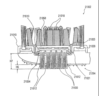
12070 span less than 25% of the total distance between the proximal and distal
pods 12010
and 12020, respectively.
[114] In addition, the configuration shown in Figures 19 and 20 includes a
unitary
assembly 12500 that includes proximal pod 12010, distal pod 12020, bridge
supports 12060
18
CA 02833839 2013-11-20
62301-2992D1
and 12070 and central pods 12032 and 12034, which can be molded as a single
unit from the
same material. The unitary assembly 12500 may be made from an elastomeric
material, such
as a soft thermoplastic elastomer (TPE). Again, other rubber-like materials
may be used,
such as other thermoplastics (e.g., polypropylene), a thermoplastic urethane,
a thermoplastic
plastomer, or any combination thereof. The proximal and distal pods can be
attached to
protrusions (not shown) extending from the underlying head 12002, thereby
providing
sufficient support and strength to the proximal and distal pods.
[1151 Alternatively, these features could be formed as differentiated
features, such as
the proximal and distal pods being formed as unitary features along with the
frame of the
head, such as from a unitary plastic mold, and the central pods being formed
separately from
the Proximal and distal pods. When formed as differentiated features, the
proximal and distal
pods could be formed from the same or different materials than the frame, the
bridge supports
and/or the central pods. =For instance, the bridge supports and central pods
could be made
from a fust thermoplastic material, and the proximal and distal pods could be
formed
separately from a second thermoplastic material, such as polypropylene_ In
such a
configuration, the bridge supports and the central pods could be made as a
unitary
construction that is welded or adhered to the proximal and distal pods.
Further, the bridge
supports, the central pods, and the proximal and distal pods could be formed
as a unitary
member that is attached to the frame. For instance, the central pods, the
proximal and distal
pods, and the bridge supports could be molded as a unitary cleaning elements
assembly. The
cleaning elements could be attached to the pods and pod components thereafter,
such as via
= AFT techniques. Optionally, an elastic membrane, such as membrane 13070
and 13670
shown in Figures 21A and 21B, could be formed around the proximal and distal
pods, the
central pods, and the bridge supports.
0.1.61 As discussed with regard to the embodiment shown in Figures 7 and 8,
the
cleaning elements 12218 mounted on the central pods can be adapted to engage a
user's teeth,
gums and other surfaces in a various ways that take advantage of their
flexible support
configuration. For instance, as shown in Figure 19, the cleaning elements
provided on the
central pods can include forward elements 12090 angled toward the tip end of
the head, and
rearward elements 12092 angled toward the handle end. The location and
orientation of these
forward and rearward elements can increase the likelihood such elements will
initially engage
a surface to be cleaned prior to other cleaning elements on the respective
pod, thereby
encouraging the respective pod to flex as the remaining cleaning elements
thereon engage the
surface.
19
CA 02833839 2013-11-20
62301-2992D1
11171 As further shown in Figure 19, cleaning elements 12218 may include
upstanding walls 12094, which may be elastomeric or bristle-based as discussed
above. The
upstanding walls can provide beneficial wiping and polishing of teeth in
addition to cleaning
benefits. Cleaning elements 12218 may further include a central columnar
cleaning element
12270, which rnay include one or more bristles for penetrating oral surfaces.
The columnar
cleaning elements may extend beyond other cleaning elements proxiMate thereto
on the same
pod, and they may have a generally pointed tip. As such, central cleaning
element 12270 can
effectively penetrate and engage oral surfaces and gaps between surfaces.
1118] The tips or terminal ends of cleaning elements 12218 may be tapered such
that
the suspended pods are respectively encouraged toward their adjacent proximal
or distal pod
12020 and 12010, respectively, while engaging surfaces to be cleaned. Thus,
during use,
cleaning elements extending from central pod 12032 may generally be biased
toward
engagement with cleaning elements extending from proximal pod 12010, whereas
cleaning
elements extending from central pod 12034 may generally be biased toward
engagement with
cleaning elements extending from distal pod 12020. This bias can cooperate
with movement
of the pods imparted via engagement of angled cleaning elements with cleaning
surfaces
when the device is being moved. Increasing movement and the flexing of the
suspended
central pods 12032 and 12034 further enhances the cleaning effectiveness of
the oral care
implement.
[119] Referring now to Figure 21A, a toothbrush 13000 is shown that is similar
to
the embodiment illustrated in Figures 19 and 20 and generally has the same the
aspects and
features, except as pertaining to its central pod and the configuration of
cleaning elements
13218 and its lack of a soft tissue cleaner. Toothbrush 13000 includes a
handle 8103 and a
head 13002 having a combination of fixed and suspended cleaning elements. Head
13002
includes a frame 13004, proximal and distal pods 13010 and 13020, and a single
central pod
13050 suspended between the proximal and distal pods. The handle 8103, head
13002 and
proximal and distal pods 13010 and 13020 may be formed as a unitary
construction from a
thermoplastic, such as polypropylene. Further, similar to toothbrush 12000
shown in Figs. 19
and 20, toothbrush 13000 could include a unitary cleaning elements assembly
13500 that
includes proximal pod 13010, distal pod 13020, central pods 13032 and 13034,
bridge
supports 13060, and (optionally) membrane 13070.
[120] As with unitary cleaning elements assembly 12500, unitary cleaning
elements
assembly 13500 can be formed from proximal pod 13010, distal pod 13020,
central pod
13050 and bridge supports 13060, which can be molded as a single unit from the
same
CA 02833839 2013-11-20
62301-2992D1
material. Bridge supports 13060 can be formed from portions of membrane 13070
disposed
between the central pod and an adjacent pod. The membrane can be formed from a
thermoplastic elastomer that is molded about the proximal and distal pods and
the central pod
to form a unitary assembly. Optionally, bridge supports 13060 could also
include reinforcing
bridge supports (not shown in Figure 21A), such as bridge supports 12060 shown
in Figures
19 and 20, as well as the bridge-supports that are formed from portions of
membrane 13070.
The reinforcing bridge supports can be formed from a more robust material than
the
membrane, such as from polypropylene. The portions of membrane 13070 can be
molded
around the reinforcing bridge supports to partially or completely encapsulate
them within the
membrane material. In such a configuration, the reinforcing bridge supports
can be fairly
rigid supports that reinforce the flexible connection provided by the
membrane. The
reinforcing bridge supports (e.g., bridge supports 12060 of Figures 19 and 20)
can be formed
via injection molding along with the central pod and the proximal and distal
pods as a unitary
assembly with the pods, and the membrane 13070 can be formed thereafter.
11211 Single central pod 13050 has an elastomeric section 13055 disposed in a
middle portion of the central pod. The elastomeric section is preferably made
from a resilient
material, such as a soft thermoplastic elastomer (TPE), while the central pod
is preferably
made from a more rigid material, such as polypropylene. The central pod 13050
is held in
place by a molded TPE membrane 13070 that connects with the proximal and
distal pods
13010 and 13020 to form bridge supports 13060. The membrane 13070 may form a
loop that
encompasses the pair of fixed proximal and distal pods 13010 and 13020 and
attaches to
opposing sides of central pod 13050. Grooves (not shown) in side portions of
the proximal
and distal pods, as well as the central pod, may receive membrane 13070. In
addition,
membrane 13070 may be attached to the pods via an adhesive and/or a melt bond.
[122] Membrane 13070 allows the central pod 13050 to move toward frame 13004
when sufficient force is applied during a cleaning operation. When such force
is applied to
the central pod, opposite halves 13051 and 13053 of the central pod will also
flex about the
elastomeric section 13055. As a result, the two sets of cleaning elements
13218 extending
from either end of the central pod 13050 can rotate toward one another. The
central pod
13050 can ilex back to its original position when the force on the central pod
moving it
toward the head 13002 diminishes.
[1231 Cleaning elements 13218 extending from central pod 13050 are generally
centrally-tapered, which is generally an opposite orientation to the
configuration of cleaning
elements shown in Figures 10 and 11 and Figures 19 and 20. The central taper
encourages
21
CA 02833839 2013-11-20
62301-2992D1
cleaning elements 13218 to penetrate interproximal spaces of the user's teeth
while applying
moderate force to toothbrush 13000 against their teeth. When the user applies
more
excessive force to=the toothbrush, central pod 13050 moves into contact with
frame 13004
and causes the central pod to bend about elastomeric section 13055 and further
engage the
interproximal space to which the cleaning elements are applied.
[124] Fig. 21B shows an optional unitary cleaning elements assembly 13600 that
could be used with toothbrush 13000 instead of unitary cleaning elements
assembly 13500.
Cleaning elements unitary assembly 13600 generally includes the aspects and
preferences of
cleaning elements 13500, except with respect to reinforcement connectors 13671
and as
discussed hereafter. As shown, unitary cleaning elements assembly 13600
includes proximal
pod 13610, distal pod 13620, bridge supports 13660, central pod 13650, and
membrane
= 13670 (shown in broken line). Cleaning elements assembly 13600 differs
from unitary
assembly 13500 in that its bridge supports 13660 include reinforcement
connectors 13671
having an offset configuration, as well as portions 13673 of membrane 13670
that are
disposed between adjacent pods.
[125] As shown in Figure 21B, reinforcement connectors 13671 connect central
pod
13650 to adjacent pods 13610 and 13620 in an offset configuration. In such a
configuration,
the connection points 13675 between the movable central pod and each
reinforcement
connector is laterally offset with respect to the toothbrush head from
corresponding
connection points 13677, which are disposed between the fixed pods 13610 and
13620 and
the reinforcement connectors. As shown in the configuration of Figure 21B1
connection
points 13675 and 13677 can have greater cross-sections than the intermediate
or neck portion
13679 of each connector, which can encourage the reinforcement connectors to
flex primarily
at their neck portions during use. An offset reinforcement connector can
provide a sturdy
connection between the movable central pod and the fixed pods while providing
flexibility in
the desired up and down directions relative to the head platform or frame.
This can be due, at
least in part, by the neck portions 13679 acting as torsional living hinges
that are twisted as
the movable central pod moves toward and away from the head platform. Lateral
movement
of the central pod toward and away from the fixed pods can be limited via
interference
between the relatively thick connection points 13677, 13679 and the adjacent
pod. A desired
amount of connector flexibility can be provided based on selected thickness of
the neck and
the type of connector material. In one configuration, the offset reinforcement
connector can
be made from a relatively stiff, but flexible, material, such as polypropylene
or high density
polyethylene. Further, the offset reinforcement connectors 13671 can be made
from the same
22
CA 02833839 2013-11-20
62301-2992D1
material as the proximal pod 13610, distal pod 13620, bridge supports 13660
and central pod
13650, which can be molded as a single unit.
[126] Referring now to Figures 22A and 22B, a toothbrush 13010 is shown that
is
similar to the embodiment illustrated in Figure 2IA and generally has the same
the aspects
and features as toothbrush 13000, except as pertaining to its frame. As shown,
frame 13007
includes a resilient hinge element 13080 located in a central portion of the
frame and
traversing its width. The hinge element may be formed from a TPE or other
resilient material
that is more flexible than other portions of the frame. The hinge element may
also include a
reduced thickness region of the frame about which a TPE or other resilient
material is
disposed.. For instance, a proximal portion 13082 of the frame and a distal
portion 13084 of
the frame may be formed from a relatively rigid material, such as a
polypropylene material,
and may include a thin neck region (not shown) disposed therebetween. The neck
region
may permit the proximal and distal portion of the frame to rotate with respect
to each other.
A resilient material 13081 may surround the neck to dampen rotation about the
neck. The
resilient material may be adhered to the frame via an adhesive bond, a melt
bond or other
attachment mechanism, such as a compression fit about the neck.
[127] Hinge element 13080 permits proximal and distal portions 13082 and 13084
respectively of frame 13004 to rotate with respect to one another during use.
Thus, head
13010 can generally curl or bend around a surface to be cleaned, such as a
user's tooth as
illustrated in Figure 228. In addition, hinge element 13080 can simply improve
the overall
flexibility of the head for adapting to a variety of cleaning-features,
orientations of use, and
applied forces. For instance, as shown in Figure 22B, hinge element 13080 can
permit frame
13007 to flex like a bow. In another example (not shown), hinge element 13080
can permit
the tip portion of the head to be flexed rearward, which will encourage
central pod 13050 to
move away from the frame as the bridge supports are stretched taut.
[128] Referring now to Figures 23A and 23B, an oral care implement 13020 is
shown that is similar to the embodiment illustrated in Figure 21A and
generally has the same
the aspects and features as toothbrush 13000, except as pertaining to its
central pod, the
arrangement of cleaning elements 13218, and the existence of a soft tissue
cleaner 13280
disposed on a rear side of its head that is opposite to the front side. The
soft tissue cleaner
13280 is generally the same as soft tissue cleaners 10280 and 12280 of Figures
10-13 and 19-
20 respectively. However, various soft tissue cleaner configurations may be
used, such as the
soft tissue cleaners of Figures 14-18. Toothbrush 13020 includes a central pod
13058 that is
substantially unitary and lacks elastomeric section 13055 of toothbrush 13000.
Thus, the
23
CA 02833839 2013-11-20
62301-2992D1
central pod can provide relatively firm engagement of oral features to be
cleaned via the
larger rigid central pod, while retaining benefits provided via its suspended
configuration. As
such, central pod can adapt to the cleaning forces applied to the head by
moving fore, aft,
sideways and/or downward with respect to the frame. However, its relatively
large, rigid size
can provide uniform orientation to a large number of cleaning members 13218
attached
thereto.
[1291 Cleaning elements 13218 extending from the central pod are similar to
the
cleaning elements 12218 of toothbrush 12000 and generally include the same
configuration,
aspects and features as cleaning elements 12218 shown in Figure 19. However,
as central
pod 13058 is a single pod that spans about the same distance as central pods
12032 and
12034 of toothbrush 12000 in Figure 19, central pod 13058 includes additional
cleaning
. elements in its central region. As shown in Figure 23A, a central columnar
cleaning element
13096 is located at a central portion of the central pod, which is similar to
columnar cleaning
elements 12270 of toothbrush 12000. Columnar cleaning element 13096 cooperates
with
columnar cleaning elements 12270 to effectively penetrate and engage oral
surfaces and gaps
between surfaces and to transmit downward force to the central pod when
excessive cleaning
force is applied to the cleaning elements. In addition, several radial
cleaning elements 13098
extend from the central columnar cleaning element 13096 in a generally spoke-
like
configuration at a central region of the central pod. Radial cleaning elements
engage features
to be cleaned throughout a central portion of the pod, which provide a
perimeter structure at
side portions of the central pod. The perimeter structure enhances engagement
of oral
features to be cleaned and can assist with retaining dentifrice within the
cleaning elements of
the central pod during use.
[1301 Referring now to Figures 24A and 24B, a toothbrush 14000 is shown that
is
similar to the embodiment illustrated in Figure 21A and comprises a handle 8
103 and a head
14002 having a combination of fixed and suspended cleaning elements. Head
14002 includes
a frame 14004, proximal and distal pods 14010 and 14020 having cleaning
elements 14018,
and a single central pod 14050 suspended between the proximal and distal pods.
The handle
8 103, head 14002 and proximal and distal pods 14010 and 14020 may be formed
as a unitary
construction from a thermoplastic, such as polypropylene. A soft tissue
cleaner 14280 is
generally the same as soft tissue cleaners 10280 and 12280 of Figures 10-13
and 19-20
respectively. However, various soft tissue cleaner configurations may be used,
such as the
soft tissue cleaners of Figures 14-18.
24
CA 02833839 2013-11-20
62301-2992D1
=
[131] Central pod 14050 has an elastomeric section 14055 disposed in a middle
portion of the central pod, or more particularly between a pair of pod
segments. The
elastomeric section is preferably made from a resilient material, such as a
soft thermoplastic
elastomer (TPE), while the central pod is preferably made from more rigid
material, such as
polypropylene. The central pod 14050 is held in place by a molded TPE membrane
14070
that connects with the proximal and distal pods 1401.0 and 14020 to form
bridge supports
14060. The membrane 14070 may fon-n a loop that encompasses the pair of fixed
proximal
and distal pods 14010 and 14020 and attaches to opposing sides of central pod
14050.
Grooves (not shown) in side portions of the proximal and distal pods, as well
as the central
pod, may receive membrane 14070. In addition, membrane 14070 may be attached
to the
pods via an adhesive and/or a melt bond, for example.
[132] The cleaning elements 14218 on the central pod 14050 are similar to the
configuration of the cleaning elements shown in Figures 19 and 20, with the
exception of a
plurality of central, flexible cleaning elements 14270 extending from the
frame 14004 and
protruding through one or more openings (not shown) in the central pod 14050.
Cleaning
element 14270 further comprises massaging and/or polishing elements 14272 on
its upper
surface. While two cleaning elements 14270 are shown, it will be appreciated
that only one,
or more than two cleaning elements 14270 may be used as desired. Cleaning
element 14270
may be attached to the frame 14004, or extend through the frame 14004 from the
soft tissue
cleaner 14280 on the opposite side of the head 14002. If the latter, the
cleaning element
14270 may be molded simultaneously with the soft tissue cleaner 14280. In
either case, a
unitary structure defined by the membrane 14070 carrying pods 14010, 14020 and
14050,
could be assembled to the base 14004 over the cleaning element(s) 14270. Other
methods of
construction are contemplated.
[1331 Membrane 14070 allows the central pod 14050 and cleaning elements 14218
to move toward frame 14004, guided by the cleaning elements 14270, when
sufficient force
is applied during a cleaning operation. Such movement provides additional
functionality not
described before. One such functionality is a tooth polisher in the middle of
the head that is
surrounded by fixed and movable cleaning elements 14018, 14218 respectively.
In addition,
the cleaning element 14270 includes massaging and/or polishing elements 14272
that are at a
fixed height relative to the head 14004, yet are surrounded by cleaning
elements 14218 that
recede toward the head 14004 under brushing pressure, enabling the cleaning
elements 14272
to be more efficacious during brushing.
CA 02833839 2013-11-20
62301-2992D1
11341 When brushing pressure force is applied to the central pod 14050,
segments
14051 and 14053 of the central pod 14050, as well as the cleaning elements
14270, will flex
about the elastomeric section 14055. As a result, the cleaning elements 14218
extending
from either end of the central pod 14050, as well as the cleaning elements
14270, can rotate
toward one another. The central pod 14050 can flex back to its original
position when the
force on the central pod moving it toward the head 14002 diminishes.
[135] Referring now to Figures 25A-25E, a toothbrush 15000A-C is shown that is
similar to the embodiment illustrated in Figures 23A and 23B and comprises a
handle 8103
and a head 15002 having a combination of fixed and suspended cleaning
elements. Head
15002 includes a frame 15004, proximal and distal pods 15010 and 15020 having
cleaning
elements 15018, and a central pod 15050 defined by pod segments 15051-15054
(embodiments of Figures 25A through 25D) or pod segments 15055 through 15058
(embodiment of Figure 25E) suspended between the proximal and distal pods. The
handle
8103, head 15002 and proximal and distal pods 15010 and 15020 may be formed as
a unitary
construction from a thermoplastic, such as polypropylene.
[136] The central pod segments 15051-15058 are held in place by a molded TPE
membrane 15070 that cormects with the proximal and distal pods 15010 and 15020
to form
bridge supports 15060. The membrane 15070 may form a loop that encompasses the
pair of
fixed proximal and distal pods 15010 and 15020 and central pod segments 15051-
15058,
which segments may be separated by a flexible gap 15062 along the longitudinal
axis
(embodiment of Figures 25A and 25B) or lateral axis (embodiment of Figures 25C
and 25D)
of the head 15002. Alternatively, segments 15055-15058 of the embodiment of
Figure 25E
may be separated by a flexible gap 15062 along both the longitudinal and
lateral axes of the
head. Grooves (not shown) in the pods may receive membrane 15070. In addition,
membrane 15070 may be attached to the pods via an adhesive and/or a melt bond,
for
example.
[137] The cleaning elements 15218 on the central pod segments are similar to
the
configuration of the cleaning elements shown in Figures 23A and 23B, with the
exception of
a central cleaning element 15270 having polishing ridges 15272 along its upper
surface that
protrudes through an opening (not shown) in the membrane 15070. Such cleaning
element
15270 functions in a similar manner as cleaning element 14270 of Figures 24A
and 24B,
relative to the membrane 15070 and the central pod segments 15051, 15053 of
Figures 25A
and 25B. However, because the central pod segments 15051, 15053 are separated
along the
longitudinal axis of the head 15002 by a gap 15062, such segments 15051, 15053
will tend to
26
CA 02833839 2013-11-20
62301-2992D1
rotate away from the protruding cleaning element 15270, or rotate around the
cleaning
element 15270, under brushing pressure, thereby simulating the movement of a
bird's wings,
resulting in increased efficacy and interproximal penetration. A similar
movement is
experienced along the transverse axis with segments 15052, 15054 of Figures
24C and 24D,
and an even more extensive movement is experienced along the longitudinal and
transverse
axes with segments 15055-15058 of Figure 25E. Thus, cleaning element 15270
provides a
central pivot around which pod segments 15051-15058 can move.
[138] Cleaning element 15270 may be attached to the frame 15004, or extend
through the frame 15004 from a soft tissue cleaner (not shown) on the opposite
side of the
head 15002. If the latter, the cleaning element 15270 may be molded
simultaneously with the
soft tissue cleaner. In either case, a unitary structure defined by the
membrane 15070
carrying pods 15010, 15020 and central pod 15050 segments 15051-15058, could
be
assembled to the base 15004 over the cleaning element 15270. Other methods of
construction are contemplated.
[139] Referring now to Figures 26 and 27, a toothbrush 16000 comprises a
handle
8103 and a head 16002 having a combination of fixed and suspended cleaning
elements.
Head 16002 includes a frame 16004, proximal and distal pods 16010 and 16020
having
cleaning elements 16018, and a central pod 16050 defined by pod segments 16051
and 16053
suspended between the proximal and distal pods. The handle 8103, head 16002
and proximal
and distal pods 16010 and 16020 may be formed as a unitary construction from a
thermoplastic, such as polypropylene.
[140] The central pod segments 16051 and 16053 may be separated by a bridge
16052 that is preferably flexible and formed from the same material as a
molded TPE
membrane 16070 that connects with the proximal and distal pods 16010 and 16020
to form
bridge supports 16060. The membrane 16070 may form a loop that encompasses the
pair of
fixed proximal and distal pods 16010 and 16020 and central pod 16050 including
segments
1605 1 and 16053, which segments may be separated by a flexible gap 16062
along the
lateral axis of the head 16002 and/or along the longitudinal axis as shown in
other
embodiments (see, for example, FIGS. 25A- 25E). Grooves (not shown) in the
pods rnay
receive membrane 16070. In addition, membrane 16070 may be attached to the
pods via an
adhesive and/or a melt bond, for example.
[1411 Proximal and distal pods 16010 and 16020 may be integral with the head
frame 16004, such that the membrane extends around the central portion of such
pods, or the
pods may terminate at the edge of the membrane 16070 (see the bottom of pod
16050 in
27
CA 02833839 2013-11-20
62301-2992D1
FIGURE 27) and be attachable to the head frame 16004 by ultrasonic welding,
adhesive or
the like. Accordingly, membrane 16070 may serve as an outer frame to a plate
of cleaning
elements included on pods 16010, 16020 and 16050, which plate may be
attachable as a
single unit to the head frame 16004. Thus, the pods 16010, 16020 and 16050 may
be
assembled and manipulated as a single unit and attachable to the head frame
16004 as a
single unit at the proximal and distal ends of the head frame 16004.
[1421 FIGURE 27 illustrates the construction of a portion of pod 16050, and
more
specifically a portion of pod 16051, wherein the bottoms 16019 of cleaning
elements 1 601 8
are melted to form a mat 16021, which mat 16021 is captured between a pod
housing 16053
and floor 16054. The mat 16021 prevents the cleaning elements 16018 from
passing through
the tuft holes in the pod housing 16053. The floor 16054, for example, could
be adhered or
welded to the housing 16053, with the floor 16054 being at least partially
surrounded by the
membrane 16070. Thus, the cleaning elements 16018 in this embodiment are
captured and
secured within the pod housing 16053 and floor 16054 in a manner known as
anchor-free
tufting (AFT), but such cleaning elements are not rigidly and securely fixed
to any particular
support structure in the manner of a stapled tuft secured within a tuft hole.
11431 The cleaning elements 16018 on the proximal and distal pods 16010 and
16020 may be supported using an AFT process as described above, wherein they
would be
captured between the respective pod housing and the head frame, or they may be
anchored to
the pods 16010, 16020 if such pods constitute integral extensions of the head
frame 16004. If
they are provided using an AFT process, the connection between the pod housing
and the
head frame would constitute an edge connection, with the pod housing being
welded, for
example, to the head frame along the periphery of the pod housing to allow for
the mat of
melted bristle ends to reside between the pod housing and the head frame.
[1441 When brushing with the toothbrush of, for example, FIGS. 22A-22B, that
has
a toothbrush head that is comprised of several areas with affixed cleaning
elements (proximal
and distal ends) interconnected with a flexible, central rubber-like field,
the central area can
bottom and touch the head frame below in an uncontrollable fashion (see FIGURE
22B). As
a result there may be a clanking noise, a significant "slippage/stretching" of
the central
portion of the flexible field with an imbedded block(s) of cleaning elements
that may cause a
damage either to the structure or to the user. By incorporating supports that
protrude upwards
from the brush head, the flexible field's movements can be controlled with an
intent to enable
the flexible field to move in a particular fashion relative to the brush head.
28
CA 02833839 2013-11-20
= 62301-2992D1
[145] FIGS. 26 arid 27 illustrate one example of a single, central protrusion
16270
= extending from a soft tissue cleaner 16280 on the back of the head 16002
to a depression or
notch 16055 provided in the floor 16054 of the tuft block 16050. Such
protrusion 16270 is
preferably formed or unitarily molded together with the soft tissue cleaner
16280 of a flexible
material, although it does not have to be, and provides a pivot point for pod
16050. This
enables pod 16050 to move in a controlled fashion relative to the head frame
16004.
Depending on the flexibility of the protrusion 16270, pod 16050 may also be
capable of
normal movement or movement toward the head frame 16004 (again, see FIGURE 22B
for
example). Alternatively, the protrusion 16270 may be rigid and extend from the
head frame
16004 to provide a rigid pivot point that resists normal movement of the pod
16050 toward
the head frame 16004. Or course, while a single, central protrusion 16270 is
illustrated in
FIGS. 26 and 27, the number and type of protrusions or supports may vary as
shown in, but
not limited to, FIGURE 28 (multiple supports 17270 and 17271 extending between
head
frame 17004 and central pod 17050) and FIGURE 29 (transverse bar support 18270
extending from the head frame 18004 along the transverse axis of the central
pod 18050 of
toothbrush 18000, making line contact with the central pod 18050). Each of the
embodiments of FIGS. 26-29 enables unique movement of the flexible pod
relative to the
head frame, with the structure illustrated in FIGS. 26-27 enabling at least a
360 degree pivot,
the structure illustrated in FIGURE 28 enabling a more restrictive pivoting
movement, and
the structure illustrated in FIGURE 29 enabling a rocking movement over
protrusion 18270.
= [146] Figure 33 schematically illustrates a head 20112 of an oral care
implement
20110, which may be placed on the handle of a conventional toothbrush, such as
handle
19014 of conventional toothbrush 19010 shown in Figure 30. Head 20112
generally includes
a head platform 20118 having a first face 20119, a second face 20121, a first
set of cleaning
elements 20116 and a second set of cleaning elements 20122_ The first set of
cleaning
elements extends outwardly from the first face and the second set of cleaning
elements
extends outwardly from the second face.
11471 In the configuration shown in Figure 32, head platform 20118 includes
only
two faces from which cleaning elements extend. It is understood that the head
platform could
include more than two faces from which cleaning elements extend. Further, it
is understood
that the faces having cleaning elements could be arranged in various
configurations that may
or may not be opposite to another face. For instance, another configuration of
head 20112
could include a head platform with three faces from which cleaning elements
extend that are
arranged in a generally triangular arrangement. However, as discussed further
below, the
29
CA 02833839 2013-11-20
62301-2992D1
configuration of head platform 20118 with opposite faces, a relatively thin
platform height
HP, and a relatively thin overall height H3 provides various advantages during
use.
[1481 Cleaning elements 20116 and 20122 as shown may extend perpendicularly
from their respective faces 20119 and 20121. Further, the cleaning elements
may extend in
opposite directions from each other. However, it is understood that the
cleaning elements
may be configured in other orientations. For example, the cleaning elements
can be angled
with respect to their face and with respect to each other.
[149] Cleaning elements 20116 and 20122 may include a variety of oral cleaning
elements, such as tooth cleaning elements, which can be used for wiping,
cleaning and
massaging the user's teeth and gums, and soft tissue cleaning elements, which
can be used for
scrubbing, scraping and massaging the user's tongue, inside of cheeks, etc.
Any suitable
form of oral cleaning elements may be used. However, as discussed further
below, it is
preferable to include filament bristles with both the tooth cleaning elements
and the soft
tissue cleaning elements. The tenn "oral cleaning elements" is used in a
generic sense and
generally refers to filament bristles, elastomeric fingers or walls that have
any desirable
shape, tissue engaging projections such ridges and nubs, etc. As used herein,
a "nub" is
generally meant to include a column-like protrusion (without limitation to the
cross-sectional
shape of the protrusion), which is upstanding from a base surface.
[150] Preferably, cleaning elements 20116 and 20122 include filament bristles,
either alone or in combination with other types of oral cleaning elements.
Cleaning elements
20116 are generally tooth cleaning elements, which may include elastomeric
fingers or walls
along with filament bristles. As such, cleaning elements 20116 have a height
114 from 10
mm to 13 min, which provide sufficient =length and flexibility for engaging
gaps and crevices
between the user's teeth and between their teeth and gums and for brushing or
wiping away
particles engaged by the cleaning elements.
[151] Cleaning elements 20122 are generally soft tissue cleaning elements,
which
may include tissue engaging projections, such as ridges and nubs, and/or
elastomeric fingers
or walls along with relatively short filament bristles. Such tissue engaging
elements can help
reduce a major source of bad breath and improve hygiene. Cleaning elements
20122 have a
height H5 from 1 mm to 6 mm and preferably from 1.5 mm to 4 mm.
[1521 Filament bristles having a height in the range of 1 mm to 6 mm and
preferably
in the range of 1.5 mm to 4 mm are relatively short in comparison to their
column width,
= which preferably is in the range of 0.06 to 0.18 mm +/- to 0.02 mm for
individual filaments
and in the range of 1 mm to 2 mm +/- 0.2 mm for individual bundles of
bristles. As such,
CA 02833839 2013-11-20
62301-2992D1
filament bristles of cleaning elements 20122 have a relatively high column
strength in
comparison with filament bristles of tooth cleaning elements 20116, which are
longer and
more flexible than tissue cleaning elements 20122. Due to their thin diameter
and their high
column strength, the relatively short tissue cleaning elements and, in
particular, the relatively
short filament bristles are able to penetrate very well into the user's soft
oral tissues.
[153] In the configuration shown in Figure 32, oral cleaning elements 20122
are able
to engage soft tissues within the user's mouth, such as the inside of their
cheeks, while the
user simultaneously cleans their teeth. Thus, more effective oral cleaning is
provided by oral
cleaning implement 20110 than conventional toothbrush 19010 or conventional
combination
toothbrush/tongue cleaner 19030. This is true even though combination device
19030
includes soft elastomeric tongue cleaning projections 19020, which can
penetrate a user's soft
oral tissues, but do not penetrate as well as relatively short, thin filament
bristles 20122, and
which fail to provide the brushing action of filament bristles 20122.
[154] In general, soft tissue cleaning elements 20122 enable the removal of
microflora and other debris from the tongue and other soft tissue surfaces
within the mouth.
The tongue, in particular, is prone to develop bacterial coatings that are
known to harbor
organisms and debris that can contribute to bad breath. These microfloras can
be found in the
recesses between the papillae on most of the tongue's upper surface as well as
along other
soft tissue surfaces in the user's mouth. When engaged or otherwise pulled
against a tongue
surface, for example, the filament bristles of tissue cleaning elements 20122
can provide for
gentle engagement with the soft tissue while reaching downward into the
recesses of adjacent
papillae of the tongue and while providing a brushing action within the
recesses.
[155] = The columnar filament construction of the bristles also enables the
soft tissue
cleaning elements to follow the natural contours of the oral tissue surfaces,
such as the
tongue, cheeks, lips, and gums of a user. In addition, the filament bristles
are able to flex as
needed to traverse and clean the soft tissue surfaces in the mouth along they
are moved. The
flexibility of the filament bristle tissue cleaning elements, their small
diameter, and their
relatively high column strength allow them to effectively penetrate soft oral
tissues and to
engage and brush out microflora and other debris much better than other types
of tissue
cleaning elements.
[156] Conventional combination toothbrush/tongue cleaner devices, such as
device
19030 shown in Figure 31, have failed to provide filament bristles in tongue
cleaner 19020.
This is because conventional techniques for affixing filament bristles to a
toothbrush, such as
the conventional method of stapling folded bristle bundles into a head, would
require a much
31
CA 02833839 2013-11-20
62301-2992D1
thicker head than would be comfortable for most adult users in order to
accommodate bristles
on opposite sides of the toothbrush. As such, conventional toothbrush/tongue
cleaner devices
include a pad of elastomeric tongue cleaning elements glued to the back of the
toothbrush
head, or a plurality of hard projections molded on the back of the toothbrush
head. However,
such conventional devices fail to provide filament bristle soft tissue
cleaning elements 20122 =
along with filament bristle tooth cleaning elements 20116 on the head of the
same device
while having a head thickness small enough for comfortable use by an adult.
[1571 To furtherenhance the effectiveness of oral care implement device 20110,
device 20110 can optionally include a vibratory device (not shown) to vibrate
the oral care
implement or a portion thereof, such as the head 20112 or a portion thereof.
The vibration-
producing device can be used to vibrate tooth cleaning elements 20116 and/or
soft tissue
cleaning elements 20122.
[158] A wide variety of vibratory devices can be used to produce vibrations
over a
wide range of frequencies to meet the needs of a particular application.
Various types of
vibratory devices are commercially available, such as transducers. One example
of a
vibratory device provides frequencies in the range of about 100 to 350 kHz.
The vibration
frequencies may be of different wavefornis, including sinusoid, square, saw
tooth and the
like. Nevertheless, other values and waveforms are possible. A vibratory
device may be
located in head of the toothbrush or neck thereof. When activated, vibratory
device is
powered by battery (and controlled by electronics on circuit board or
switching system) so as
to induce vibrations in head of the toothbrush and thereby enhances teeth-
cleaning action
imparted by the tooth cleaning elements.
[159] In alternate embodiments, a vibratory device may include a micro motor
attached to a shaft, with the shaft coupled to an eccentric rotating about an
axis parallel to the
longitudinal axis of the toothbrush. In still other embodiments, a vibratory-
producing device
includes an eccentric that is driven by a micro motor in a translatory manner.
(160] A switch, such as a button, toggle switch, rotating dial, or the like,
can be
provided for activating the vibratory device. A vibratory device often has a
power source,
such as a battery. Activating the switch can cause the vibration-producing
device to operate
for a user-defined interval (e.g., during the time that a button is depressed
or a switch is in an
engaged position), or alternatively can activate a timing circuit that causes
the vibratory
device to operate for a predetermined interval. If a timing circuit is used,
the associated
interval either may be preset or may be adjustable, e.g., by a user-activated
rotating dial.
32
CA 02833839 2013-11-20
62301-2992D1
0611 Figs. 33-35 illustrate a method 20210 for forming an oral cleaning
device,
such as oral care implement 20110, having a pair of faces that include
filament bristles (i.e.,
tufted faces), which permits the head to have an overall thickness of 20 mm or
less. As
shown in Figs. 33 and 34, method 20210 can be practiced via anchor-free
tufting (AFT)
techniques. Accordingly, head 20112 includes a first carrier plate 20128 to
which tooth
cleaning elements 20116 are affixed via AFT processing and a second carrier
plate 20132 to
which oral cleaning elements 20122 are affixed via AFT processing. The carrier
plates have
a plurality of cutouts (not shown) through which clusters of bristle filaments
20116, and
optionally elastomeric cleaning elements 20116, are guided. The rear ends of
the bristle
filaments are melted to affix them to their respective carrier plate. The
melted portions form
a base 20131 that adheres to the carrier plate and bonds the bristle bundles
to each other. If
elastomeric cleaning elements are also provided, they can be melted along with
the bristles or
glued to the carrier plate.
[162] The carrier plates 20128 and 20132 are relatively thin (e.g., 1 min or
less) and
are received into corresponding recesses 20124 and 20126 fonned in the faces
20119 and
20121 of the head platform 20112. The carrier plates may be affixed to the
head platform via
appropriate methods such as ultrasonic welding, laser welding, hot air welding
gluing, a snap-
fit connection in combination with overmolding, or any other plastic joining
technique.
Other suitable plastic joining techniques will become readily apparent to
those skilled in the
art, given the benefit of this disclosure. Preferably, carrier plates 20128
and 20132 are
affixed via ultrasonic welding to membrane 20134 of the head platform, which
provides a
non-visible, high strength bond to the head platform at a relatively low
manufacturing cost.
[163] As illustrated in Figure 35, a method 20210 for forming such an oral
cleaning
device can include the step 20212 of molding an oral care implement head
platform 20118
having a first cavity 20124 on a first side and second cavity 20126 on a
second side. It can
further include the steps 20214 of guiding tooth cleaning elements 20116
including bristles
into cutouts of first carrier plate 20128 via AFT processing and the step
20216 of guiding soft
tissue cleaning elements 20122 including bristles into cutouts of second
carrier plate 20132
via AFT processing. The method also includes the step 20218 of inserting the
first carrier
plate 20128 into the first cavity 20124 and affixing it to head platform 20118
and the step
20220 of inserting the second carrier plate 20132 into the second cavity 20126
and affixing it
to head platform 20118.
[164] As noted above, the carrier plates are preferably affixed via
ultrasonically
welding them to the head platform, such as welding them to platform 134 of the
head
33
CA 02833839 2013-11-20
62301-2992D1
platform. However, they may be affixed via other methods, such as gluing them
to the head
platform or snap fitting them into the head platform and ovennolding another
material around
portions of the head platform and the carrier plates. It is understood that
the steps of method
20210 may be performed in various orders and that many steps may be performed
simultaneously. For instance, steps 20214 and 20216 can be sequentially in any
order or can
be performed simultaneously.
[1651 Referring now to Figs. 36 and 37, a head portion 20312 is shown of an
oral
care implement 20310, which generally includes the same aspects and features
as oral care
implement 20110 and head portion 20112 except as discussed hereafter. Like
numbers in
Figs. 36 and 37 refer to like features of Figs. 33 and 34. As shown in Figs.
36 and 37, head
platform 20318 includes a support rib 20336 disposed between first cavity
20324 and second
cavity 203261 Gaps 20338 and 20340 are formed on each side of support rib
20336, which
are openings connecting first cavity 20324 and second cavity 20326. Each of
the canier
plates 20328 and 20332 include a rim 20333 and 20335 along the portion that is
received into
its corresponding cavity 20324 and 20326 of the head platform. Each rim
includes a pair of
recesses 20342 and 20344 or 20346 and 20348, which engage support rib 20336 of
the head
platform when attached thereto.
[166] The configuration of Figs. 36 and 37 permit opposing carrier plates
20328 and
20332 to be attached directly to each other. Such a configuration permits head
platform
20318 to be even thinner than head platform 20118. Having a thinner head
platform provides
the advantage of permitting tooth cleaning elements 20316 and/or soft tissue
cleaning
elements 20322 to be longer than in the configuration of Figs. 33 and 34 while
maintaining
the overall height of the toothbrush head at height H3 shown in Figure 32. In
addition,
directly attaching carrier plates 20328 and 20332 to each other and to support
rib 20338
provides the advantages of increased stability and support. Preferably,
carrier plates 20328
and 20332 are ultrasonically welded to each other and to support rib 20338.
However, other
acceptable attachment mechanisms may be utilized.
[167] Referring now to Figs. 38 and 39, ahead portion 20412 is shown of an
oral
care implement 20410, which generally includes the same aspects and features
as oral care
implements 20110 and 20310 and head portions 20112 and 20312 except as
discussed
hereafter. Like numbers refer to like features of Figs. 33, 34, 36 and 37. As
shown in Figs.
38 and 39, head platform 20418 includes a support ledge 20458 disposed between
first cavity
20424 and second cavity 20426. Support ledge 20458 outlines an opening 20460,
which
connects first cavity 20424 and second cavity 20426. Each of the carrier
plates 20428 and
34
CA 02833839 2013-11-20
62301-2992D1
20432 include a rim 20452 and 20462 along the portion that is received into
its corresponding
cavity 20424 and 20426 of the head platform. The rims 20452 and 20462 are
disposed inside
of the outer edge of their respective carrier plate to fonn shoulders 20450
and 20454. The
shoulders and rims of each carrier plate engage support ledge 20458 of the
head platform
when attached thereto.
[1681 As with Figs. 36 and 37, the configuration of Figs. 38 and 39 permit
opposing
carrier plates 20428 and 20432 to be attached directly to each other in an
alternative
configuration from Figs. 36 and 37. Such a configuration also permits head
platform 20418
to be thinner than head platform 20118 and provides similar advantages to the
configuration
of Figs. 37 and 37. In addition, due to its location proximate the rim regions
of each carrier
plate, support ledge 20458 provides significant support to each of the carrier
plates. =
Preferably, carrier plates 20428 and 20432 are ultrasonically welded to each
other and to
support ledge 20458. However, other acceptable attachment mechanisms may be
utilized.
11691 In an alternative configuration (not shown), the head platform can
include both
a support ledge 20458 and a support rib 20338 to securely affix the carrier
plates to the head
platform while permitting the carrier plates to be attached to each other as
well. It is further
understood that other configurations may be employed to maintain a relatively
thin head
platform to which the carrier plates can be affixed while optionally
permitting the carrier
plates to be affixed to each other.
[170] Figure 40 illustrates a method 20510 for forming an oral care implement
in
which the carrier plates can be attached to the head platform and to each
other. Method
20520 generally includes the same steps and features as method 20210, except
that it includes
the additional step 20522 of affixing the first carrier plate to the second
carrier plate. Step
20522 can be performed along with step 20520 when the second carrier plate is
affixed to the
head platform.
11711 Referring now to Figures 41-43, a head portion of an oral care implement
21000 is shown that is similar to oral care implement 13020 illustrated in
Figures 23A and
23B and generally has the same the aspects and features as oral care implement
13020, except
as discussed below and shown in Figures 41-43. The arrangement of cleaning
elements
21218 is for example purposes and can include other arrangements, such as
those shown
throughout the application and variations thereof. Soft tissue cleaner 21280
disposed on a
rear side of its head is generally the same as soft tissue cleaners 10280 and
12280 of Figures
10-13 and 19-20 respectively, except with respect to longitudinally movable
cleaning
elements 21600 and as discussed below and shown in Figures 41-43. As such, a
proximate
CA 02833839 2013-11-20
62301-2992D1
portion 21602 of soft tissue cleaner 21280 and a distal portion 21604 of soft
tissue cleaner
21280 are similar to those portions of soft tissue cleaners 10280 and 12280.
However,
various other soft tissue cleaner configurations may be used, such as aspects
of the soft tissue
cleaners of Figures 14-18.
[172] As shown in Figure 41, oral care implement 21000 generally includes a
head
21002, a handle (not shown) such as handle 8103 of oral care implement 13020,
bases or
pods 21010, 21020 and 21058, cleaning elements 21218 extending from the pods,
and a soft
tissue cleaner 21280 disposed on a rear side of the head. Pod 21010 is a
proximal pod
located proximate the handle and pod 21020 is a distal pod located at a distal
portion of the
oral care implement. Central pod 21058 is suspended between proximal pod 21010
and distal
pod 21020 via bridge supports 21060. Although a single central pod is shown,
it is
understood that additional central pods may be included. The bridge supports
21060 may
include a pair of substantially parallel supports (not shown) separated by a
gap (not shown)
covered by a flexible support material (see e.g., Figure 19). Further, bridge
supports 21060
may be formed from a flexible support material alone without including
parallel supports or
other support structures. The flexible bridge supports may be formed from a
resilient
material, such as a thermoplastic elastomer. Other rubber-like materials may
be used, such as
other thermoplastics, or a thermoplastic urethane, or a plastomer, or any
combination thereof.
[173] Soft tissue cleaner 21280 includes a proximate portion 21602, a distal
portion
21604, and longitudinally movable cleaning elements portion 21606, which
includes
longitudinally movable cleaning elements 21600. Proximate portion 21602 and
distal portion
21604 are similar to those portions of soft tissue cleaners 10280 and 12280
and generally
include a plurality of projections 21281 extending from a rear face 21284 on a
second side of
head 21002, which is generally opposite from the direction in which tooth
cleaning elements
21218 extend. Soft tissue cleaning projections 21281 may be separately molded
or glued to
the rear face or otherwise attached thereto. In addition, they may be
integrally formed with
head 21002. The projections could each be made from a material different from
other
projections and/or different from other component. Soft materials, such as a
thermoplastic
elastomer (TPE) or the like, can be fixed to head 21002 to form the
projections. However,
others material used to make oral care implements may be appropriate for the
soft tissue
cleaner projections.
[174] Longitudinally movable cleaning elements 21600 are cleaning elements
that
are attached to the underside of central pod or carrier 21058 and extend
through the frame or
platform 21004 to the underside of the toothbrush head to form part of soft
tissue cleaner
36
CA 02833839 2013-11-20
= 62301-2992D1
21280. Thus, cleaning elements 21600 are movable in the direction of their
longitudinal axes
when central pod 21058 moves toward and away from head platform 21004. As
such,
cleaning elements 21600 can have a changeable height with respect to the rear
face 21284 of
head 21002 due to being mounted on a flexibly mounted carrier 21058. This can
permit
cleaning elements 21600 to adjust to the contour of soft tissues being cleaned
within a user's
mouth and enhance their effectiveness.
[175] Cleaning elements 21600 can include a variety of oral cleaning elements,
such
as tooth cleaning elements, which can be used for wiping, cleaning and
massaging the user's
teeth and gums, and soft tissue cleaning elements, which can be used for
scrubbing, scraping
and massaging the user's tongue, inside of cheeks, etc. Any suitable form of
oral cleaning
elements may be used. However, longitudinally movable cleaning elements 21600
preferably
include bristles, either alone or in combination with other types of oral
cleaning elements.
The bristles can include filament bristles, such as nylon bristles, and
thermoplastic bristles,
such as polypropylene bristles.
[176] Cleaning elements 21600 are generally soft tissue cleaning elements that
can
help to reduce a major source of bad breath and improve hygiene. Cleaning
elements 21600
can have a height H6 from rear face 21284 from 1 nun to 6 mm in the relaxed
condition and
preferably from 1.5 mm to 4 mm. It is understood that height H6 can change
during use
when the longitudinally movable cleaning elements engage soft tissue.
[177] For configurations in which cleaning elements 21600 are bristles, the
height
H6 is relatively short in comparison to their column width, which preferably
is in the range of
= 0.06 to 0.18 mm -14- to 0.02 mm for individual bristles and in the range
of 1 min to 2 mm +/-
0.2 mm for individual bundles of bristles. As such, bristles of longitudinally
movable
cleaning elements 21600 have a relatively high column strength for the portion
extending
past rear face 21284 in comparison with bristles used for tooth cleaning
elements, which are
longer and more flexible than longitudinally movable cleaning elements 21600.
Due to their
thin diameter and their high colurrin strength, the relatively short soft
tissue cleaning elements
and, in particular, the relatively short bristles are able to penetrate very
well into the user's
.soft oral tissues. It is understood that bristles having other diameters and
heights H6 can be
used in other beneficial configurations.
[178] In the configuration shown in Figure 41-43, cleaning elements 21600 are
able
to engage soft tissues within the user's mouth, such as the inside of their
cheeks, while the
user simultaneously cleans their teeth. Thus, more effective oral cleaning is
provided by oral
cleaning implement 21000 than conventional toothbrush 19010 or conventional
combination
37
CA 02833839 2013-11-20
= 62301-2992D1
toothbrush/tongue cleaner 19030 when cleaning elements 21600 include bristles.
This is true
even though combination device 19030 includes soft elastomeric tongue cleaning
projections
19020, which can penetrate a user's soft oral tissues, but do not penetrate as
well as relatively
short, thin bristles 21600, and which fail to provide the brushing action of
bristles 21600.
1179] In general, soft tissue cleaning elements 21600 enable the removal of
microflora and other debris from the tongue and other soft tissue surfaces
within the mouth.
The tongue, in particular, is prone to develop bacterial coatings that are
known to harbor
organisms and debris that can contribute to bad breath. These microfloras can
be found in the
recesses between the papillae on most of the tongue's upper surface as well as
along other
soft tissue surfaces in the user's mouth. When engaged or otherwise pulled
against a tongue
surface, for example, the cleaning elements 21600, particularly when the
cleaning elements
include bristles, can provide for gentle engagement with the soft tissue while
reaching
downward into the recesses of adjacent papillae of the tongue and while
providing a brushing
action within the recesses.
1180] The columnar construction of bristles when used with cleaning elements
21600, as well as their flexible mount and ability to change height, enables
cleaning elements
21600 to follow the natural contours of the oral tissue surfaces, such as the
tongue, cheeks,
lips, and gums of a user. In addition, the bristles are able to flex as needed
to traverse and
clean the soft tissue surfaces in the mouth along they are moved. The
longitudinal movability
of the bristle cleaning elements 21600, their flexibility, their small
diameter, and their
relatively high column strength allow them to effectively penetrate soft oral
tissues and to
engage and brush out microflora and other debris much better than other types
of tissue
cleaning elements. Further, when oral care implement 21000 is used to
simultaneously clean
a user's teeth and engage soft tissues, the movement of central pod 21058 due
to engaging the
user's teeth can cause the height of cleaning elements 21600 to vary and,
thereby, better
massage and penetrate the user's soft oral tissues.
[1811 Figure 43 illustrates a potential construction configuration of a
portion of
central pod 21058 and longitudinally movable cleaning elements 21600. Similar
to the
construction of central pod 16051 of toothbrush 16000 shown in Figures 26 and
27, the
bottoms of cleaning elements 21018 are melted to form a mat 21021 that is
captured between
a pod housing 21053 and floor 21054. The mat 21021 prevents the cleaning
elements 21018
from passing through the tuft holes in the pod housing 21053. The floor 21054,
for example,
could be adhered or welded to the housing 21053, with the floor 21054 being at
least partially
surrounded by the membrane 21070 (see Figure 42). Thus, the cleaning elements
21018 in
38
CA 02833839 2013-11-20
62301-2992D1
this configuration are captured and secured within the pod housing 21053 and
floor 21054 in
a manner known as anchor-free tufting (AFT).
[182] In the configuration of Figure 43, both pod housing 21053 and pod floor
21054 are carrier plates or carrier components for retaining cleaning elements
21018 and
21600 via AFT techniques, even though they may or may not be flat in the
general sense of a
carrier plate. As such, the bottoms of cleaning elements 21600 are also melted
to form a mat
21610 that is also captured between the pod housing and floor. The cleaning
elements 21018
and 21600 can be adhered to their respective carrier plates 21053 and 21054,
which can
thereafter be attached to each other via adhesive, ultrasonic welding
techniques, or other
connection mechanisms. In the assembled configuration, longitudinally movable
cleaning
elements 21600 extend through one or more apertures, which can include tunnels
21612 of
head platform 21004, to movably penetrate the head platform and extend beyond
rear face
21284.
[1831 Figure 44 illustrates another potential construction configuration of a
portion
of central pod 21058 and longitudinally movable cleaning elements 21600.
Similar to the
construction of Figure 43, the bottoms of cleaning elements 21018 are melted
to form a mat
21021 that is captured between a pod housing 21053 and floor 21054 via AFT
techniques.
However, in this configuration, cleaning elements 21600 are elastomeric
cleaning elements
that are molded on an outer surface 21620 of floor 21054. The elastomeric
cleaning elements
can be formed from a resilient material, such as a thermoplastic elastorner.
Other rubber-like
materials may be used, such as other thermoplastics, a thermoplastic urethane,
a plastomer, or
any combination thereof. In one configuration, cleaning elements 21600 could
be bristles
formed from polypropylene. The elastomeric cleaning elements can be made from
the same
or different material than floor 21054. As with the configuration of Figure
43, in the
assembled configuration, longitudinally movable cleaning elements 21600 extend
through
tunnels 21612 of head platform 21004 to movably penetrate the head platform
and extend
beyond rear face 21284. In yet another configuration illustrated by Figure 44,
longitudinally
movable cleaning elements 21600 can be made from the same material as floor
21054 and =
can be molded thereto along with molding floor 21054.
[1841 To further enhance the effectiveness of the device, oral care implement
21000
can optionally include a vibratory device (not shown) to vibrate the oral care
implement or a
portion thereof, such as the head 21002 or a portion thereof. The vibration-
producing device
can be used to vibrate tooth cleaning elements 21018 and longitudinally
movable cleaning
elements 21600. The use of a vibration-producing device can further enhance
the
39
CA 02833839 2013-11-20
= 62301-2992D1
effectiveness of longitudinally movable cleaning elements 21600 by inducing
oscillating
movements in central pod 21058 and thereby to cleaning elements 21600.
[1851 A wide variety of vibratory devices can be used to produce vibrations
over a
wide range of frequencies to meet the needs of a particular application.
Various types of
vibratory devices are corrunercially available, such as transducers. One
example of a
vibratory device provides frequencies in the range of about 100 to 350 kHz.
The vibration
frequencies may be of different waveforms, including sinusoid, square, saw
tooth and the
like. Nevertheless, other values and waveforms are possible. A vibratory
device may be
located in head of the toothbrush or neck thereof. When activated, vibratory
device is
powered by battery (and controlled by electronics on circuit board or
switching system) so as
to induce vibrations in head of the toothbrush and thereby enhances teeth-
cleaning action
imparted by the tooth cleaning elements.
[1861 In alternate embodiments, a vibratory device may include a micro motor
attached to a shaft, with the shaft coupled to an eccentric rotating about an
axis parallel to the
longitudinal axis of the toothbrush. In still other embodiments, a vibratory-
producing device
includes an eccentric that is driven by a micro motor in a translatory manner.
=
[187] A switch (not shown), such as a button, toggle switch, rotating dial, or
the like,
can be provided for activating the vibratory device. A vibratory device often
has a power
source, such as a battery. Activating the switch can cause the vibration-
producing device to
operate for a user-defined interval (e.g., during the time that a button is
depressed or a switch
is in an engaged position), or alternatively can activate a timing circuit
that causes the
vibratory device to operate for a predetermined interval. If a timing circuit
is used, the
associated interval either may be preset or may be adjustable, e.g., by a user-
activated
rotating dial.
[1881 Referring now to Figure 45, a method 22000 is shown for forming an oral
care
implement, such as oral care implement 21000. Method 22000 includes the step
22010 of
attaching first cleaning elements, such as longitudinally movable cleaning
elements 21600, to
a first carrier component, such as pod floor 21054. As noted for the
configuration of Figure
44, cleaning elements 21600 could be attached via AFT processing, injection
molding,
adhesive connections, etc. The method further includes the step 22012 of
attaching second
cleaning elements, such at least some of cleaning elements 21018, to a second
carrier
component, such as pod housing 21053. As noted above, the cleaning elements
could be
attached via AFT processing and/or other techniques.
CA 02833839 2013-11-20
62301-2992D1
[1891 Method 22000 further includes the step 22014 of forming a dual cleaning
elements carrier, such as central pod 21058, including connecting the first
and second carrier
components in an opposite configuration. If steps 22010 and 22012 have been
performed
prior to step 22014, then the first and second cleaning elements would extend
in opposite
directions. Step 22016 includes threading the second cleaning elements through
one or more
apertures extending through an oral care implement head platform, such as
tunnels 21612 of
head platform 21004. The method further includes the step 22016 of flexibly
connecting the
dual cleaning elements carrier to the head of the oral care implement, such as
via membrane
21070. -
[1901 As various changes could be made in the above without departing from the
scope of the invention, it is intended that all matter contained in this
application, including all
mechanisms and/or modes of interaction described above, shall be interpreted
as illustrative
only and not limiting in any way the scope of the appended claims. Further, as
noted above,
it is intended that oral care implements according to the invention and
associated methods
may utilize various combinations of aspects, features and configurations
discussed within the
application.
41