Language selection

Search

Patent 2861948 Summary

Third-party information liability

Some of the information on this Web page has been provided by external sources. The Government of Canada is not responsible for the accuracy, reliability or currency of the information supplied by external sources. Users wishing to rely upon this information should consult directly with the source of the information. Content provided by external sources is not subject to official languages, privacy and accessibility requirements.

Claims and Abstract availability

Any discrepancies in the text and image of the Claims and Abstract are due to differing posting times. Text of the Claims and Abstract are posted:

  • At the time the application is open to public inspection;
  • At the time of issue of the patent (grant).
(12) Patent: (11) CA 2861948
(54) English Title: HEADLAMP ASSEMBLY WITH PLANAR HEAT SINK STRUCTURE
(54) French Title: ENSEMBLE DE PHARE A STRUCTURE DE DISSIPATEUR CHALEUR PLANE
Status: Granted
Bibliographic Data
(51) International Patent Classification (IPC):
  • B60Q 1/04 (2006.01)
(72) Inventors :
  • MARLEY, MICHAEL (United States of America)
  • KOLSTEE, TODD (United States of America)
  • SMITH, RYAN (United States of America)
  • DIPENTI, TIMOTHY (United States of America)
(73) Owners :
  • TRUCK-LITE CO., LLC (United States of America)
(71) Applicants :
  • TRUCK-LITE CO., LLC (United States of America)
(74) Agent: GOWLING WLG (CANADA) LLP
(74) Associate agent:
(45) Issued: 2017-08-01
(86) PCT Filing Date: 2012-02-09
(87) Open to Public Inspection: 2013-10-26
Examination requested: 2015-02-12
Availability of licence: N/A
(25) Language of filing: English

Patent Cooperation Treaty (PCT): Yes
(86) PCT Filing Number: PCT/US2012/024484
(87) International Publication Number: WO2012/145056
(85) National Entry: 2013-08-08

(30) Application Priority Data:
Application No. Country/Territory Date
13/024,320 United States of America 2011-02-09

Abstracts

English Abstract

A headlamp assembly for a vehicle includes a housing for coupling the headlamp assembly to a vehicle. The housing includes a reflector and a planar heat sink is positioned therein. The planar heat sink structure includes a first surface and a second surface for supporting a circuit board, a first light emitting diode assembly, and a second light emitting diode assembly. The headlamp assembly is adapted to emit a high beam and a low beam and the headlamp assembly is completely bisected by the planar heat sink structure.


French Abstract

L'invention porte sur un ensemble de phare pour un véhicule, lequel ensemble comprend un boîtier pour accoupler l'ensemble de phare à un véhicule. Le boîtier comprend un réflecteur et un dissipateur de chaleur plan qui est positionné à l'intérieur de celui-ci. La structure de dissipateur de chaleur plane comprend une première surface et une seconde surface pour supporter une carte de circuits, un premier ensemble de diodes électroluminescentes et un second ensemble de diodes électroluminescentes. L'ensemble de phare est apte à émettre un faisceau élevé et un faisceau bas, et l'ensemble de phare est complètement bissecté par la structure de dissipateur de chaleur plane.

Claims

Note: Claims are shown in the official language in which they were submitted.


CLAIMS:
1. A headlamp assembly for a vehicle, comprising: a housing for coupling the
headlamp
assembly to a vehicle, the housing including a reflector; a lens; a heat sink
structure having a
first surface, a second surface, a first edge, and a second edge; a circuit
board; a first light
emitting diode assembly supported by the first surface of the heat sink
structure and a second
light emitting diode assembly supported by the second surface of the heat sink
structure, each
of the first and second light emitting diode assemblies being electrically
connected to the circuit
board; and wherein the headlamp assembly is adapted to emit a high beam and a
low beam and
wherein the first edge of the heat sink structure is positioned adjacent to
the lens and the
second edge of the heat sink structure directly contacts an inner surface of
the housing, such
that the housing is bisected by the heat sink structure.
2. The headlamp assembly of claim 1, wherein the heat sink structure is
removably attached to
the housing.
3. The headlamp assembly of claim 1, wherein the second edge of said heat sink
structure
directly contacts the inner surface of the housing for a majority of said
second edge such that
the housing is bisected into first and second areas by the heat sink
structure.
4. The headlamp assembly of claim 3, wherein the housing abutting edge of the
heat sink
structure includes alignment ribs positioned thereon for facilitating the
attachment of the heat
sink structure to the housing.
5. The headlamp assembly of claim 1, wherein the first surface of the heat
sink structure
includes a light emitting diode receiving portion formed therein to support
the first light
emitting diode assembly in a same plane as the first surface and the second
surface of the heat
sink structure includes a second light emitting diode receiving portion formed
therein and a
circuit board receiving portion formed therein to support the second light
emitting diode
assembly and the circuit board in a same plane as the second surface.
6. The headlamp assembly of claim 1, wherein the reflector has substantially
the same shape as
21

the inner surface of the housing and is positioned adjacent to the inner
surface of the housing.
7. The headlamp assembly of claim 6, wherein illumination of the first light
emitting diode
assembly results in a low beam, and wherein illumination of both the first
light emitting diode
assembly and the second light emitting diode assembly results in a high beam.
8. The headlamp assembly of claim 1, wherein the heat sink structure is made
of anodized black
die-cast aluminum to facilitate thermal emissivity.
9. The headlamp assembly of claim 6, wherein the first and second light
emitting diode receiving
portions include alignment posts formed therein for positioning the first and
second light
emitting diode assemblies on the heat sink structure.
10. The headlamp assembly of claim 9, wherein the first and second light
emitting diode
assemblies are further secured to the heat sink structure with fasteners.
11. The headlamp assembly of claim 1, wherein a thermally conductive compound
is positioned
between the heat sink structure and the first light emitting diode assembly
and between the
heat sink structure and the second light emitting diode assembly.
12. The headlamp assembly of claim 1, further comprising a combined BUSS bar
and light
blinder assembly positioned on the first surface of the heat sink structure
for electrically
connecting the circuit board to the first light emitting diode assembly and
for blocking a portion
of light from the first light emitting diode assembly.
13. The headlamp assembly of claim 12, wherein the combined BUSS bar and light
blinder
assembly is over-molded with glass filled nylon.
14. The headlamp assembly of claim 12, wherein the combined BUSS bar and light
blinder
assembly blocks light from 10 degree U to 90 degree U in photometric pattern.
15. A heat sink structure for use in a headlamp assembly with a housing, a
reflector, a circuit
22

board and first and second light emitting diodes, the heat sink structure
comprising: a body
having a housing abutting edge and a lens adjacent edge, the housing abutting
edge directly
contacting an inner surface of the housing and adapted to bisect the housing
into first and
second sections; a first surface of the body having a first light emitting
diode receiving portion
formed therein to support the first light emitting diode in a same plane as
the first surface; and
a second surface of the body having a second light emitting diode receiving
portion and a circuit
board receiving portion formed therein to support the second light emitting
diode and the
circuit board in a same plane as the second surface.
16. The heat sink structure of claim 15, wherein the housing abutting edge of
the body includes
alignment ribs positioned thereon for facilitating attachment of the heat sink
structure to the
housing.
17. The heat sink structure of claim 15, wherein the heat sink structure is
made of anodized
black die-cast aluminum to facilitate thermal emissivity.
18. The heat sink structure of claim 15, wherein the first and second light
emitting diode
receiving portions include alignment posts formed therein for positioning the
first and second
light emitting diodes on the body.
19. The heat sink structure of claim 18, wherein the first and second light
emitting diode
receiving portions include apertures for receiving fasteners for further
securing the first and
second light emitting diodes on the body.
20. A headlamp assembly for a vehicle, comprising: a housing for coupling the
headlamp
assembly to a vehicle, the housing including an inner surface defined by a
reflector; a heat sink
structure having a first surface, a second surface, a housing abutting edge
and a lens adjacent
edge, the housing abutting edge directly abutting an inner surface of the
housing, wherein the
heat sink structure is adapted to separate the housing into first and second
sections; a circuit
board supported by the second surface of the heat sink structure, the circuit
board being
positioned near the lens adjacent edge of the heat sink structure; a first
light emitting diode
being supported by the first surface of the heat sink structure and being
electrically connected
23

to the circuit board, the first light emitting diode lying in substantially
the same plane as the first
surface of the heat sink structure; and a second light emitting diode being
supported by the
second surface of the heat sink structure and being electrically connected to
the circuit board,
the second light emitting diode being positioned between the housing abutting
edge of the heat
sink structure and the circuit board, wherein the circuit board and the second
light emitting
diode each lie in substantially the same plane as the second surface of the
heat sink structure
and do not overlap.
21. The headlamp assembly of claim 20, wherein the housing abutting edge of
said heat sink
structure directly contacts the inner surface of the housing for a majority of
said housing
abutting edge.
22. The headlamp assembly of claim 21, wherein the housing abutting edge of
the heat sink
structure includes alignment ribs positioned thereon for facilitating the
attachment of the heat
sink structure to the housing.
23. The headlamp assembly of claim 20, wherein the headlamp assembly is
adapted to emit a
high beam and a low beam, wherein illumination of the first light emitting
diode results in a low
beam, and wherein illumination of both the first light emitting diode and the
second light
emitting diode results in a high beam.
24. The headlamp assembly of claim 20, wherein the heat sink structure is made
of a material
for facilitating thermal emissivity.
25. The headlamp assembly of claim 24, wherein the heat sink structure is made
of anodized
black die-cast aluminum.
26. The headlamp assembly of claim 20, wherein the first and second light
emitting diode
receiving portions include alignment posts formed therein for positioning the
first and second
light emitting diodes.
27. The headlamp assembly of claim 26, wherein the first and second light
emitting diodes are
24

further secured to the heat sink structure with fasteners.
28. The headlamp assembly of claim 25, wherein a thermally conductive compound
is
positioned between the heat sink structure and the first light emitting diode
and between the
heat sink structure and the second light emitting diode.
29. The headlamp assembly of claim 25, further comprising a combined BUSS bar
and light
blinder assembly positioned on the first surface of the heat sink structure
for electrically
connecting the circuit board to the first light emitting diode and for
blocking a portion of light
from the first light emitting diode.
30. The headlamp assembly of claim 29, wherein the combined BUSS bar and light
blinder
assembly is over-molded with glass filled nylon.
31. The headlamp assembly of claim 29, wherein the combined BUSS bar and light
blinder blocks
light from 10 degree U to 90 degree U in photometric pattern.
32. A heat sink structure for use in a headlamp assembly with a housing, a
reflector, a circuit
board and first and second light emitting diodes, the heat sink structure
comprising: a heat sink
body having a first surface, a second surface, a housing abutting edge and a
lens adjacent edge,
the housing abutting edge directly contacting an inner surface of the housing;
a first surface of
the body having a first light emitting diode receiving portion formed therein
to support the first
light emitting diode in a same plane as the first surface; a second surface of
the body having a
second light emitting diode receiving portion and a circuit board receiving
portion formed
therein, the circuit board receiving portion being positioned near the lens
adjacent edge of the
heat sink and the light emitting diode receiving portion being positioned near
the housing
abutting edge of the heat sink structure, wherein the second light emitting
diode receiving
portion and a circuit board receiving portion are adapted to support the
second light emitting
diode and the circuit board in a same plane as the second surface; and wherein
the heat sink is
adapted to bisect the housing into first and second sections.
33. The heat sink structure of claim 32, wherein the housing abutting edge of
the body includes

alignment ribs positioned thereon for facilitating attachment of the heat sink
structure to the
housing and said housing abutting edge directly contacting the inner surface
of the housing for a
majority of said housing abutting edge.
34. The heat sink structure of claim 32, wherein the heat sink structure is
made of anodized
black die-cast aluminum to facilitate thermal emissivity.
35. The heat sink structure of claim 32, wherein the first and second light
emitting diode
receiving portions include alignment posts formed therein for positioning the
first and second
light emitting diodes.
36. The heat sink structure of claim 35, wherein the first and second light
emitting diode
receiving portions include apertures for receiving fasteners for further
securing the first and
second light emitting diodes.
37. A headlamp assembly for a vehicle, comprising: a housing for coupling the
headlamp
assembly to a vehicle, the housing including an inner surface and a reflector;
a heat sink
structure having a first surface, a second surface, a housing abutting edge
and a lens adjacent
edge, the housing abutting edge directly contacting an inner surface of the
housing such that
the housing is bisected into first and second sections by the heat sink
structure; a circuit board
supported by the second surface of the heat sink structure, the circuit board
including a cut out
portion formed therein; a first light emitting diode being supported by the
first surface of the
heat sink structure and being electrically connected to the circuit board, the
first light emitting
diode lying in substantially the same plane as the first surface of the heat
sink structure; and a
second light emitting diode being supported by the second surface of the heat
sink structure
and being electrically connected to the circuit board, the second light
emitting diode being
positioned in the cut out portion of the circuit board such that the circuit
board surrounds the
second light emitting diode, wherein the circuit board and the second light
emitting diode lie in
substantially the same plane as the second surface of the heat sink structure.
38. The headlamp assembly of claim 37, wherein the housing abutting edge of
said heat sink
structure directly contacts the inner surface of the housing for a majority of
said housing
26

abutting edge.
39. The headlamp assembly of claim 38, wherein the housing abutting edge of
the heat sink
structure includes alignment ribs positioned thereon for facilitating the
attachment of the heat
sink structure to the housing.
40. The headlamp assembly of claim 37, wherein the headlamp assembly is
adapted to emit a
high beam and a low beam, wherein illumination of the first light emitting
diode results in a low
beam, and wherein illumination of both the first light emitting diode and the
second light
emitting diode results in a high beam.
41. The headlamp assembly of claim 37, wherein the heat sink structure is made
of anodized
black die-cast aluminum to facilitate thermal emissivity.
42. The headlamp assembly of claim 37, wherein the first and second light
emitting diode
receiving portions include alignment posts formed therein for positioning the
first and second
light emitting diodes on the heat sink structure.
43. The headlamp assembly of claim 38, wherein the reflector has substantially
the same shape
as the inner surface of the housing and is positioned adjacent to the inner
surface of the
housing.
44. The headlamp assembly of claim 37, wherein a thermally conductive compound
is
positioned between the heat sink structure and the first light emitting diode
and between the
heat sink structure and the second light emitting diode.
45. The headlamp assembly of claim 37, further comprising a combined BUSS bar
and light
blinder assembly positioned on the first surface of the heat sink structure
for electrically
connecting the circuit board to the first light emitting diode and for
blocking a portion of light
from the first light emitting diode.
46. The headlamp assembly of claim 45, wherein the combined BUSS bar and light
blinder
27

assembly is over-molded with glass filled nylon.
47. The headlamp assembly of claim 45, wherein the combined BUSS bar and light
blinder blocks
light from 10 degree U to 90 degree U in photometric pattern.
48. A heat sink structure for use in a headlamp assembly with a housing, a
reflector, a circuit
board and first and second light emitting diodes, the heat sink structure
comprising: a body
having a first surface, a second surface, a housing abutting edge and a lens
adjacent edge, the
housing abutting edge directly contacting an inner surface of the housing such
that the housing
is bisected into first and second sections by the body; a first surface of the
body having a first
light emitting diode receiving portion formed therein to support the first
light emitting diode in
a same plane as the first surface; and a second surface of the body having a
second light
emitting diode receiving portion and a circuit board receiving portion formed
therein, the circuit
board receiving portion being formed around the second light emitting diode
receiving portion
such that the second surface is adapted to hold a circuit board having a cut
out portion formed
therein for receiving the second light emitting diode.
49. The heat sink structure of claim 48, wherein the housing abutting edge of
the body includes
alignment ribs positioned thereon for facilitating attachment of the body to
the housing.
50. The heat sink structure of claim 48, wherein the heat sink structure is
made of anodized
black die-cast aluminum to facilitate thermal emissivity.
51. The heat sink structure of claim 48, wherein the first and second light
emitting diode
receiving portions include alignment posts formed therein for positioning the
first and second
light emitting diodes.
52. The heat sink structure of claim 51, wherein the first and second light
emitting diode
receiving portions include apertures for receiving fasteners for further
securing the first and
second light emitting diodes.
53. A headlamp assembly for a vehicle, comprising: a housing for coupling the
headlamp
28

assembly to a vehicle, the housing including a reflector; a heat sink
structure having a first
surface and a second surface, a housing abutting edge and a lens adjacent
edge, the housing
abutting edge directly contacting an inner surface of the housing for a
majority of the housing
abutting edge such that the housing is bisected into first and second sections
by the heat sink
structure; a circuit board; a first light emitting diode assembly supported by
the first surface of
the heat sink structure and a second light emitting diode assembly supported
by the second
surface of the heat sink structure, each light emitting diode assembly being
electrically
connected to the circuit board; and wherein the headlamp assembly is adapted
to emit a low
beam when one of the first or second light emitting diode assemblies is
activated and adapted
to emit a high beam when both of the first and second light emitting diode
assemblies are
activated.
54. The headlamp assembly of claim 53, wherein the housing abutting edge of
the heat sink
structure includes alignment ribs positioned thereon for facilitating
attachment of the heat sink
structure to the housing.
55. The headlamp assembly of claim 53, wherein the first surface of the heat
sink structure
includes a light emitting diode receiving portion formed therein to support
the first light
emitting diode assembly in a same plane as the first surface.
56. The headlamp assembly of claim 55, wherein the second surface of the heat
sink structure
includes a second light emitting diode receiving portion formed therein and a
circuit board
receiving portion formed therein to support the second light emitting diode
assembly and the
circuit board in a same plane as the second surface.
57. The headlamp assembly of claim 53, wherein the heat sink structure is made
of anodized
black die-cast aluminum to facilitate thermal emissivity.
58. The headlamp assembly of claim 56, wherein the first and second light
emitting diode
receiving portions include alignment posts formed therein for positioning the
light emitting
diode assembly and the first and second light emitting diode assemblies are
further secured to
the heat sink structure with fasteners.
29

59. The headlamp assembly of claim 53, wherein the reflector has substantially
the same shape
as an inner surface of the housing and is positioned adjacent to the inner
surface of the housing.
60. The headlamp assembly of claim 53, wherein a thermally conductive compound
is
positioned between the heat sink structure and the first light emitting diode
assembly and
between the heat sink structure and the second light emitting diode assembly.
61. The headlamp assembly of claim 53, further comprising a combined BUSS bar
and light
blinder assembly positioned on the first surface of the heat sink for
electrically connecting the
circuit board to the first light emitting diode assembly and for blocking a
portion of light from
the first light emitting diode assembly.
62. The headlamp assembly of claim 61, wherein the combined BUSS bar and light
blinder
assembly is over-molded with glass filled nylon.
63. The headlamp assembly of claim 62, wherein the combined BUSS bar and light
blinder blocks
light from 10 degree U to 90 degree U in photometric pattern.
64. A headlamp assembly for a vehicle comprising: a seven-inch round headlamp
housing for
coupling the headlamp assembly to a vehicle, the housing including a reflector
and a lens, the
reflector having substantially the same shape as an inner surface of the
housing being
positioned adjacent to the inner surface of the housing; a heat sink structure
having a first
surface and a second surface, a housing abutting edge and a lens adjacent
edge, the housing
abutting edge directly contacting an inner surface of the housing and the lens
adjacent edge
positioned adjacent to the lens, the heat sink being removably coupled to the
housing; a circuit
board; at least one first light emitting diode supported by the first surface
of the heat sink
structure and at least one second light emitting diode supported by the second
surface of the
heat sink structure, each light emitting diode being electrically connected to
the circuit board;
and wherein the headlamp assembly is adapted to emit a high beam and a low
beam and
wherein the headlamp assembly is bisected by the heat sink structure.

65. The headlamp assembly of claim 64, wherein the housing abutting edge of
the heat sink
structure includes alignment ribs positioned thereon for facilitating
attachment of the heat sink
structure to the housing.
66. The headlamp assembly of claim 64, wherein the first surface of the heat
sink structure
includes a first light emitting diode receiving portion formed therein to
support the at least one
first light emitting diode assembly in a same plane as the first surface.
67. The headlamp assembly of claim 66, wherein the second surface of the heat
sink structure
includes a second light emitting diode receiving portion formed therein and a
circuit board
receiving portion formed therein to support the second light emitting diode
assembly and the
circuit board, the circuit board being positioned near the lens adjacent edge
of the heat sink
and, the second light emitting diode being positioned between the housing
abutting edge of the
heat sink structure and the circuit board, wherein the circuit board and the
second light emitting
diode assembly each lie in substantially the same plane as the second surface
of the heat sink
structure and do not overlap.
68. The headlamp assembly of claim 64, wherein the heat sink structure is made
of anodized
black die-cast aluminum to facilitate thermal emissivity.
69. The headlamp assembly of claim 67, wherein the first and second light
emitting diode
receiving portions include alignment posts formed therein for positioning the
light emitting
diode assembly on the heat sink structure.
70. The headlamp assembly of claim 64, wherein the housing abutting edge
directly contacts the
inner surface of the housing for a majority of the housing abutting edge such
that the housing is
bisected into first and second sections by the heat sink structure
71. The headlamp assembly of claim 64, wherein a thermally conductive compound
is
positioned between the heat sink structure and the first light emitting diode
assembly and
between the heat sink structure and the second light emitting diode assembly.
31

72. The headlamp assembly of claim 67, further comprising a combined BUSS bar
and light
blinder assembly positioned on the first surface of the heat sink for
electrically connecting the
circuit board to the first light emitting diode assembly and for blocking a
portion of light from
the first light emitting diode assembly.
73. The headlamp assembly of claim 72, wherein the combined BUSS bar and light
blinder
assembly is over-molded with glass filled nylon.
74. The headlamp assembly of claim 72, wherein the combined BUSS bar and light
blinder blocks
light from 10 degree U to 90 degree U in photometric pattern.
75. A headlamp assembly for a vehicle comprising: a rectangular headlamp
housing for coupling
the headlamp assembly to a vehicle, the housing including a reflector and a
lens, the reflector
having substantially the same shape as an inner surface of the housing and
being positioned
adjacent to the inner surface of the housing; a heat sink structure having a
first surface and a
second surface, a housing abutting edge and a lens adjacent edge, the housing
abutting edge
directly contacting an inner surface of the housing; a circuit board; at least
one first light
emitting diode assembly supported by the first surface of the heat sink
structure and at least
one second light emitting diode assembly supported by the second surface of
the heat sink
structure, each light emitting diode assembly being electrically connected to
the circuit board;
and wherein the headlamp assembly is adapted to emit a high beam and a low
beam and
wherein the lens adjacent edge of the heat sink structure is positioned
adjacent to the lens, such
that the headlamp assembly is bisected by the heat sink structure.
76. The headlamp assembly of claim 75, wherein the housing abutting edge of
the heat sink
structure includes alignment ribs positioned thereon for facilitating
attachment of the heat sink
structure to the housing.
77. The headlamp assembly of claim 75, wherein the first surface of the heat
sink structure
includes a first light emitting diode receiving portion formed therein to
support the first light
emitting diode assembly in a same plane as the first surface.
32

78. The headlamp assembly of claim 77, wherein the second surface of the heat
sink structure
includes a second light emitting diode receiving portion formed therein and a
circuit board
receiving portion formed therein to support the second light emitting diode
assembly and the
circuit board, the circuit board receiving portion being formed around the
second light emitting
diode receiving portion such that the second surface is adapted to hold a
circuit board having a
cut out portion formed therein for receiving the second light emitting diode
assembly.
79. The headlamp assembly of claim 75, wherein the heat sink structure is made
of anodized
black die-cast aluminum to facilitate thermal emissivity.
80. The headlamp assembly of claim 78, wherein the first and second light
emitting diode
receiving portions include alignment posts formed therein for positioning the
light emitting
diode assembly on the heat sink structure.
81. The headlamp assembly of claim 80, wherein the first and second light
emitting diode
assemblies are further secured to the heat sink structure with fasteners.
82. The headlamp assembly of claim 75, wherein a thermally conductive compound
is
positioned between the heat sink structure and the first light emitting diode
assembly and
between the heat sink structure and the second light emitting diode assembly.
83. The headlamp assembly of claim 75 wherein the housing abutting edge
directly contacts the
inner surface of the housing for a majority of the housing abutting edge such
that the housing is
bisected into first and second sections by the heat sink structure.
33

Description

Note: Descriptions are shown in the official language in which they were submitted.


CA 02861948 2016-08-19
WO 2012/145056
PCT/US2012/024484
Headlamp Assembly with Planar Heat Sink Structure
TECHNICAL FIELD
This disclosure relates to headlamp assemblies for vehicles. More
particularly, this
disclosure relates to headlamp assemblies including a heat sink structure.
BACKGROUND
Several forms of vehicle headlamp assemblies are known in the art. Vehicle
headlamp
assemblies known in the art suffer from a number of drawbacks. The present
disclosure
addresses certain drawbacks of vehicle headlamp assemblies known in the art.
Brief Description of the Drawings
Figure 1 is a first embodiment of a headlamp assembly with a planar heat sink
structure.
Figure 2 is a perspective view of a first surface of the heat sink structure
of the
headlamp of Figure 1.
Figure 3 is a perspective view of a second surface of the heat sink structure
of
the headlamp of Figure 1.
Figure 4 is an exploded view of heat sink structure 25 with first surface 35
facing
up.
Figure 5 is an exploded view of second surface 36 of heat sink structure 25.
Figure 6 illustrates first surface of heat sink structure in an assembled
configuration.
Figure 7 illustrates second surface of heat sink structure in an assembled
configuration.
Figures 8a and 8b illustrate first and second reflector portions of the
headlamp
assembly of Figure 1.
Figures 9a and 9b illustrate heat sink structure is positioned between first
and
second reflector portions.

CA 02861948 2013-08-08
WO 2012/145056
PCT/US2012/024484
Figure 10 is an exploded view of the headlamp assembly of Figure 1.
Figure 11 is back view of the headlamp assembly of Figure 1.
Figure 12 is a second embodiment of a headlamp assembly with a planar heat
sink structure.
Figure 13 is a perspective view of a first surface of the heat sink structure
of the
headlamp of Figure 12.
Figure 14 is a perspective view of a second surface of the heat sink structure
of
the headlamp of Figure 12.
Figure 15 is an exploded view of the heat sink structure with the first
surface
facing up.
Figure 16 is an exploded view of the second surface of the heat sink structure
of
the headlamp of Figure 12.
Figure 17 illustrates first surface of heat sink structure of the headlamp of
Figure
12 in an assembled configuration.
Figure 18 illustrates second surface of heat sink structure of the headlamp of
Figure 12 in an assembled configuration.
Figures 19a and 19b illustrate first and second reflector portions of the
headlamp
assembly of Figure 12.
Figures 20a and 20b illustrate the heat sink structure positioned between
first
and second reflector portions.
Figure 21 is an exploded view of the headlamp assembly of Figure 12.
Figure 22 is back view of the headlamp assembly of Figure 12.
Figures 23a and 23b are alternate embodiments of the heat sink structure.
2

CA 02861948 2013-08-08
WO 2012/145056
PCT/US2012/024484
Figure 24a is a front view of a bucket assembly for attaching a headlamp
assembly to a vehicle.
Figure 24b is an additional view of the bucket assembly of Figure 24a.
Figure 24c illustrates a back view of the bucket assembly of Figure 24a.
Figure 24d is a cross-sectional view of the bucket assembly with headlamp
assembly therein.
Detailed Description
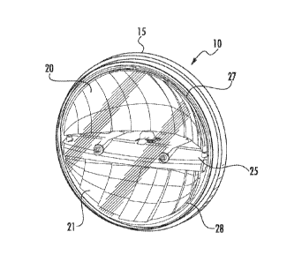
As shown in Figure 1, a first embodiment of a headlamp assembly 10 for a
vehicle includes a 7-in round housing 15 for coupling headlamp assembly 10 to
the vehicle, first and second reflector portions 20 and 21 and a heat sink
structure 25, which is a planar body that bisects housing into upper and lower

areas, 27 and 28. Heat sink structure 25 supports light emitting diode
assemblies and a circuit board, as will be discussed in detail below. Headlamp

assembly includes a lens 30. Lens 30 may be formed of a hard-coated
polycarbonate that is glued to housing 15 using a two component urethane. In
one embodiment, lens 30 includes a copper wire heating element for melting
snow or ice.
One embodiment of heat sink structure 25 is illustrated in figures 2-5. In
particular, heat sink structure 25 includes a first surface 35 (figure 2) and
a
second surface 36 (figure 3). Heat sink structure 25 also includes a housing
abutting edge 40 which is made up of first and second side edges, 42 and 43,
3

CA 02861948 2013-08-08
WO 2012/145056
PCT/US2012/024484
first and second curved edges, 47 and 48, and back edge 49. Side edges 42
and 43 also include alignment ribs 50 for aligning heat sink structure 25
within
housing 15.
Planar heat sink 25 also includes a substantially straight edge 51, which is
positioned near lens 30 in headlamp assembly 10. As illustrated in Figure 3,
first
surface 35 includes a first light emitting diode receiving portion 55, which
may
take the form of an indented area sized to receive a light emitting diode.
Alignment posts, 57 and 58, may be formed in first light emitting diode
receiving
portion 55 for aligning with datum features in a first light emitting diode
assembly
65. Thus, first light emitting diode assembly 65 may be accurately located on
heat sink structure 25. In addition, first light emitting diode receiving
portion 55
has holes 68 and 69 formed therein for accepting fasteners, 70 and 71, used
for
securing first light emitting diode assembly 65 to heat sink structure 25 in
the
same plane as first surface 35. First surface 35 also includes fastener
receiving
channels 73 and 74 for facilitating the attachment of screws for joining heat
sink
structure 25 and housing 15. A front angled portion 75 of heat sink structure
25
is located near substantially straight edge 51. Upstanding supports 77 and 78
are also formed at each side of front angled portion 75 for supporting first
reflector portion 20, as will be described in detail below. Heat sink
structure 25
also includes apertures 79 and 80 for receiving fasteners, generally indicated
at
81, for securing first and second reflector portions, 20 and 21, to heat sink
structure 25. An additional aperture 82 is located adjacent to back edge 49 of

housing abutting edge 40 of heat sink structure 25. Aperture 82 is adapted to
4

CA 02861948 2013-08-08
WO 2012/145056
PCT/US2012/024484
receive alignment projections 83 and 84 of first and second reflector
portions, 20
and 21, for facilitating the positioning of first and second reflector
portions, 20
and 21, on heat sink structure 25.
As illustrated in Figure 3, the second surface 36 of heat sink structure 25
includes a second light emitting diode receiving portion 85 and a circuit
board
receiving portion 87 formed therein. Second light emitting diode receiving
portion
85 includes alignment posts, 88 and 89, formed therein for aligning with datum

features in a second light emitting diode assembly 90. Apertures 91 and 92 are

also formed therein for accepting fasteners, 93 and 94, used for securing
second
light emitting diode assembly 90 to heat sink structure 25 in the same plane
as
second surface 36. In one embodiment, circuit board receiving portion 87 is
positioned near substantially straight edge 51 of heat sink structure 25 and
light
emitting diode receiving portion 85 is positioned near the housing abutting
edge
40 of the heat sink structure. Thus, second light emitting diode receiving
portion
85 and circuit board receiving portion 87 are adapted to support second light
emitting diode 95 and a circuit board 100 in a same plane as second surface
36.
Figure 4 is an exploded view of heat sink structure 25 with first surface 35
facing up. First light emitting diode assembly 65 is shown above first light
emitting diode receiving portion 55. Alignment posts 57 and 58 correspond to
apertures in first light emitting diode assembly 65. In addition, holes 68 and
69
formed within first light emitting diode receiving portion 55 align with
fastener
alignment features 102 and 103 such that fasteners 70 and 71 may secure first
light emitting diode assembly 65 to heat sink structure 25. In the embodiment

CA 02861948 2013-08-08
WO 2012/145056
PCT/US2012/024484
shown, first light emitting diode assembly 65 is a 1x2 Altilon LED Assembly
manufactured by Philips Lumiled. A thermally conductive compound may be
positioned between heat sink structure 25 and first light emitting diode
assembly
65. The thermally conductive compound may be a material such as thermal
grease, phase change material, thermal epoxy, or thermal tape. An elongated
opening 105 is also formed within first surface 35 of heat sink structure 25.
Elongated opening 105 is formed adjacent to first light emitting diode
receiving
portion 55 along front angled portion 75 of first surface 35 and is adapted to

receive thermal stampings 108 from a combined buss bar and light blinder
assembly 110.
Combined buss bar and light blinder assembly 110 includes a buss bar
portion 111 and a light blinder portion 112. Bus bar portion 111 includes
thermal
stampings 108 that contact first light emitting diode assembly 65 at a first
ends
115 and extend through elongated opening 105 of heat sink structure 25 at a
second ends 117. Second ends 114 contact a circuit board 125 at openings 128
in circuit board 125, thereby forming an electrical connection between first
light
emitting diode assembly 65 and heat sink structure 25. Second ends 114 of
buss bar portion 111 may be soldered to circuit board 125 and first ends 115
of
buss bar portion 111 may be soldered to first light emitting diode assembly
65.
An overmold 127 is positioned over thermal stampings 108 to insulate thermal
stampings from heat sink structure 25, which is formed of a conductive
material.
Overmold 127 may be formed of a material suitable for high temperature
applications, such as a glass filled nylon material. As noted above, first
ends 115
6

CA 02861948 2013-08-08
WO 2012/145056
PCT/US2012/024484
and second ends 117 are left uncovered to provide the necessary electrical
contacts. In one embodiment, thermal stampings 108 are made of tin plated
brass.
Light blinder portion 112 of heat sink structure 25 may be connected to
overmold 127 with an integral extension 130. In one embodiment, light blinder
portion 112 blocks light from approximately (i.e. glare zone) in a photometric

pattern. Light blinder portion 112 may include bottom projections 133 for
contacting first light emitting diode assembly 65. Therefore, light blinder
portion
112 is positioned perpendicular to first light emitting diode assembly 65 as
shown
in figure 6.
Figure 5 is an exploded view of second surface 36 of heat sink structure
25 with second light emitting diode 95 and a circuit board 125 positioned
above
second light emitting diode receiving portion 85 and circuit board receiving
portion 87, respectively. In one embodiment, jumper wires 140 used to make an
electrical connection between second light emitting diode 95 and a circuit
board
125. Alternatively, a ribbon cable, buss bar, or other suitable device may be
used to make an electrical connection.
As illustrated, circuit board receiving portion 87 includes elongated
opening 105, which extends through heat sink structure 25 from fist surface
35.
Second ends 117 of thermal stampings 108 extend through elongated opening
105 such that second ends 117 contact circuit board 100 at that contact first
light
emitting diode assembly 65 at a first ends 115 and extend through elongated
opening 105 of heat sink structure 25 at a second ends 117. In the embodiment
7

CA 02861948 2013-08-08
WO 2012/145056
PCT/US2012/024484
shown, second light emitting diode assembly 95 is a 1x4 Altilon LED Assembly
manufactured by Philips Lumiled.
Figures 6 and 7 illustrate first and second surfaces, 35 and 36, of heat
sink structure 25 in an assembled configuration. In figure 6, first surface 35
is
shown with first light emitting diode assembly 65 positioned within the first
light
emitting diode receiving portion 55. In addition, combined buss bar and light
blinder assembly 110 is shown with buss bar portion 111 extending into and
through elongated opening 105 formed in first surface 35 and light blinder
portion
112 is perpendicular to first light emitting diode assembly 65 such that light

emitted in the 10U to 90U range is shielded.
Figure 7 illustrates second surface 36 having circuit board 100 positioned
within circuit board receiving portion 87. Although not shown, circuit board
100
includes electrical components on each side thereof. In one embodiment a
thermal material, such as a GAP pad, is used on a bottom side of circuit board

100 in order to improve thermal contact between the electrical components and
heat sink structure 25. In the embodiment shown in Figure 7, jumper wires 140
are shown to provide an electrical connection between second light emitting
diode assembly 90 and circuit board 100.
As illustrated in Figures 8a and 8b, headlamp assembly 10 includes first
and second reflector portions, 20 and 21. First reflector portion 20 is a low
beam
reflector and second reflector portion 21 is a high beam reflector. Both first
and
second reflector portions, 20 and 21, are molded and metalized. In addition,
each of first and second reflector portions, 20 and 21, have a complex
reflector
8

CA 02861948 2013-08-08
WO 2012/145056
PCT/US2012/024484
optic design. The complex reflector optical design includes multiple
intersecting
segments. The segments intersect at points that may be profound and visible or

blended to form a uniform single surface. First reflector portion 20 includes
a
heat sink abutting edge 142 having an alignment projections 83 for fitting
within
aperture 82 formed in first surface 35 of heat sink structure 25. Apertures
(not
shown) formed on heat sink abutting edge 142 of first reflector portion 20
align
with apertures 79 and 80 of heat sink structure 25 for receiving fasteners 81
for
securing first reflector portion 20 to heat sink structure 25. First reflector
portion
20 also includes projections, one of which is indicated at 143, formed on heat

sink abutting edge 142 for contacting upstanding supports 77 and 78 formed on
first surface 35 of heat sink structure 25. Similarly, second reflector
portion 21
includes a heat sink abutting edge 145 having alignment projection 84 for
fitting
within aperture 82 formed in second surface 36 of heat sink structure 25.
Additional apertures, 148 and 149, formed within heat sink abutting edge 145
of
second reflector portion 21 align with apertures 79 and 80 of heat sink
structure
25 for receiving fasteners 81 for securing second reflector portion 21 to heat
sink
structure 25.
When assembled, as illustrated in Figures 9a and 9b, heat sink structure
25 is positioned between first and second reflector portions, 20 and 21,
thereby
creating an upper area 27 and a lower area 28. Heat sink structure prevents
light
from upper area 27 area from impinging on second reflector portion 21 and
prevents light from lower area 28 from impinging on first reflector portion
20.
Heat sink abutting edge 143 of second reflector portion 21 contacts heat sink
9

CA 02861948 2013-08-08
WO 2012/145056
PCT/US2012/024484
along heat sink abutting edge 143. However, heat sink abutting edge 142 of
first
reflector portion 20 does not contact heat sink structure 25 at front angled
portion
75 thereof. Thus, projections 143 of first reflector portion 20 contact
upstanding
supports 77 and 78 formed on first surface 35 of heat sink structure 25 such
that
a contact point is provided between front angled portion 75 of heat sink
structure
25 first reflector portion 20. Upstanding supports 77 and 78 provide stability
and
prevent vibration of reflector portion 20. Front angled portion 75 of heat
sink
structure 25 serves to allow light reflected first reflector portion 20 to
fill
foreground photometric requirements.
Figure 10 is an exploded view of headlamp assembly 10 for illustrating the
manner in which heat sink structure 25 and first and second reflector
sections, 20
and 21, are attached to housing 15. As discussed with respect to Figures 3 and

4, heat sink structure 25 includes side edges 42 and 43 having alignment ribs
50
for aligning heat sink structure 25 within housing 15. Housing 15 includes an
alignment member, such as an alignment rib receiving channel, formed on each
end thereof. Therefore, alignment ribs 50 cooperate with alignments members of

housing 15 to ensure that heat sink structure 25 is in a proper position upon
insertion into housing 15. Housing 15 includes bosses formed therein for
aligning with fastener receiving channels 73 and 74 of heat sink structure 25
and
for receiving fasteners, generally indicated at 155, for securing heat sink
structure 25 and housing 15. A flat surface 157 is formed on inner surface 160

of housing for contacting back edge 49 of heat sink structure. A thermally
conductive material, such as thermal grease, phase change material, thermal

CA 02861948 2013-08-08
WO 2012/145056
PCT/US2012/024484
epoxy, or thermal tape, may be placed between back edge 49 of heat sink
structure 25 and flat surface 157 of housing 15. An opening 165 for a wire
seal
170 is also formed within housing 15 to allow wires to exit housing 15.
Housing
15 may be formed of die-cast aluminum that is anodized black for improved
thermal emissivity. Housing 15 also functions as a heat sink for first and
second
light emitting diode assemblies and circuit board 100.
As illustrated in Figure 11, a back surface 172 of housing 15 may include
fins 175 for providing increased surface area and greater heat dissipation.
Housing 15 also functions as a heat sink for first and second light emitting
diode
assemblies, 65 and 90, and circuit board 100. Housing also serves to provide
environmental protection for first and second light emitting diode assemblies,
65
and 90, circuit board 100, and any wiring components. A Gore-Tex patch 173 is
placed within an opening in housing 15 to prevent water from entering headlamp

assembly 10 while allowing water vapor to escape. Housing 15 also provides a
mounting interface for attaching headlamp assembly 10 to a vehicle. In
general,
headlamp assembly 10 is mounted to a vehicle through the use of bucket
assemblies, as is known in the art.
Headlamp assembly 10 is adapted to emit both high and low beams. A
low beam pattern is emitted when first light emitting diode assembly 65 is
illuminated. A high beam pattern is emitted from headlamp assembly when both
first light emitting diode assembly 65 and second light emitting diode
assembly
90 are simultaneously illuminated.
11

CA 02861948 2013-08-08
WO 2012/145056
PCT/US2012/024484
A second embodiment of is generally indicated at 210 in Figure 12.
Headlamp assembly 210 5x7 housing 215 for coupling headlamp assembly 210
to the vehicle, first and second reflector portions 220 and 221; and a planar
heat
sink structure 225 that bisects housing into upper and lower areas, 227 and
228.
Planar heat sink structure 225 supports light emitting diode assemblies and a
circuit board, as will be discussed in detail below. Headlamp assembly 210
includes a lens 230. Lens 230 may be formed of a hard-coated polycarbonate
that is glued to housing 215 using a two component urethane. Optical elements
231 are formed in lens 230 around the perimeter of lens 230 to diffuse light
in the
10U -90U glare zone. In one embodiment, lens 230 includes a copper wire
heating element for melting snow or ice. Headlamp assembly 210 is designed
for mechanical aiming by the use of aiming pads (not shown) on an exterior
surface of lens 230. A mechanical aimed lamp is generally designed to meet
specific photometric requirements.
One embodiment of heat sink structure 225 is illustrated in figures 13-16.
In particular, heat sink structure 225 includes a first surface 235 (figure
13) and a
second surface 236 (figure 14). Heat sink structure 225 also includes a
housing
abutting edge 240 which is made up of first and second side edges, 242 and
243,
first and second curved edges, 247 and 248, and back edge 249. Side edges
242 and 243 also include alignment slots 250 for aligning heat sink structure
225
within housing 215. Heat sink structure 225 also includes a substantially
straight
edge 251, which is positioned near lens 230 in headlamp assembly 210.
12

CA 02861948 2013-08-08
WO 2012/145056
PCT/US2012/024484
As illustrated in Figure 13, first surface 235 includes a first light emitting

diode receiving portion 255, which may take the form of an indented area sized

to receive a light emitting diode. Alignment posts, 257 and 258, may be formed

in first light emitting diode receiving portion 255 for aligning with datum
features
in a first light emitting diode assembly 265. Thus, first light emitting diode

assembly 265 may be accurately located on heat sink structure 225. In
addition,
first light emitting diode receiving portion 255 has holes 268 and 269 formed
therein for accepting fasteners, 270 and 271, used for securing first light
emitting
diode assembly 265 to heat sink structure 225 in the same plane as first
surface
235. A BUSS bar receiving portion 272 is also formed in first surface 235, as
will
be described in more detail below. First surface 235 also includes fastener
receiving channels 273 and 274 for facilitating the attachment of screws for
joining heat sink structure 225 and housing 215. Front upstanding bosses 277
and 278 are also formed adjacent to each of first and second side edges 242
and
243 for receiving fasteners for attaching first reflector portion 220 to heat
sink
structure 225, as will be described in detail below. Heat sink structure 225
also
includes rear upstanding bosses 279 and 280 for receiving fasteners for
securing
first and second reflector portions 220 and 221 to heat sink structure 225.
Wire
channels 281 are also formed within heat sink structure for providing a
passage
for wires 282.
As illustrated in Figure 14, second surface 236 of heat sink structure 225
includes a second light emitting diode receiving portion 285 and a circuit
board
receiving portion 287 formed therein. In the embodiment shown, second light
13

CA 02861948 2013-08-08
WO 2012/145056
PCT/US2012/024484
emitting diode receiving portion 285 is composed of upstanding walls for
surrounding a second light emitting diode 290, which is positioned within
circuit
board receiving portion 287. Second light emitting diode receiving portion 285

includes alignment posts, 288 and 289, formed therein for aligning with datum
features in second light emitting diode assembly 290. Apertures 291 and 292
are
also formed therein for accepting fasteners, 293 and 294, used for securing
second light emitting diode assembly 290 to heat sink structure 225 in the
same
plane as second surface 236. Second surface 236 of heat sink structure 225
also includes apertures 295-298 formed adjacent to housing abutting edge 240
for facilitating the attachment of second reflector portion 221 to heat sink
structure 225.
Figure 15 is an exploded view of heat sink structure 225 with first surface
235 facing up. First light emitting diode assembly 265 is shown above first
light
emitting diode receiving portion 255. Alignment posts 257 and 258 correspond
to
apertures in first light emitting diode assembly 265. In addition, holes 268
and
269 formed within first light emitting diode receiving portion 255 are adapted
to
receive fasteners 270 and 271 for securing first light emitting diode assembly
265
to heat sink structure 225. In the embodiment shown, first light emitting
diode
assembly 265 is a 1x4 Altilon LED Assembly manufactured by Philips Lumiled. A
thermally conductive compound may be positioned between heat sink structure
225 and first light emitting diode assembly 265. The thermally conductive
compound may be a material such as thermal grease, phase change material,
thermal epoxy, or thermal tape. An elongated opening 305 is also formed
14

CA 02861948 2013-08-08
WO 2012/145056
PCT/US2012/024484
through heat sink structure 225, as shown in Figure 14. Elongated opening 305
is formed adjacent to BUSS bar receiving portion 272 and is adapted to receive

thermal stampings 308 from BUSS bar 310.
BUSS bar 310 includes thermal stampings 308 that contact first light
emitting diode assembly 265 at a first ends 315 and extend through elongated
opening 305 of heat sink structure 225 at a second ends 317. Second ends 317
contact a circuit board 325 through elongated opening 305, thereby forming an
electrical connection between first light emitting diode assembly 265 and heat

sink structure 225. First ends 315 of buss bar 310 may be soldered to first
light
emitting diode assembly 265. An overmold 327 is positioned over thermal
stampings 308 to insulate thermal stampings from heat sink structure 225,
which
is formed of a conductive material. As noted above, first ends 315 and second
ends 317 are left uncovered to provide the necessary electrical contacts. In
one
embodiment, thermal stampings 308 are made of tin plated brass.
Figure 16 is an exploded view of second surface 236 of heat sink structure
225 with second light emitting diode 290 and a circuit board 325 positioned
above second light emitting diode receiving portion 285 and circuit board
receiving portion 287, respectively. In one embodiment, a flat ribbon cable
340
is used to make an electrical connection between second light emitting diode
290
and circuit board 325. Alternatively, jumper wires, a buss bar, or other
suitable
device may be used to make an electrical connection. In the embodiment
shown, second light emitting diode assembly 290 is a 1x4 Altilon LED Assembly
manufactured by Philips Lumiled.

CA 02861948 2013-08-08
WO 2012/145056
PCT/US2012/024484
Figures 17 and 18 illustrate first and second surfaces, 235 and 236, of
heat sink structure 225 in an assembled configuration. In figure 17, first
surface
235 is shown with first light emitting diode assembly 265 positioned within
the
first light emitting diode receiving portion 255. In addition, buss bar 310 is
shown
with overmold 327 fitted within BUSS bar receiving portion 272. Wires 282
extend from first light emitting diode assembly 265 through wire channels 281
formed in first surface 235 of heat sink structure 225.
Figure 18 illustrates second surface 236 having circuit board 325
positioned within circuit board receiving portion 287. Although not shown,
circuit
board 325 includes electrical components on each side thereof. In one
embodiment a thermal material, such as a GAP pad, is used on a bottom side of
circuit board 325 in order to improve thermal contact between the electrical
components and heat sink structure 225. In the embodiment shown in Figure 18,
a flat ribbon cable 340 is used to provide an electrical connection between
second light emitting diode assembly 290 and circuit board 325.
As illustrated in Figures 19a and 19b, headlamp assembly 210 includes
first and second reflector portions 220 and 221. First reflector portion 220
is a
low beam reflector and second reflector portion 221 is a high beam reflector.
Both first and second reflector portions 220 and 221 are molded and metalized.

In addition, each of first and second reflector portions 220 and 221 have a
complex reflector optic design. First reflector portion 220 includes a heat
sink
abutting edge 342 having apertures (not shown) formed therein for aligning
with
upstanding bosses 277-280 of first surface 235 of heat sink structure 225.
16

CA 02861948 2013-08-08
WO 2012/145056
PCT/US2012/024484
Fasteners 281 are used to secure first reflector portion 220 to heat sink
structure
225. Similarly, second reflector portion 221 includes a heat sink abutting
edge
345 having apertures 347-350 formed therein for aligning with apertures 295-
298
formed in second surface 236 of heat sink structure 225. Fasteners 281 extend
through the apertures to secure second reflector portion 221 to heat sink
structure 225.
When assembled, as illustrated in Figures 20a and 20b, heat sink
structure 225 is positioned between first and second reflector portions 220
and
221, thereby creating an upper area 227 and a lower area 228 in headlamp
assembly 210. Heat sink structure 225 prevents light from upper area 227 from
impinging on second reflector portion 221 and prevents light from lower area
228
from impinging on first reflector portion 220.
Heat sink abutting edge 345 of second reflector portion 221 contacts heat
sink structure 225 to facilitate fastening of second reflector portion 221 to
first
surface 235 of heat sink structure 225. However, heat sink abutting edge 342
of
first reflector portion 220 does not contact heat sink due to upstanding
bosses
277-280, which are formed on first surface 235 of heat sink structure 225.
Figure 21 is an exploded view of headlamp assembly 210 for illustrating
the manner in which heat sink structure 225 and first and second reflector
section
220 and 221 are attached to housing 215. As discussed with respect to Figures
13 and 14, heat sink structure 225 includes side edges 242 and 243 having
alignment slots 250 for aligning heat sink structure 225 within housing 215.
Housing 15 includes an alignment member, such as an alignment projection 355,
17

CA 02861948 2013-08-08
WO 2012/145056
PCT/US2012/024484
formed on each end thereof. Therefore, alignment slots 250 cooperate with
alignments members 335 of housing 215 to ensure that heat sink structure 225
is
in a proper position upon insertion into housing 215. Housing 215 includes
bosses formed therein, one of which is indicated at 360, for aligning with
fastener
receiving channels 273 and 274 of heat sink structure 225 and for receiving
fasteners, generally indicated at 365, for securing heat sink structure 225 to

housing 215. A thermally conductive material, such as thermal grease, phase
change material, thermal epoxy, or thermal tape, may be placed heat sink
structure 225 and an inner surface 368 of housing 15. An opening 375 for a
wire
seal is also formed within housing 215 to allow wires 282 to exit housing 215.

Housing 215 may be formed of die-cast aluminum that is anodized black for
improved thermal emissivity. Housing 215 also functions as a heat sink for
first
and second light emitting diode assemblies and circuit board 325.
As illustrated in Figure 22, housing 215 includes a Gore-Tex patch 380 is
placed within an opening in housing 215 to prevent water from entering
headlamp assembly 210 while allowing water vapor to escape. Housing 215
serves to provide environmental protection for first and second light emitting

diode assemblies, 265 and 290, circuit board 325, and any wiring components.
Housing 215 also provides a mounting interface for attaching headlamp
assembly 210 to a vehicle.
As discussed above, headlamp 210 emits both a high beam and a low
beam. The low beam function uses only first reflector portion and first light
18

CA 02861948 2013-08-08
WO 2012/145056
PCT/US2012/024484
emitting diode assembly. The high beam function uses both first and second
reflector portion and both first and second light emitting diode assemblies.
Figures 23a and 23b illustrate additional embodiment of the heat sink
structure for a 7-in round headlamp and a 5x7 in headlamp. Figure 23a
illustrates a heat sink 400 having a second side 405. Light emitting diode
receiving portion 407 is formed therein. The remainder of second surface is
hollowed out to allow for various circuit board configurations. Once a circuit

board is selected for heat sink 400, second side of heat sink is filled in to
surround the circuit board. Similarly, figure 23a illustrates a heat sink 500
for a
5x7 headlamp assembly. Second surface 505 is illustrated with light emitting
diode receiving portion formed therein. Once a circuit board configuration is
chosen, the area of second side 505 surrounding the circuit board is filled
in.
Figures 24a-24d illustrate a mounting bucket assembly 600 for headlamp
assembly 10. Figure 24a is a front view of bucket assembly 600 having a
retention spring 605, a mounting ring 608 in which lamp assembly sits, a
vertical
aiming screw 610 and a horizontal aiming screw 612. Figure 24b is a view of
the
bucket assembly 600 of Figure 24a. A bezel or retaining ring 615 is included
to
retain lamp assembly 10 in bucket assembly 600. Apertures 620 are formed in
retaining ring 615 to allow access to vertical aiming screw 610 and horizontal

aiming screw 612. Figure 24c illustrates a back view of bucket assembly 600.
Threaded fasteners 625 are provided for attaching headlamp assembly 10 and
bucket assembly 600 to a vehicle. Figure 24d is a cross-sectional view of
bucket
assembly 600 retaining headlamp assembly 10 therein. Although shown with
19

CA 02861948 2016-08-19
WO 2012/145056
PCT/US2012/024484
respect to the 7-in round headlamp assembly, it should be understood that a
corresponding bucket assembly is available for the 5x7 headlamp assembly.
Although the embodiments of the invention herein has been described
with reference to particular embodiments, it is to be understood that these
embodiments are merely illustrative of the principles and applications of the
present invention. For example, the headlamp assembly may include a housing
of a 4x6 configuration. It is therefore to be understood that the scope of the
claims
should not be limited by the preferred embodiments or the examples, but should
be
given the broadest interpretation consistent with the description as a whole.

Representative Drawing
A single figure which represents the drawing illustrating the invention.
Administrative Status

For a clearer understanding of the status of the application/patent presented on this page, the site Disclaimer , as well as the definitions for Patent , Administrative Status , Maintenance Fee  and Payment History  should be consulted.

Administrative Status

Title Date
Forecasted Issue Date 2017-08-01
(86) PCT Filing Date 2012-02-09
(85) National Entry 2013-08-08
(87) PCT Publication Date 2013-10-26
Examination Requested 2015-02-12
(45) Issued 2017-08-01

Abandonment History

There is no abandonment history.

Maintenance Fee

Last Payment of $347.00 was received on 2024-02-02


 Upcoming maintenance fee amounts

Description Date Amount
Next Payment if standard fee 2025-02-10 $347.00
Next Payment if small entity fee 2025-02-10 $125.00

Note : If the full payment has not been received on or before the date indicated, a further fee may be required which may be one of the following

  • the reinstatement fee;
  • the late payment fee; or
  • additional fee to reverse deemed expiry.

Patent fees are adjusted on the 1st of January every year. The amounts above are the current amounts if received by December 31 of the current year.
Please refer to the CIPO Patent Fees web page to see all current fee amounts.

Payment History

Fee Type Anniversary Year Due Date Amount Paid Paid Date
Application Fee $400.00 2013-08-08
Extension of Time $200.00 2013-12-19
Maintenance Fee - Application - New Act 2 2014-02-10 $100.00 2014-01-22
Registration of a document - section 124 $100.00 2014-05-12
Maintenance Fee - Application - New Act 3 2015-02-09 $100.00 2014-11-26
Request for Examination $800.00 2015-02-12
Maintenance Fee - Application - New Act 4 2016-02-09 $100.00 2016-01-27
Maintenance Fee - Application - New Act 5 2017-02-09 $200.00 2017-01-26
Final Fee $300.00 2017-06-14
Maintenance Fee - Patent - New Act 6 2018-02-09 $200.00 2018-01-29
Maintenance Fee - Patent - New Act 7 2019-02-11 $200.00 2019-02-05
Maintenance Fee - Patent - New Act 8 2020-02-10 $200.00 2020-01-27
Maintenance Fee - Patent - New Act 9 2021-02-09 $204.00 2021-02-01
Maintenance Fee - Patent - New Act 10 2022-02-09 $254.49 2022-02-09
Maintenance Fee - Patent - New Act 11 2023-02-09 $263.14 2023-02-03
Maintenance Fee - Patent - New Act 12 2024-02-09 $347.00 2024-02-02
Owners on Record

Note: Records showing the ownership history in alphabetical order.

Current Owners on Record
TRUCK-LITE CO., LLC
Past Owners on Record
None
Past Owners that do not appear in the "Owners on Record" listing will appear in other documentation within the application.
Documents

To view selected files, please enter reCAPTCHA code :


To view images, click a link in the Document Description column. To download the documents, select one or more checkboxes in the first column and then click the "Download Selected in PDF format (Zip Archive)" or the "Download Selected as Single PDF" button.

List of published and non-published patent-specific documents on the CPD .

If you have any difficulty accessing content, you can call the Client Service Centre at 1-866-997-1936 or send them an e-mail at CIPO Client Service Centre.


Document
Description 
Date
(yyyy-mm-dd) 
Number of pages   Size of Image (KB) 
Maintenance Fee Payment 2020-01-27 1 33
Abstract 2013-08-08 2 84
Claims 2013-08-08 16 586
Drawings 2013-08-08 21 951
Description 2013-08-08 20 726
Representative Drawing 2013-08-08 1 34
Cover Page 2014-10-06 1 62
Description 2016-08-19 20 737
Claims 2016-08-19 13 508
Final Fee 2017-06-14 2 44
Representative Drawing 2017-07-06 1 26
Cover Page 2017-07-06 1 60
PCT 2013-08-08 16 1,284
Assignment 2013-08-08 3 82
Fees 2014-01-22 1 43
Correspondence 2013-12-19 2 56
PCT 2013-09-19 1 28
Assignment 2014-05-12 8 524
Correspondence 2014-08-20 18 724
PCT 2014-02-07 1 22
Correspondence 2014-09-12 1 21
Prosecution-Amendment 2015-02-12 2 50
Examiner Requisition 2016-02-19 5 286
Amendment 2016-08-19 18 699