Note: Descriptions are shown in the official language in which they were submitted.
1
1 DYNAMIC TURBULENCE ENGINE CONTROLLER APPARATUSES,
2 METHODS AND SYSTEMS
3 [0001]
4
6
7
8
9 FIELD
[00 02] The present disclosure relates to generation and provision of a flight
plan.
11
12
13
14
16
17
18
19
21
Date Recue/Date Received 2020-04-15
2
1 BACKGROUND
2 [0003] Turbulence forecasting methods focus on discrete areas of
turbulence,
3 such as clear air turbulence (CAT) or thunderstorm regions, and rely
primarily on pilot
4 reports (PIREPS) and other subjective/ observational data for determining
turbulent
airspace regions. Such forecasting turbulence forecasting methods are
unreliable for the
6 purpose of developing a flight plan.
7
8
9 BRIEF DESCRIPTION OF THE DRAWINGS
[o 004] The accompanying appendices and/or drawings illustrate various non-
ii example, inventive aspects in accordance with the present disclosure:
12 [o 005] FIGURE IA provides an overview of an aspect of the DTEC;
13 [o 006] FIGURE lB provides an overview diagram illustrating example
enhanced
14 turbulence regions affecting aircraft and an example output of integrated
turbulence
output in some embodiments of the DTEC;
16 [o 007] FIGURE 2 shows a data flow diagram illustrating an example of a
DTEC
17 accepting inputs and data requests and outputting both predictive and
(near) real-time
18 data in some embodiments of the DTEC.
19 [o 008] FIGURE 3 shows a data flow diagram illustrating an example of a
DTEC
utilizing both external and internal data repositories for input while
accepting inputs
Date Recue/Date Received 2020-04-15
CA 02896761 2015-06-26
WO 2014/106273 PCMJS2013/078546
3
1 and data requests and outputting both predictive and (near) real-time data
in some
2 embodiments of the DTEC;
3 [0009] FIGURE 4A demonstrates a logic flow diagram illustrating example DTEC
4 turbulence calculation integration component, accepting input and outputting
grid
point enhanced turbulence data in some embodiments of the DTEC;
6 [0010] FIGURE 4B provides example output from an enhanced above-storm
7 turbulence determination;
8 [0011] FIGURE 5 demonstrates an example user interface where turbulence
9 prediction is integrated into an existing and/or future flight planning
tool, allowing
o users to alter flight path creation to account for projected turbulence in
some
11 embodiments of the DTEC;
12 [o 012] FIGURE 6 shows a logic flow diagram illustrating an example of a
DTEC
13 integrating turbulence modeling into flight path creation, facilitating
user preference in
14 flight planning variation in some embodiments of the DTEC;
[o 013] FIGURE 7 shows an overview diagram illustrating an example of a
vertical
16 air region and the overlay of turbulent areas affecting aircraft at various
altitudes and
17 times, where overlapping regions illustrate enhanced turbulence in some
embodiments
18 of the DTEC;
19 [0014] FIGURE 8 shows example grid outputs of the mathematical models both
pre and post integration, illustrating how enhanced turbulence is more than
graphical
21 intersection and represents both cumulative and heightened turbulence in
overlay
22 zones in some embodiments of the DTEC;
CA 02896761 2015-06-26
WO 2014/106273 PCMJS2013/078546
4
1 [0 015] FIGURE 9 shows an example data flow diagram of various output media
2 provided by the DTEC and the use of its data in multiple intermediate and
end stage
3 applications in some embodiments of the DTEC;
4 [0 016] FIGURES loA-B and iiA-D show various example and/or visual
input/output component aspects of the DTEC;
6 [0017] FIGURE 12 provides an example logic flow for a real-time flight
alerting
7 and planning component of the DTEC; and
8 [0018] FIGURE 13 shows a block diagram illustrating embodiments of a DTEC
9 controller.
[0019] The leading number of each reference number within the drawings
ii indicates the figure in which that reference number is introduced and/or
detailed. As
12 such, a detailed discussion of reference number 101 would be found and/or
introduced
13 in Figure 1. Reference number 201 is introduced in Figure 2, etc.
14
CA 02896761 2015-06-26
WO 2014/106273 PCMJS2013/078546
1 DETAILED DESCRIPTION
2 DYNAMIC TURBULENCE ENGINE CONTROLLER (DTEC)
3 [0020] In some embodiments, the DYNAMIC TURBULENCE ENGINE
4 CONTROLLER ("DTEC") as disclosed herein transforms weather, terrain, and
flight
5 parameter data via DTEC components into turbulence avoidance optimized
flight
6 plans. In one implementation, the DTEC comprises a processor and a memory
7 disposed in communication with the processor and storing processor-issuable
8 instructions to receive anticipated flight plan parameter data, obtain
terrain data based
9 on the flight plan parameter data, obtain atmospheric data based on the
flight plan
parameter data, and determine a plurality of four-dimensional grid points
based on the
ii flight plan parameter data. The DTEC may then determine a non-dimensional
12 mountain wave amplitude and mountain top wave drag, an upper level non-
13 dimensional gravity wave amplitude, and a buoyant turbulent kinetic energy.
The
14 DTEC determines a boundary layer eddy dissipation rate, storm velocity, and
eddy
dissipation rate from updrafts, maximum updraft speed at grid point
equilibrium level
16 and storm divergence while the updraft speed is above the equilibrium level
and
17 identify storm top. The DTEC determines storm overshoot and storm drag,
Doppler
18 speed, eddy dissipation rate above the storm top, and determine eddy
dissipation rate
19 from downdrafts. The DTEC then determines the turbulent kinetic energy for
each grid
point and, as illustrated in Figure 1A, identifies an at least one enhanced
flight plan
21 based on the flight plan parameter data and the determined turbulent
kinetic energy.
CA 02896761 2015-06-26
WO 2014/106273 PCMJS2013/078546
6
1 [0 0 2 1] Turbulence forecasting methods may focus on discrete areas of
turbulence,
2 such as clear air turbulence (CAT) or thunderstorm regions, and rely
primarily on pilot
3 reports (PIREPS) and other subjective/observational data for determining
turbulent
4 airspace regions. The DTEC as disclosed herein utilizes unique predictive
components
and determinations of turbulence in four-dimensional space-time and utilizes
these
6 predictive models to generate a comprehensive forecasting map display and/or
overlay
7 that is not merely the visual combination of disparate turbulence
projections, but is a
8 multi-hazard calculated integration of enhanced turbulent regions, providing
an
9 accurate, multi-dimensional model of turbulence over a specified
spatial/temporal
area.
ii [ o o 2 2] The term "turbulence" as a haphazard secondary motion caused by
the
12 eddies of a fluid system has often been treated as a singular event in
casual
13 connotation, caused by passage through an entropic weather system or by
proximity to
14 shifting air flow patterns. This definition is commonly perpetuated by many
turbulence
forecast platforms that focus on a specific type of turbulence, such as CAT,
without
16 accounting for additional turbulence factors, nor how multi-hazards
conflagrate into
17 not just a series of turbulence events, but an enhanced system which
continues to flux.
18 In Figure iB, wind 102, thunderstorms 103, and gravity waves 103 (the
interaction of
19 media, such as the ocean and the atmosphere caused by energy transfer, on
which
zo gravity acts as a restoring force) can all be turbulence contributors to a
region of three-
21 dimensional space over a specified time. An aircraft 101 traveling through
this region
22 may experience multiple turbulence hazards 105. A turbulence forecast
display that
23 indicates only CAT with gravity wave interference may display a low hazard
area into
24 which an aircraft may be moving. Similarly a weather prediction display may
also fail to
CA 02896761 2015-06-26
WO 2014/106273 PCMJS2013/078546
7
1 factor in the additional risk of CAT. In one embodiment of the disclosed
DTEC, a CAT
2 component producing color-coded terminal display of turbulence hazard over a
3 specified area (where clear may indicate no turbulence, green may indicate
low
4 turbulence hazard, yellow may indicate medium turbulence hazard, and red may
indicate high turbulence hazard) 106 may be integrated with a mountain wave
6 forecasting component which produces a similar color-coded terminal display
107,
7 resulting in an integrated display where the resulting hazard matrix 108 may
not be an
8 overlay of the individual turbulence predictions, but an enhanced turbulence
forecast
9 where individual areas of low or no hazard turbulence may now indicated high
hazard
io turbulence 109. In some embodiments, multiple turbulence overlay displays
may be
ii available showing individuated turbulence forecasts without enhancement. In
some
12 embodiments of the disclosure, only enhanced turbulence forecast displays
may be
13 available. In some embodiments of the disclosure, users may be able to
switch between
14 individuated turbulence forecasts and enhanced turbulence forecasts.
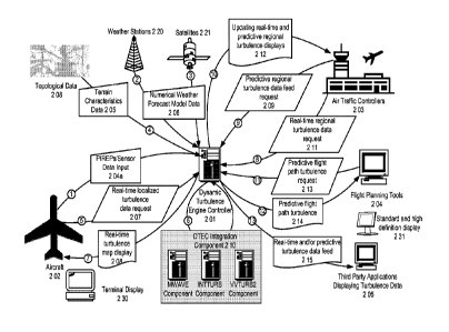
[0 023] In some embodiments of the disclosure, the DTEC 201 may be available
to
16 aircraft 202, air traffic controllers 203, flight planning tools and
software 204, third
17 party applications 205 where turbulence feed incorporation is contributing,
and the
18 like. Figure 3 shows that in some embodiments of the disclosure, PIREPS and
sensor
19 data of aircraft in real-time turbulence conditions 204a may send data to
the DTEC to
be incorporated into the DTEC aggregate data analysis. Similarly in some
embodiments
21 of the disclosure, additional/other sources of input may be weather
stations 220 and
22 satellites 221 which may provide numerical weather forecast model data 206
to the
23 DTEC. In one embodiment, an array of sensors both local and remote may be
24 periodically polled by the aircraft itself, directly by the DTEC, and/or
the like. The
CA 02896761 2015-06-26
WO 2014/106273 PCMJS2013/078546
8
1 polled array of sensors may include, for example, sensors for measuring
altitude,
2 heading, speed, pitch, temperature, barometric pressure, fuel consumption,
fuel
3 remaining for flight, number of passengers, aircraft weight, and/or the
like. In some
4 embodiments of the DTEC, additional/other sources of input may be
topological data
208 which may provide terrain characteristic data 205 to the DTEC. In some
6 embodiments of the DTEC, the receipt of this input may occur prior to
requests to the
7 DTEC for turbulence forecasting. In some embodiments of the DTEC, the
receipt of this
8 input may be ongoing during requests to the DTEC for turbulence forecasting.
In some
9 embodiments of the DTEC, receipts of input may be both before requests to
the DTEC
for turbulence forecasting and ongoing during forecasting requests. In some
11 embodiments, an aircraft 202 may request (near) real-time localized
turbulence data
12 207, an air traffic control system 203 may request predictive regional
turbulence data
13 as an updating feed 209 and/or a (near) real-time regional turbulence data
request 211,
14 a flight-planning tool or software may request predictive turbulence within
a flight path
region or along a flight path course 213. In some embodiments, the DTEC may
direct
16 such requests through a turbulence integration component, e.g., 210, where
DTEC
17 components such as MWAVE component, INTTURB component, and VVTURB2
18 component process input into eddy dissipation rate (EDR) values and render
them for
19 terminal 230, standard/high-definition 231, and/or displays of the like. An
example
zo real-time turbulence request 211, substantially in the form of an HTTP(S)
POST
21 message including XML-formatted data, is provided below:
22 POST /realtime_turbulence_request.php HTTP/1.1
23 Host: www.dtec.com
24 Content-Type: Application/XML
Content-Length: 667
CA 02896761 2015-06-26
W02014/106273
PCT/US2013/078546
9
1 <?XML version = "1.0" encoding =
2 <realtime_turbulence_request>
3 <timestamp>2025-12-12 15:22:43</timestamp>
4 <message_credentials type=" api_key"
<auth_key>h767kwjiwnfe456#niimidrtsxbi</auth_key>
6 </message credentials>
7 <realtime_turbulence_component_params>
8 <sensors_local count="2"
9 <sensor_location sensor_type="airframe_integrated_gps'>
<lat va1="5.4545" I>
11 <lon val="23.6354" />
12 </sensor location>
13 <sensor_speed sensor_type="pitot_tube" location="starboard_wing"
14 <reading t="0" val="554" unit="km-hr" I>
<reading t="-20" val="520" unit="km-hr" I>
16 <reading t="-60" val="488" unit="km-hr" I>
17 </sensor speed>
18 </sensors_local>
19 <sensors_remote count="2"
<sensor_temperature>
21 <reading location="current" alt="2000m" val="20" unit="C" \>
22 <reading location="flightPath+20km" alt="2000m" va1="18" unit="C' \>
23 <reading location="flightPath+100km" alt="2000m" val="22" unit="C" \>
24 <reading lat="45.5454" lon="22.565" alt="0m" val="27" unit="C" \>
</sensor temperature>
26 <sensor windspeed>
27 <source type="NOAA national weather forecast" when="instantaneous"
28 <reading lat="45.548" lon="21.889" speed="22" direction="SSW" />
29 <reading lat="45.448" lon="21.789" speed="18" direction="SW" I>
<reading lat="45.348" lon="21.689" speed="18" direction="SSW"
31 </source>
32 </sensor windspeed>
33 </sensors_remote>
34 <input currentFlightRoutePlan>
<track num="1" heading="092deg" dist="52km" alt="9144m" \>
36 <track num="2" heading="092deg" dist="135km" alt="10200m" \>
37 <track num="3" heading="075deg" dist="200km" alt="7144m" \>
38
CA 02896761 2015-06-26
WO 2014/106273 PCMJS2013/078546
1 <track num="n" heading="092deg" dist="52km" alt="9144m" \>
2 </input currentFlightRoutePlan>
3 <input terrain source="flight_plan_software_map">
4 <terrain_grid size="5x5" unit="10km"
5 <1_1 groundAboveSeaLevel="400m" />
6 <1_2 groundAboveSeaLevel="320m" />
7 <1_3 groundAboveSeaLevel="380m" I>
8 <14 groundAboveSeaLevel="390m" I>
9 <1_5 groundAboveSeaLevel="460m"
10 <2_1 groundAboveSeaLevel="410m" />
11 <n_n groundAboveSeaLevel="285m" I>
12
13 </terrain_grid>
14 </input terrain>
<component request>
16 <generate val="predictive_flight_turbulance" I>
17 <generate val="turbulence_map" />
18 </component request>
19 </realtime_turbulence_component_params>
</realtime turbulence request>
21
22 [o 024] In some embodiments, the DTEC may return a real-time/near real-time
23 turbulence map 208 terminal display to an aircraft, a predictive and
updating regional
24 data feed 212 to an air traffic controller, a predictive flight path
turbulence 214 display
to a flight-planning tool/software, a turbulence data feed 215 to a third
party
26 application displaying turbulence data, and/or the like. An example
predictive flight
27 path turbulence response 214, substantially in the form of an HTTP(S) POST
message
28 including XML-formatted data, is provided below:
29 POST /predictive_flight_path_turbulence_response.php HTTP/1.1
Host: www.flightplanningserver.com
31 Content-Type: Application/XML
32 content-Length: 667
33<?XML version = "1.0" encoding =
CA 02896761 2015-06-26
WO 2014/106273
PCMJS2013/078546
11
1 <predictive_flight_path_turbulence_response>
2 <timestamp>2025-12-12 15:22:43</timestamp>
3 <message_credentials type=" api_key"
4 <auth_key>h767kwjiwnfe456#niimidrtsxbi</auth_key>
</message_credentials>
6 <predictive_flight_patli_turbulance>
7 <flightPatli_option num="1" type="current_path">
8 <track num="1" heading="092deg" dist="52km" alt="9144m" \>
9 <predicted_turbulent_kenrgy val="1.19" I>
</track>
11 <track num="2" heading="092deg" dist="135km" alt="10200m" \>
12 <predicted_turbulent_kenrgy val="1.30" I>
13 </track>
14 <track num="3" heading="075deg" dist="200km" alt="7144m" \>
<predicted_turbulent_kenrgy val="0.89" I>
16 </track>
17
18 </flightPatli_pption>
19 <flightPatli_option num="2" type="minimum_turbulance">
<track num="1" heading="088deg" dist="48km" alt="9144m" \>
21 <predicted_turbulent_kenrgy val="0.45" I>
22 </track>
23 <track num="2" heading="097deg" dist="135km" alt="10200m" \>
24 <predicted_turbulent_kenrgy val="0.68" I>
</track>
26 <track num="3" heading="060deg" dist="180km" alt="7144m" \>
27 <predicted turbulent kenrgy val="0.49" I>
28 </track>
29
</flightPath_pption>
31 <flightPath_option num="3" type="minimum_route_deviation"
32 <track num="1" heading="089deg" dist="42km" alt="9000m" \>
33 <predicted_turbulent_kenrgy val="1.02" I>
34 </track>
<track num="2" heading="097deg" dist="135km" alt="10200m" \>
36 <predicted_turbulent_kenrgy val="1.20" I>
37 </track>
38 <track num="3" heading="077deg" dist="200km" alt="7144m" \>
CA 02896761 2015-06-26
WO 2014/106273 PCMJS2013/078546
12
1 <predicted_turbulent_kenrgy val="0.87" I>
2 </track>
3
4 </flightPath_option>
</predictive_flight_path turbulence>
6 </preclactave flight path turbulence response>
7
8 [0 025] Figure 3 shows an alternate embodiment of DTEC data flow in which
input
9 is gathered through like sources 304, 320, 321, 308, such as in Figure 2 and
these
io inputs may be stored in various current and historical databases systems
340 which in
ii some embodiments of the disclosure may be integrated with the DTEC. In some
12 embodiments of the disclosure, the database systems storing turbulence
input may be
13 separate from, but accessible to, the DTEC. Similar parties 302, 303, 304,
as in Figure
14 2 may request data from the DTEC which may access the database systems for
input
values in addition to directing the requests through its integration component
310. As
16 in Figure 2, the DTEC may return these requests with turbulence forecasts
in a variety
17 of formats to requesting parties.
18 [0 026] In Figure 4A, one embodiment of the DTEC's turbulance integration
19 component is put forth. Beginning with turbulence data input 401 as derived
from such
sources as user application input 401a, weather 401b, terrain 4o1c,
PIREPs/aircraft
21 sensors 401d, and/or the like, which may provide the DTEC with four-
dimensional grid
22 points (three-dimensional space plus time), temperature, winds, humidity,
topography,
23 current turbulent conditions, historical conditions, and/or the like, the
DTEC may first
24 process the input through a mountain wave turbulence component (MWAVE). The
system computes the non-dimensional mountain wave amplitude (dr.) 402 and
CA 02896761 2015-06-26
WO 2014/106273 PCMJS2013/078546
13
computes the mountain top wave drag 403. The following example code fragment
2 shows one embodiment of a methodology for such processing:
3C
4 C* a is the non-dimensional wave amplitude (at mountain top)
5C
6 a (i,m,n) = stabO*h (m, n) /spd0
7 h0 (m, n) = a(1,m,n)
8C
9 C* ddrct is the wind and mountain top wind direction difference
C
11 ddrct = ABS (circt-drct 0 (m,n) )
12 IF ( (ddrct . lt . 90.0) . or . (ddrct .gt. 270.0) ) THEN
13 C
14 C* a above the mountain top is adjusted for stability, wind,
C* and density changes.
16 C
17 a ( 1,m, n) = stab*h (m, n) /spd/COS (ddrct*DTR)*
18 + SQRT (pnu0 (m, n) / (pmodel*stab*spd) )
19 ELSE
a (i,m,n) = 0.0
21 END IF
22 C
23 C* maximum a is 2.5
24 C
IF ( a(i,m,n) .gt. 2.5 ) a (i,m,n) = 2.5
26 C
27 C* Find max ' a' below hOmax.
28 C
29 IF (11 .1t. nlyrs) THEN
amax0 = a (11,m, n) - (zsdg (11, m, n) -hOmax) /
31 + (zsdg ( 11, m, n) -zsdg ( 11+1,m, n) )*
32 + (a (11,m,n)-a(11-F1,m,n) )
33 111 = 11
34 DO i = 11, 1, -1
IF ( (a (i,m,n) .ne . RMISSD) and.
36 -F (a (i, n) amax0) ) THEN
CA 02896761 2015-06-26
WO 2014/106273
PCMJS2013/078546
14
1 111 = i-1
2 amax0 = a (i,m,n)
3 END IF
4 END DO
6 C* 'a' is increased at all levels below max 'a'.
7C
8 DO i = 111,1,-1
9 IF (a (i,m,n) .ne. RMISSD) THEN
10 a (i,m,n) = amax0
11 enhc (i,m,n) = 1.0
12 END IF
13 END DO
14 END IF
15 C
16 C* Find .75 vertical wavelength (and 1.75, 2.75, 3.75).
17 C
18 zrefl = (nn -F .75)*lambda(m,n) + elv(m,n)
19 11 = 1
20 DO i = 1,nlyrs
21 IF ( zsdg(i,m,n) zrefl ) 11 = i
22 END DO
23 IF (11 .1t. nlyrs) THEN
24 ar = a(11,m,n) - (zsdg(11,m,n)-zrefl)/
25 + (zsdg (11, m, n) -zsdg (11+1, m, n) ) k
26 + (a(11,m,n)-a(11+1,m,n))
27 C
28 C* Find .50 vertical wavelength (and 1.50, 2.50, 3.75) .
29 C
30 zhalf = (nn -F .50)fiambda(m,n) + elv(m,n)
31 111 = 1
32 DO i = 1,11
33 IF ( zsdg(i,m,n) .1t. zhalf ) 111 = i
34 END DO
35 ahalf = a (111,m, n) - (zsdg (111,m,n) -zhalf) /
36 + (zsdg(111,m,n)-zsdg(111+1,m,n))*
37 + (a (111,m, n) -a (111+1, m, n) )
38 C
CA 02896761 2015-06-26
WO 2014/106273 PCMJS2013/078546
1 C* 'a' is increased by reflected 'a' if layered
2C* favorably.
3C
4 IF ( ( ahalf .1t. ar ).and.( ahalf .lt. 0.85 ) }THEN
5 rcoeff = (ar-ahalf)**2/(ar+ahalf)**2
6 refl = rcoeff*ar
7 havrfl = .true.
8 DO i = 11,1,-1
9 IF ( (a(i,m,n) .ne. RMISSD) .and.
10 + (havrfl) ) THEN
11 arfl = a(i,m,n) + refl
12 a (1,m,n) = arfl
13 IF ( a(i,m,n) .gt. 2.5 ) a(i,m,n) = 2.5
14 enhc (i,m,n) = 1.0
15 END IF
16 END DO
17 C
M C* Compute mountain top wave drag
M C
drag (m,n) = PI/4.0*h(m,n)*pnu0(m,n)
21 [0027]
22 [0028] In some embodiments of the DTEC, output obtained from the MWAVE
23 component may then be directed into an integrated turbulence calculation
component
24 (INITURB), which will compute upper level non-dimensional gravity wave
amplitude
(al) 404, and sum amv and aui into (a) to determine buoyant turbulent kinetic
energy
26 (TKEbuoy) 405. If a is greater than 1 406, then TKEbuoy = TKEmv + TKEui-
buoy 407.
27 Otherwise, TKEbuoy = o 408. If a greater than amm 409, then TKE = TKEm-wshr
410. The
28 boundary layer eddy dissipation rate (EDR) is computed 411 and if EDRbi is
greater
29 than zero and arm, is not enhanced 412, then the EDR = EDRbi 413, else the
EDR is the
TKE1/3 414.
CA 02896761 2015-06-26
WO 2014/106273 PCMJS2013/078546
16
1 [0029] The following example code fragment shows one embodiment of a
2 methodology for processing of the INITURB determination request:
3C* Non-dimensional L-F amplitude is square root of L-F radiation
4C* divided by constant. Constant is for 20km resolution grads
5C* and is proportionally scaled to resolution of current grid.
6C
7 ahatlf = SQRT(ABS(lfrad)/cc*gdd/20000.)
8C
9C
C* ahat is sum of if and mw ahats
11 C
12 ahat = ahatlf + ahatmw(i)
M C
14 C* Maximum ahat = 2.5
M C
16 IF ( ahat .gt. 2.5 ) ahat = 2.5
17 IF ( ahat .gt. 1.0 ) THEN
M C
19 C* mountain wave tke is proportional to drag.
C
21 tkemw = drag(z)*.0004
22C
BC* Reduce mw drag above this level
24 C
IF ( nhnc(i) .eq. 0.0 )
26 + drag(1) = drag(i)*((2.5-ahat)/1.5)
27 tkebuoy = kh*(ahat-1.0)*bvsq(i) + km*wshrsq(i)
28 + + tkemw
29 IF (ahat .1t. 1.0) THEN tkebuoy = 0.0
tke = km*wshrsq(1)*(1.0 + SQRT(rich)*ahat)**2
31 + -kh*bvsq(i)
32C
33C* Compute layer stability and wind shear
34C
thtamn = ( thta + sfcthta )/2.0
36 bvsq = GRAVTY*thtadf/zdf/thtamn
CA 02896761 2015-06-26
WO 2014/106273 PCMJS2013/078546
17
1 udf = u - sfcu
2 vdf = v - sfcv
3 wshrsq = ( udf*udf + vdf*vdf )/zdfizdf
4C
5C* Compute tke with equation
6C
7 tke = km*wshrsq - kh*bvsq
8C
9C* If the < 0, we've reach top of boundary layer. Set topbl = T
M C
11 IF ( tke .1t. 0.0 ) THEN
12 edrbl = 0.0
13 topbl = .true.
14 ELSE
15 edrbl = tke**.333
16 END IF
17
18 [0030] In some embodiments of the DTEC, output obtained from the MWAVE
19 and INTTURB components may then be processed through a vertical velocity
zo turbulence with perimeter turbulence integration component (VVTURB2). The
storm
21 velocity is computed 415, as is the EDR from computed updrafts 416. The
maximum
22 updraft speed at the grid point equilibrium level (EL) is computed 417.
While the
23 updraft speed is above the EL, the storm's divergence is calculated 418,
after which the
24 storm top is identified 419. Storm overshoot (the storm top minus the storm
EL) and
25 storm drag (the overshoot squared multiplied by the stability between the
EL and
26 storm up squared) are calculated 420. The magnitude of the wind velocity
minus the
27 storm velocity is calculated (known as the Doppler speed) 421. The EDR
above the
28 storm top is computed 422. If there is turbulence within a set distance or
radius, by way
29 of example thirty kilometers, of the storm 423, then the EDR near the storm
is also
30 computed 424. Otherwise, only the EDR from downdrafts is additionally
computed
CA 02896761 2015-06-26
WO 2014/106273 PCMJS2013/078546
18
1 425. Finally, all EDRs computed from INTURB and VVTURB2 components are
2 summed and converted to TKE 426.
3 [43 031] The following exemplary code fragment shows one embodiment of a
4 methodology for processing of the VVTURB2 component:
5C
6C* Compute mean wind near freezing level (estimate of
7C* storm velocity)
8C
9 nlyrs = nlev - 1
DO j = 1, nlyrs
11 CALL ST_INCH ( INT(rlevel(j)), civil, iret )
12 CALL ST_INCH ( INT(rlevel(j+1)), c1v12, iret )
13 pbar = (rlevel(j) + rlevel(j+1))/2.0
14 IF ( pbar .gt. 400. ) THEN
glevel = c1v12///':'//c1v11
16 gvcord = 'PRES'
17 gfunc = 'LAV(TMPC)'
18 CALL DG_GRID ( timfnd, glevel, gvcord, gfunc, pfunc, t,
19 + igx, igy, time, level, ivcord, parm, iret )
gvcord = 'PRES'
21 gfunc = TUR(VLAV(WIND))
22 CALL DG_GRID ( timfnd, glevel, gvcord, gfunc, pfunc, u,
23 + igx, igy, time, level, ivcord, parm, iret )
24 ierr = iret + le=
gvcord = 'PRES'
26 gfunc = WR(VLAV(WIND))
27 CALL DG_GRID ( timfnd, glevel, gvcord, gfunc, pfunc, v,
28 + igx, igy, time, level, ivcord, parm, iret )
29C
30C* Find weighted average of winds in all layers in which
31 C* -5C < t < 5C, weighting layer closer to OC the highest.
32C
33 DO i = 1, maxpts
34 tabs = ABS(t(i))
IF ( tabs .1t. 5.0 ) THEN
CA 02896761 2015-06-26
WO 2014/106273 PCMJS2013/078546
19
1 ufrzl(i) = ufrzl(i) + (5.0 - tabs)*u(i)
2 vfrzl(i) = vfrzl(i) + (5.0 - tabs)*v(i)
3 tsum(i) = tsum(i) + (5.0 - tabs )
4 END IF
END DO
6 END IF
7 END DO
8C* Compute edr from mean vertical velocity
9C
IF ( wmean .gt. 10.0 ) THEN
11 edr (i) = (.035+.0016*(wmean-10.0))**.333
12 ELSE
13 edr (i) = (.0035*wmean)**.333
14 END IF
ELSE
16 edr (i) = 0.0
17 END IF
18 IF (wwnd(i) .gt. maxvv(i)) THEN
19 havtop(i) = .false.
maxvv(i) = wwnd(i)
21 el(i) = z(i)
22 iii=0
23 C
24 C* Divergence above EL is deceleration of the updraft divided by
Ck thickness.
26C
27 ELSE IF ( .not. havtop(i) ) THEN
28 divhi(i) = (vvbase(i)-wwnd(i))/tkns(i)
29 bvsgtop(i) = bvsgtop(i) + bvsq(i)
= + 1
31 ELSE
32 divhi(i) = 0.0
33 END IF
34 C
M C* Define storm top
MC
37 IF ( (maxvv(i) .gt. 1.0) .and. (wwnd(i) .1t. .1)
38 + .and. (.not. havtop(i)) ) THEN
CA 02896761 2015-06-26
WO 2014/106273
PCMJS2013/078546
1 haytop(i) = .true.
2 stmtop(i) = z(i) - tkns(i)/2.0
3 + - tkris(i)*vvbase(i)*Iivbase(i)/wsq
4 ovshoot (i) = stmtop(i) - el (1)
5 IF ( iii .ne. 0 ) THEN
6 bvsqtop(i) = bvsgtop(i)/iii
7 ELSE
8 bvsgtop(i) = 0.0
9 END IF
M C
11 C* Compute storm overshooting drag and storm top relative wind
12C* (relative to freezing level wind)
M C
14 drag (i) = ovshoot(i)*ovshoot(i)*bvsqtop(i)
15 dopu = u(i) - ufrzl(i)
16 dopy ¨ y(i) - yfrzl(i)
17 dopspd = SQRT(dopu*dopu + dopv*dopy)
18 pnu0(i) = dden(i)*SQRT(bvsq(i))*dopspd
19 IF ( (wsq .1e. 0.0) .and. havtop(i) ) THEN
20 stab = SQRT(bysq(1))
21 dopu = u(i) - ufrzl(i)
22 dopy = y(i) - vfrzl(i)
23 dopspd = SORT(dopu*dopu + dopv*dopy)
24 C
25C* Compute EDR above storm top as a function of drag
26C
27 IF (ahat .ge. 1.0) THEN
28 edrtop = (drag(i)*.0004)**.333
29 edr(i) = MAX(edr(1), edrtop)
drag(i) = drag(i)*((2.5-ahat)/1.5)
31 END IF
32C
33C* Compute turbulence near storms if grid distance low enough.
34C
DO I = 1,maxpts
36 IF (edr(i) .ne. RMISSD) THEN
37 gdd = (gdx(i)+gdy(i))/2.0
38 IF ( gdd .1t. 30000. .and. .not.haytop(1)) THEN
CA 02896761 2015-06-26
WO 2014/106273
PCMJS2013/078546
21
1 C
2C* Compute tke near storm using Term 2C of L-F radiation
3C* using same method as in ULTURB.
4C
IF ( MOD(i,igx) .eq. 1 ) THEN
6 ddivdx = (divhi(i+1)-divhi(i))/gdx(i)
7 ELSE IF ( MOD(i,iqx) .eq. 0 ) THEN
8 ddivdx = (divhi(i)-divhi(i-1))/gdx(i)
9 ELSE
ddivdx = (divhi(i+1)-divhi(i-1))/2.0/gdx(i)
11 END IF
12 IF ( i .1e. igx ) THEN
13 ddivdy = (divhi(i+igx)-divhi(i))/gdy(i)
14 ELSE IF ( i .gt. (maxpts-igx) ) THEN
ddivdy = (divhi(i)-divhi(i-igx))/gdy(i)
16 ELSE
17 ddivdy = (divhi(i+igx)-divhi(i-igx))/2.0/gdy(i)
18 END IF
19 crsdiv = -ff(i)*(u(i)*ddivdy - v(i)*ddivdx)
ahat = SQRT(ABS(crsdiv)/cc)
21 IF ( ahat .gt. 2.5 ) ahat = 2.5
22 rich = bvsq(i)/wshrsq(i)
23 IF ( rich .1t. 0.0 ) rich = 0.0
24 IF ( rich .1t. 0.25 ) THEN
amin = 0.0
26 ELSE
27 amin = 2.0 - 1.0/SQRT(rich)
28 END IF
29 IF ( ahat .gt. 1.0 ) THEN
tkebuoy = kh*(ahat-1.0)*bvsq(i) + km*wshrsq(i)
31 ELSE
32 tkebuoy = 0.0
33 END IF
34 IF ( amin .ge. ahat ) THEN
tke = tkebuoy
36 ELSE
37 tke = km*wshrsq(i)*(1.0 + SORT(rich)*ahat)**2
38 + - kh*bvsq(i)
CA 02896761 2015-06-26
WO 2014/106273
PCMJS2013/078546
22
1 END IF
2 IF ( tke .1t. 0.0 ) tke = 0.0
3 edrnear = tke**.333
4 edr(i) = MAX(edr(i),edrnear)
END IF
6 END IF
7 END DO
8C
9C* Compute downdraft velocities (a function of the windex
10C and how far below the freezing level) and downdraft edr
11 C
12 fl = 304.8
13 DO WHILE ( fl .1e. 6097. )
14 CALL ST INCH ( INT(f1), glevel, iret )
gvcord = 'HGHT'
16 gfunc = 'EDR+2'
17 CALL DG_GRID ( timfnd, glevel, gvcord, gfunc, pfunc, edr,
18 + igx, igy, time, klevel, kvcord, parm, iret )
19 DO i = 1, maxpts
IF ( maxvv(i) .gt. 10. ) THEN
21 IF ( fl .gt. sfoz(i) ) THEN
22 wdown = windex(i)*(frzlz(i)-f1)/frzlz(i)
23 IF ( wdown .gt. 10.0 ) THEN
24 edrdown = (.035+.0016*(wdown-10.0))**.333
ELSE IF ( wdown .gt. 0.0 ) THEN
26 edrdown = (.0035*wdown)**.333
27 ELSE
28 edrdown = 0.0
29 END IF
edr (i) = MAX (edr(i), edrdown)
31 END IF
32 END IF
33 END DO
34
CA 02896761 2015-06-26
WO 2014/106273 PCMJS2013/078546
23
1 [0032] The following code fragment shows an additional or alternative
2 embodiment of component embodiments to address above-storm turbulence for
some
3 embodiments, an example image resulting for which is shown in Figure 4B:
4C* Compute turbulence above storm top.
5C
6 IF ( (wsq .1e. 0.0) .and. havtop(z) ) THEN
7 stab = SQRT(bvsq(i))
8 dopu = u(i) - ufrzl(i)
9 dopy = v(i) - vfrzl(i)
dopspd = SQRT(dopukdopu + dopy*dopy)
11 pnu = dden(i)*stabkdopspd
12 IF ( dopspd .eq. 0.0 ) THEN
13 ahat = 2.5
14 ELSE
ahat = ovshoot(i)*stab/dopspd*SQRT(pnu0(1)/pnu)
16 END IF
17 IF (ahat .gt. 2.5) ahat = 2.5
18 IF (ahat .ge. 1.0) THEN
19 edrtop = (drag(i)*.0004)**.333
edr(z) = MAX(edr(1), edrtop)
21 drag(1) = drag(z)*((2.5-ahat)/1.5)
22 END IF
23 END IF
24 END DO
M C
26 [0033]
27 [0034] Figure 5 shows an example of how the DTEC may be incorporated into
28 existing and/or prospect flight planning tools. The DTEC may be included
with online
29 services, with desktop services, with mobile applications, and/or the like.
In this
embodiment of the disclosure, a flight planning tool has an interface 501
representative
31 of an online flight planning service with user profile information. As an
interactive
32 element 502, the DTEC may allow users to factor integrated turbulence
prediction into
CA 02896761 2015-06-26
WO 2014/106273 PCT/US2013/078546
24
1 flight path creation. The DTEC may allow users to consider several ways of
2 incorporating turbulence prediction into their flight path considering their
flight
3 requirements 503. In this example, the DTEC may offer shortest path
generation where
4 turbulence may not be a considering factor in flight path creation,
turbulence
circumvention where turbulence avoidance is a serious flight consideration,
some
6 turbulence circumvention with emphasis on shortest path generation where
turbulence
7 avoidance warrants some consideration, but may not be a primary goal and/or
the like.
8 The DTEC may then generate an enhanced, integrated turbulence forecast
within the
9 specified flight path region 504 and suggest flight path alterations with
respect to the
io level of turbulence circumvention desired.
ii [ o 035] Figure 6 shows one example of an expanded logic flow diagram of
flight
12 path considerations when the DTEC is part of an integrated flight planning
tool. In one
13 embodiment of the disclosure, the flight planning service may access/input
user profile
14 information 600 which may include such information type of aircraft and/or
flight
service such as passenger 601, private 602 and/or commercial cargo/transport
603, the
16 consideration of which may influence turbulence avoidance (i.e. commercial
cargo
17 transport may prioritize shortest path with minimal evasion while passenger
may
18 emphasize discursive turbulence circumvention over speed or directness).
The DTEC
19 may request additional user profile information for flight path
construction 604. In
some embodiments of the disclosure, such information may include the origin
grid
21 point and departure time of the flight, the destination grid point, and/or
the maximum
22 travel time the flight can utilize in constructing its path 605. In some
embodiments of
23 the disclosure, the DTEC may infer user information from previously stored
user
24 profile data and/or prior flight path generation 606. In some embodiments,
this
CA 02896761 2015-06-26
WO 2014/106273 PCT/US2013/078546
1 information may include the aircraft type, its fuel requirements, its
standard flying
2 altitude, previous planned flight paths, and/or the like 6o8. In some
embodiments,
3 user profile and flight creation information that is both input and/or
inferred by the
4 DTEC may be used to update the user profile data for future DTEC use 6o8. In
some
5 embodiments of the disclosure, the DTEC may use other stored profile
information
6 where similar parameters resulted in successful flight path creation. In
some
7 embodiments of the disclosure, the DTEC may use additional input, such as
those from
8 sources external to the flight planning tool, such as historical flight plan
data and/or
9 the like. The DTEC may then calculate the grid size of the region 609 over
which the
10 DTEC may consider flight path creation, using input such as the origin,
destination,
ii maximum flight time, and/or facilities of the aircraft and/or type of
flight. In some
12 embodiments of the disclosure, two dimensional grid space may be considered
for
13 initial path planning purposes. In some embodiments of the disclosure,
three
14 dimensional grid space may be considered for path planning purposes. In
some
15 embodiments of the disclosure, two dimensional grid space may be considered
for
16 initial path planning purposes, which may then be integrated with
additional
17 dimensional information as necessary to accurately determine available grid
space
18 inside which the flight path may still meet flight path parameters.
19 [0 036] In some embodiments of the disclosure, this initial input component
may
zo then be followed by DTEC turbulence integration 6io of the generated
geospatial grid
21 region, some examples of which have been described in Figures 2, 3, and 4.
The DTEC
22 may create an overlay to the generated grid region 611 and may request
additional
23 information about the desired parameters of the flight path through this
grid region
24 612. In some embodiments of the disclosure, these parameters may include
schedule-
CA 02896761 2015-06-26
WO 2014/106273 PCT/US2013/078546
26
1 based path-finding (shortest path immediacy), schedule-based but with
circumvention
2 of acute turbulence (shortest path avoiding high hazard turbulence areas),
discursive
3 turbulence circumvention (navigating out of turbulence areas), and/or any
4 combination of or intermediate stage to these parameters. The DTEC may then
use
available input as described in the input component to determine all flight
path
6 creation parameters 614. The DTEC may then create a flight path over the
integrated
7 turbulence grid region 615, considering flight path creation parameters 613.
The DTEC
8 may then display the proposed flight path to the user as a terminal overlay,
standard or
9 high definition map overlay and/or the like 616, as is applicable to the
flight planning
tool. If the flight path is satisfactory 617, the user may then exit the
flight path planning
11 component of the DTEC as an incorporated flight planning tool option, In
some
12 embodiments of the disclosure, the DTEC may allow the user to export the
determined
13 flight path to other media, save the flight path to the user profile, share
the flight path
14 with additional users, and/or the like. In some embodiments of the
disclosure, if the
proposed flight path is not satisfactory 617, the DTEC may allow the user to
modify
16 flight path creation parameters 618. In some embodiments of the disclosure,
the user
17 may reenter a flight path creation component as specified in earlier steps
612. In some
18 embodiments of the disclosure, users may be allowed to visually manipulate
flight path
19 options using the proposed flight path turbulence grid overlay. In some
embodiments
zo of the disclosure, the user may be able to reenter flight path creation,
visually
21 manipulate the proposed flight path and/or combine these methods in any
22 intermediate path modification.
23 [0 o 3 7] Figure 7 shows an example of a vertical slice dissection of a
proposed flight
24 path through which an aircraft may pass through multiple turbulence types
and where
CA 02896761 2015-06-26
WO 2014/106273 PCT/US2013/078546
27
1 an aircraft may experience enhanced turbulence integration as calculated by
the DTEC.
2 In this example, the aircraft experiences no turbulence at either origin A
701 or
3 destination B 707, but as the aircraft rises through the atmosphere along
the projected
4 flight path, it may begin to encounter turbulence regions. In this example,
between 20
and 30 kilofeet (kft), the aircraft at position 720 has encountered a
thunderstorm
6 region 702. As the aircraft moves directionally forward along its flight
path, it reaches
7 the upper level 704 where CAT may be pronounced. In this example, the
aircraft at
8 position 730 is in an enhanced thunderstorm and upper level CAT region where
9 integrated turbulence as calculated by the DTEC may show greater turbulence
hazard
than either turbulence regions, separately or combined in a conventional
summation.
ii In this example, at position 740 the aircraft has moved into an enhanced
upper level
12 and mountain wave turbulence region 705 which, as calculated by the DTEC,
may show
13 greater turbulence hazard than either turbulence regions, separately or
combined in a
14 conventional summation. At position 750, the aircraft descends in a
mountain
turbulence region where mountain and gravity wave turbulence may be
pronounced. At
16 position 760, the aircraft has arrived at its destination, having
experienced multi-
17 hazard turbulence events in both singular and overlap turbulence regions.
18 [0 038] Figure 8 shows an example grid output of one embodiment of the
DTEC,
19 where integration components may produce staged map overlays of each
component of
the DTEC turbulence calculation process. In some embodiments of the DTEC, the
21 DTEC may show an initial MWAVE grid output 8o1, incorporating MWAVE
turbulence
22 calculations into a singular, non-enhanced turbulence map overlay. In one
embodiment
23 of the DTEC, the map overlay may be color-coded to indicate areas of
turbulence
24 hazard where clear represents no turbulence, green represents light
turbulence hazard,
CA 02896761 2015-06-26
WO 2014/106273 PCT/US2013/078546
28
1 yellow represents moderate turbulence hazard, and red represents severe
turbulence
2 hazard. In some embodiments of the disclosure, the DTEC may output a
forecast as a
3 four-dimensional grid of EDR values in multiple file formats, such as GRIB2
and/or
4 geometric vector data such as Geographic Information System (GIS)
shapefiles, for use
in any GIS display, software, integrator, and/or the like. In one embodiment
of the
6 disclosure, the DTEC may display the results of the integration of its MWAVE
and
7 INTTURB components 802, with enhanced turbulence regions. In some
embodiments
8 of the DTEC, the output may be a color-coded map overlay, export files for
use in
9 geospatial display systems, and/or the like. In one embodiment of the
disclosure, the
DTEC may then display the integration of its INTTURB component with its
VVTURB2
11 component 803. In some embodiments of the DTEC, the output may be a color-
coded
12 map overlay, export files for use in geospatial display systems, and/or the
like. In one
13 embodiment of the disclosure, the DTEC may display a finalized output of
turbulence
14 integration component 804, as described in Figures 2, 3, and 4. In some
embodiments
of the DTEC, the output may be a color-coded map overlay, export files for use
in
16 geospatial display systems, and/or the like. In some embodiments of the
disclosure,
17 these outputs may be available as separate data feeds, software/tool
options, export
18 files and/or the like. In some embodiments of the disclosure, these outputs
may be
19 available internally to the DTEC and only integrated outputs available
externally in the
form of data feeds, software/tool options, export files, and/or the like.
21 [o co 3 9] Figure 9 demonstrates one example of how DTEC integration
22 component(s) may incorporate external data feeds and may provide various
partners,
23 third party software applications/tools, end users, integrators, internal
and external
24 flight planning services, and/or the like with integrated turbulence output
in the form
CA 02896761 2015-06-26
WO 2014/106273 PCT/US2013/078546
29
1 of comma-separated value (CSV), geometric vector data files, gridded binary
(GRIB)
2 format, data feeds, and/or the like. In one embodiment, the DTEC receives
and/or
3 requests global models/modeling data for a variety of weather and/or
geographic
4 models, including but not limited to global models and/or regional models.
In some
embodiments, Global Forecast System (GFS) modeling 901 from the National
Oceanic
6 and Atmospheric Administration (NOAA) is utilized as input. In some
embodiments,
7 the DTEC receives Rapid Refresh (RAP) 902 modeling from the NOAA as input.
In
8 some embodiments, the DTEC receives GEM (Global Environmental Multiscale
Model)
9 as input. In some embodiments, the DTEC receives ECMWF modeling as input. In
one
embodiment, the DTEC receives GFS, RAP, GEM, ECMWF, and/or similar modeling
ii information as input. Some embodiments of the DTEC are model agnostic. In
some
12 embodiments the DTEC produces one or more GRIB2 file(s) 903 and/or record
outputs
13 that may be appended in GRIB format for use in file distribution by DTEC
partners
14 904. In some embodiments, DTEC partners may distribute DTEC output through
various communication networks 905 such as local area networks (LAN) and/or
16 external networks such as the internet which may provide DTEC partners,
third party
17 applications/tools 906, and/or end users 907 with DTEC output. In some
18 embodiments of the DTEC, such output may be in propagated GRIB files as
provided to
19 DTEC partners. In some embodiments of the DTEC, such output may be
converted to a
zo visual form for display on a web browser, smart phone application, software
package
21 and/or the like. In some embodiments of the DTEC, electronic messaging 907
such as
22 email, SMS text, push notifications, and/or the like may be employed to
alert end users
23 of important data updates from the DTEC, DTEC partners, and/or other
parties
24 providing DTEC output data.
CA 02896761 2015-06-26
WO 2014/106273 PCT/US2013/078546
1 [0040] In some embodiments, the DTEC may provide a file or data stream as
2 output, in which values of the DTEC during component production, including
but not
3 limited to EDR finalization, may be recorded or provided. One example of a
DTEC CSV
4 output file is provided below, showing an in-flight time sequence of
forecasted
5 turbulence:
nigh PHX-MSP &.i z3m.7,77,, Leave:0413Z Astive705.45Z.
I u5,-1351e.uce Forecal4 CEER'100)
Thaw. Latitude. L.51.1g.tr.& AINtlxle 1k5:3. MWAYE, CONITURB -3,,V111.33 EN-T7-
3,2aB 1.7,71,a-TL7.3.. B FINAL Expbtraticrs
415 335 -111.5 50 5 0 0 1 1
425 347 -111.5 253 0 3 .3 0 26 26
litm--:4.52-sy,
tuf55-iienct..
435 3.4. -1103 373 0 3 5 0 1 1
M-.3u5-,Farri wave ;:nd
445 33_2 -109 370 3 .r3 1 35. 1 75
free. gravity wa=kre.
.amplittl&s mrabine
435 355 -107.7 373 0 3 0 0 3 0
St-olia
535 37 3 -Eat,- 37;3 0 .3 3 0 34 34
rtishiiInce
Molgriain wave and
51.5 35...1 -104.7 370: 3 0 1 35. 1 35
.freÃ. gravity wave
arap.liavles ,:orn54ie
525 3.2 -153. 373 5 3 1 0 1
535 33.5 -102.3 375 0 45 3 45. 3 45
543 43.9 -101 373 3 -3 1 3 1
555 415 -35.7 373 5 SE 1 -7-, 3 51
633 42.6 -99.5 370: 3 34 3 34 3 34
015 43.5 -37 373 3 30 1 30 1 30
625 444 -95.3 293 0 13 43 10 43 43
535 44.7 -94 134 3 .L: 24 0 24 24
NE.21--,,20Fra
545 44.8 -93.2 25 3 19 5 19 51 51
6 [0041]
EI.34511ies,,:e
7 [0042] In some embodiments of the DTEC, a file or feed (e.g., a CSV file)
output
8 from the DTEC may be provided as input to a geometric vector data generator
907,
9 which may provide additional data output options. In some embodiments of the
DTEC,
10 the geometric vector data generator may output geometric vector data files
to a file
ii server 930 which may provide the data output to an alert server 920 which
may provide
12 the output a communications networks 905 to such partners, third parties,
software
13 applications, end users and/or the like as described. In some embodiments
of the
14 DTEC, the geometric vector data generator may output geometric vector data
files, such
CA 02896761 2015-06-26
WO 2014/106273
PCMJS2013/078546
31
1 as shapefiles, for storage in GIS database(s) 908. In some embodiments of
the DTEC,
2 Web Mapping Services (WMS) and/or Web Feature Services (WFS) 909 may obtain
the
3 geometric vector data files from GIS database(s) and provide geographic
service
4 integrators 911 with DTEC output data through various communication networks
905
as described. In some embodiments of the DTEC, file server(s) 908 and/or WMS
may
6 incorporate the DTEC output data into a DTEC integrated server 940 with
application,
7 data, and/or network components. A DTEC integrated server may employ such
output
8 data from DTEC determination components in proprietary software tools, web
services,
9 mobile applications and/or the like. In one embodiment of the DTEC, a DTEC
integrated server may employ DTEC component output for use in flight planning
tools
11 912, such as AviationSentry Online .
12 [o 043] Figure 10A shows an example terrain height map 1001 in meters over
the
13 Colorado area in the 0.25 deg latitude/longitude grid world terrain
database. In this
14 embodiment of the DTEC, black areas are regions where the terrain is
relatively flat.
[0 044] Figure loB shows two examples of asymmetry in computed terrain height
16 as described in loA along x and y directions. In one embodiment of the
DTEC,
17 asymmetry is computed as the negative height change in the east (x)
direction 1002. In
18 one embodiment of the DTEC, asymmetry is computed as the negative height
change in
19 the north (y) direction 1003.
zo [0045] Figure nA shows one example of a 3-hour RAP model forecast 1101
21 showing
Streamlines and isotachs (kts) of the forecast flow at 250mb (near FL350).
22 [43 046] Figure 11B shows one example of Lighthill-Ford radiation 1102
computed
23 at io668 m (FL35o) for the forecast flow shown in Figure nA. Lighthill-Ford
radiation
CA 02896761 2015-06-26
WO 2014/106273 PCMJS2013/078546
32
1 is the gravity wave diagnostic in ULTURB, a component of the DTEC, in one
2 embodiment of the DTEC.
3 [0047] Figure liC shows one example of ULTURB turbulence forecast 1 103 in
4 EDR values for the forecast flow described in Figure hA. ULTURB, a component
of the
DTEC in one embodiment, combines the gravity wave diagnostic described in
Figure
6 n.B, the Richardson number, and the vertical wind shear.
7 [0048] Figure liD provides an example of output generated by the DTEC, a 4D
8 grid of EDR values, which may be made available in several forms including,
by way of
9 non-limiting example, GRIB2 format and GIS shapefiles. As discussed above,
EDR
io value is the Eddy Dissipation Rate and is defined as the rate at which
kinetic energy
ii from turbulence is absorbed by breaking down the eddies smaller and smaller
until all
12 the energy is converted to heat by viscous forces. EDR is expressed as
kinetic energy
13 per unit mass per second in units of velocity squared per second (m2/53).
The EDR is
14 the cube root of the turbulent kinetic energy (TKE). When adding the EDR
values
together from VVTURB2 and IN1TURB, the values may be converted back to TKE,
16 added together, and converted back to EDR (take the cube root of the sum).
17 [0049] Figure liD also illustrates various interface features that may be
used to
18 navigate the four-dimensional grid, such as a time slider 1110 to move
through various
19 calculated time grids, an elevation slider 1112 to view various elevations,
and a detail
zo widget, to adjust the granularity/detail of the displayed turbulence
interface.
21 110 0 5 0] .. Figure 12 provides an example logic flow for aspects of a
real-time flight
22 alerting and planning component in one embodiment of the DTEC. As
discussed, the
23 DTEC may provide flight planning tools. Additionally or alternatively, the
DTEC may
CA 02896761 2015-06-26
WO 2014/106273 PCMJS2013/078546
33
1 provide flight plan adjustments/modifications and/or alerts if
weather/turbulence
2 determinations change, for example, if an airplane were on a particular
course that,
3 based on real-time turbulence determinations, had become potentially
dangerous.
4 [0051] As shown in the figure, the DTEC alerting component receives (and or
retrieves via response to a database query) current aircraft position 1202
(e.g., flight
6 profile data 1200 from a flight profile database), and may also receive the
previously
7 predicted turbulence for that route (or for an anticipated route if the
actual flight plan
8 is not provided). The DTEC then determines real-time turbulence for the
planned route
9 1204 and compares the predicted turbulence to the real-time turbulence 1206.
If the
io newly determined real-time turbulence does not deviate notably 1208 from
the
I previously predicted/anticipated turbulence, then the process cycles, e.g.,
for a certain
12 period (I min, 2 min, 5 min, 10 min, etc.) or for some other measure such
as location of
13 one or more aircraft, weather events, and/or the like. If the newly
determined real-time
14 turbulence is a notable deviation or significant difference from the
previously predicted
turbulence 1208, then the turbulence is updated 1210 and the process
continues. Note
16 that the threshold difference or deviation may be set by the DTEC or DTEC
17 user/subscriber, and in some embodiments may be any numerical change, while
in
18 other embodiments may be a change or certain magnitude or percentage.
19 [0052] When the turbulence is updated, the DTEC determines if there is a
known
zo or determinable turbulence threshold 1212 for the flight/aircraft. For
example, a
21 commercial passenger aircraft that subscribes to the DTEC may have set a
particular
22 turbulence threshold in the profile, reflecting that passenger aircraft may
wish to avoid
23 significant turbulence for safety and comfort reasons, while a cargo
aircraft may have a
CA 02896761 2015-06-26
WO 2014/106273 PCMJS2013/078546
34
1 much higher threshold and be willing to undertake more turbulence to save
time
2 and/or money. The threshold may also be predicted/determined based on the
airframe
3 and/or airfoil type, the user, the flight plan, fuel resources, alternative
routes, etc. For
4 flights/aircraft that the turbulence threshold either is not known or is not
determinable
1212, the DTEC may have a default (i.e., safety) threshold 1214, and if that
default
6 threshold is exceeded 1214, may issue an alert or notification 1220 to the
aircraft
7 (and/or ground control).
8 [o 053] If the flight turbulence threshold is known 1212 (i.e., the
flight has a
9 subscription or is otherwise registered with the DTEC), the DTEC determines
whether
the turbulence exceeds the specified threshold 1216, and if so, determines if
the flight's
ii route can be adjusted or updated 1218 by the DTEC (e.g., using the flight
path
12 component discussed in Figure 5 and Figure 6) to find the optimal path
based on the
13 desired turbulence profile/threshold and various flight parameters, such as
fuel
14 reserves, destination, aircraft type, etc. If the DTEC is unable or is not
configured to
provide an alternative or adjusted flight plan 1218, an alert or notification
1220 is
16 generated/issued. If the DTEC can adjust or update the flight's route 1218,
the
17 adjusted/modified route is determined 1222 and the flight plan is adjusted
accordingly
18 1224, and updated 1200. Note that, in some embodiments, an adjusted or
modified
19 flight plan (or a selection of plans) may be provided for approval or
selection 1222a.
[4,3 054] In some embodiments, the DTEC server may issue PHP/SQL commands
21 to query a database table (such as FIGURE 13, Profile 1319c) for profile
data. An
22 example profile data query, substantially in the form of PHP/SQL commands,
is
23 provided below:
CA 02896761 2015-06-26
WO 2014/106273 PCMJS2013/078546
1 <?PHP
2 header ('Content-Type: text/plain');
3 mysql_connect("254.93.179.112",$DEserver,$password); // access database
server
4 mysql_select_db("DTEC_DB.SQL"); // select database table to search
5 //create query
6 $query = "SELECT fieldl fie1d2 fie1d3 FROM ProfileTable WHERE user LIKE
'%'
7 $prof";
8 $result = mysql_query($query); // perform the search query
9 mysql_close("DTEC_DB.SQL"); // close database access
10 ?>
11
12 [0055]
13 [0056] The DTEC server may store the profile data in a DTEC database. For
14 example, the DTEC server may issue PHP/SQL commands to store the data to a
15 database table (such as FIGURE 13, Profile 1319c). An example profile data
store
16 command, substantially in the form of PHP/SQL commands, is provided below:
17 <?PHP
18 header ('Content-Type: text/plain');
19 mysql_connect("254.92.185.103",$DBserver,$password); // access database
server
20 mysql_select("DTEC_DB.SQL"); // select database to append
21 mysql_query("INSERT INTO Prof ileTable (fieldnamel, fieldname2,
fieldname3)
22 VALUES ($fieldvarl, $fieldvar2, $fieldvar3)"); // add data to table In
database
23 mysql_close("DTEC_DB.SQL"); // close connection to database
24 ?
26 [0 0 57] Various embodiments of the DTEC may be used to provide real-time,
pre-
27 flight and/or in-flight turbulence reporting, planning and response. The
integrated,
28 unified turbulence system provided by the DTEC may be used in flight
equipment
29 and/or ground equipment. The DTEC may provide weather/aviation decision
support
(e.g., via graphical displays) and/or provide alerts/triggers. Although it is
discussed in
31 terms of re-routing in time of increased turbulence, in some embodiments,
the DTEC
32 may identify more efficient paths based on real-time updates where there is
decreased
CA 02896761 2015-06-26
WO 2014/106273 PCMJS2013/078546
36
1 turbulence over a shorter physical distance, and may update a flight plan
accordingly.
2 The DTEC identifies 4D areas for flight hazards, and a user may choose or
set their
3 profile based on particular hazards (e.g., a passenger airline would have a
different
4 hazard/turbulence profile than an air freight company, and a large airliner
would have
a different profile from a small plane or helicopter). Various cost
calculations and risk
6 calculations may also be used in determining alerts and/or flight paths. In
some
7 embodiments, real-time feedback may come from plane-mounted instrument
sensors
8 and provide updates to predicted turbulence. Such information may be used to
refine
9 component configurations for turbulence determination. Although examples
were
io discussed in the context of jet airliners, it is to be understood that the
DTEC may be
ii utilized for low-level services, such as helicopters, unmanned aerial
vehicles, as well as
12 high speed and/or military aircraft, and may even have potential ground
applications,
13 especially in mountainous terrain. The DTEC may work with air traffic
control,
14 particularly in management of routing. In some embodiments, the DTEC may
input
directly in avionics systems to guide planes.
16 [o o 5 8 ] Prior to the DTEC, forecasts of turbulence, if even
available, were generally
17 qualitative (e.g., light/heavy), independent of aircraft type, and did not
include all
18 sources of turbulence (e.g., they specifically exclude thunderstorms) or
interactions of
19 turbulence, thus making them unusable for most practical applications such
as flight
zo planning. The integrated turbulence forecast of the DTEC is unique because
it
21 dynamically determines the location and level at which each comprehensive
turbulence
22 determination is made, based on the meteorological conditions at that point
in space
23 and time. In some embodiments, the result is a single, integrated forecast
that includes
24 all sources of turbulence, and is produced in quantitative units, such as
Eddy
CA 02896761 2015-06-26
WO 2014/106273 PCMJS2013/078546
37
1 Dissipation Rate (EDR), thus making it suitable for practical uses, such as
flight
2 planning applications, and allows for categorical flexibility specific to an
aircraft.
3 [0059] In some embodiments, the DTEC integrates three DTEC turbulence
4 components, ULTURB, BLTURB, and MWAVE into one component/program called
INTTURB. In some additional or alternative embodiments, the DTEC integrates
6 VVTURB with ULTURB and BLTURB into a component/program called VVINTTURB.
7 Output from all components may in EDR, an aircraft-independent metric of
turbulence
8 intensity. The DTEC may assign an EDR value at each model grid point and at
each
9 flight level. Observations of turbulence may also be used for further tuning
of the
forecast where and when they are available.
ii [o 060] Various embodiments of the DTEC are contemplated by this
disclosure,
12 with the below exemplary, non-limiting embodiments Al-C84 provided to
illustrate
13 aspects of some implementations of embodiments of the DTEC.
14 [0061] At A dynamic turbulence engine controller processor-implemented
flight
planning method, comprising: receiving anticipated flight plan parameter data;
16 obtaining terrain data based on the flight plan parameter data; obtaining
atmospheric
17 data based on the flight plan parameter data; determining a plurality of
four-
18 dimensional grid points based on the flight plan parameter data; for each
point of the
19 plurality of four-dimensional grid point: determining via a processor a non-
dimensional mountain wave amplitude and mountain top wave drag, determining an
21 upper level non-dimensional gravity wave amplitude, determining a buoyant
turbulent
22 kinetic energy, determining a boundary layer eddy dissipation rate,
determing storm
23 velocity and eddy dissipation rate from updrafts, determining maximum
updraft speed
CA 02896761 2015-06-26
WO 2014/106273 PCMJS2013/078546
38
1 at grid point equilibrium level, determining storm divergence while the
updraft speed is
2 above the equilibrium level and identifying storm top, determining storm
overshoot
3 and storm drag, determining Doppler speed, determining eddy dissipation rate
above
4 the storm top, and determining eddy dissipation rate from downdrafts;
determining the
turbulent kinetic energy for each grid point; identifying an at least one
flight plan based
6 on the flight plan parameter data and the determined turbulent kinetic
energy; and
7 providing the identified at least one flight plan.
8 [o 062] A2. The method of embodiment Al, wherein the flight plan parameter
data
9 includes aircraft data.
[o o 63] A3. The method of embodiment A2, wherein the aircraft data includes
ii airframe information.
12 [o 064] A4. The method of embodiment A2 or A3, wherein the aircraft data
13 includes airfoil information.
14 [0065] A5. The method of any of embodiments A1¨A4, wherein the flight plan
parameter data includes take-off time.
16 [0 o66] A6. The method of any of embodiments A1-A5, wherein the flight plan
17 parameter data includes take-off location.
18 [0067] A7. The method of any of embodiments Ai-A6 wherein the flight plan
19 parameter data includes destination location.
zo [o 068] A8. The method of any of embodiments Ai-A7, wherein the flight plan
21 parameter data includes cargo information.
CA 02896761 2015-06-26
WO 2014/106273 PCMJS2013/078546
39
1 [0069] A9. The method of any of embodiments Ai-A8, wherein the flight plan
2 parameter data indicates the flight is a passenger flight.
3 [0070] Ai . The method of any of embodiments Al-A9, wherein the flight plan
4 parameter data indicates the flight is a cargo flight.
[0071] An. A DTEC platform flight planning apparatus, comprising a
processor
6 and a memory disposed in communication with the processor and storing
processor-
7 issuable instructions to: receive anticipated flight plan parameter data;
obtain terrain
8 data based on the flight plan parameter data; obtain atmospheric data based
on the
9 flight plan parameter data; determine a plurality of four-dimensional grid
points based
on the flight plan parameter data; determine a non-dimensional mountain wave
ii amplitude and mountain top wave drag; determine an upper level non-
dimensional
12 gravity wave amplitude; determine a buoyant turbulent kinetic energy;
determine a
13 boundary layer eddy dissipation rate; determine storm velocity and eddy
dissipation
14 rate from updrafts; determine maximum updraft speed at grid point
equilibrium level;
determine storm divergence while the updraft speed is above the equilibrium
level and
16 identify storm top; determine storm overshoot and storm drag; determine
Doppler
17 speed; determine eddy dissipation rate above the storm top; determine eddy
18 dissipation rate from downdrafts; determine the turbulent kinetic energy
for each grid
19 point; identify an at least one flight plan based on the flight plan
parameter data and
zo the determined turbulent kinetic energy; and provide the identified at
least one flight
21 plan.
22 [o 072] Al2. The apparatus of embodiment An, wherein the flight plan
parameter
23 data includes aircraft data.
CA 02896761 2015-06-26
WO 2014/106273 PCMJS2013/078546
1 [0073] A13. The apparatus of embodiment Al2, wherein the aircraft data
includes
2 airframe information.
3 [0074] A14. The apparatus of embodiment Al2 or A13, wherein the aircraft
data
4 includes airfoil information.
5 [0075] A15. The apparatus of any of embodiments A11-A14, wherein the flight
6 plan parameter data includes take-off time.
7 [0076] A16. The apparatus of any of embodiments A11-A15, wherein the flight
8 plan parameter data includes take-off location.
9 [0077] A17. The apparatus of any of embodiments An-A16, wherein the flight
10 plan parameter data includes destination location.
11 [o o 78] A18. The apparatus of any of embodiments A11-A17, wherein the
flight
12 plan parameter data includes cargo information.
13 [0 079] A19. The apparatus of any of embodiments An-A18, wherein the flight
14 plan parameter data indicates the flight is a passenger flight.
15 [o 080] A20. The apparatus of any of embodiment A11-A19, wherein the flight
plan
16 parameter data indicates the flight is a cargo flight.
17 [oo81] A21. A processor-readable tangible medium storing processor-
issuable
18 DTEC flight plan generating instructions to: receive anticipated flight
plan parameter
19 data; obtain terrain data based on the flight plan parameter data; obtain
atmospheric
zo data based on the flight plan parameter data; determine a plurality of four-
dimensional
21 grid points based on the flight plan parameter data; determine a non-
dimensional
22 mountain wave amplitude and mountain top wave drag; determine an upper
level non-
CA 02896761 2015-06-26
WO 2014/106273 PCMJS2013/078546
41
1 dimensional gravity wave amplitude; determine a buoyant turbulent kinetic
energy;
determine a boundary layer eddy dissipation rate; determine storm velocity and
eddy
3 dissipation rate from updrafts; determine maximum updraft speed at grid
point
4 equilibrium level; determine storm divergence while the updraft speed is
above the
equilibrium level and identify storm top; determine storm overshoot and storm
drag;
6 determine Doppler speed; determine eddy dissipation rate above the storm
top;
7 determine eddy dissipation rate from downdrafts; determine the turbulent
kinetic
8 energy for each grid point; and identify an at least one flight plan based
on the flight
9 plan parameter data and the determined turbulent kinetic energy.
o 0821 A22. The medium of embodiment A21, wherein the flight plan parameter
ii data includes aircraft data.
12 [0083] A23. The medium of embodiment A22, wherein the aircraft data
includes
13 airframe information.
14 [0084] A24. The medium of embodiment A22 or A23, wherein the aircraft data
includes airfoil information.
16 [ o 085] A25. The medium of any of embodiments A21-A24, wherein the flight
plan
17 parameter data includes take-off time.
18 [0 086] A26. The medium of any of embodiments A21-A25, wherein the flight
plan
19 parameter data includes take-off location.
zo [0087] A27. The medium of any of embodiments A21-A26, wherein the flight
plan
21 parameter data includes destination location.
CA 02896761 2015-06-26
WO 2014/106273 PCMJS2013/078546
42
1 [0 088] A28. The medium of any of embodiments A21-A27, wherein the flight
plan
2 parameter data includes cargo information.
3 [0089] A29. The medium of any of embodiments A21-A28, wherein the flight
plan
4 parameter data indicates the flight is a passenger flight.
[0 090] A3o. The medium of any of embodiments A21-A29, wherein the flight plan
6 parameter data indicates the flight is a cargo flight.
7 [0 0911 A31. A dynamic turbulence platform flight planning system,
comprising:
8 means to receive anticipated flight plan parameter data; means to obtain
terrain data
9 based on the flight plan parameter data; means to obtain atmospheric data
based on
the flight plan parameter data; means to determine a plurality of four-
dimensional grid
11 points based on the flight plan parameter data; means to determine a non-
dimensional
12 mountain wave amplitude and mountain top wave drag; means to determine an
upper
13 level non-dimensional gravity wave amplitude; means to determine a buoyant
14 turbulent kinetic energy; means to determine a boundary layer eddy
dissipation rate;
means to determine storm velocity and eddy dissipation rate from updrafts;
means to
16 determine maximum updraft speed at grid point equilibrium level; means to
determine
17 storm divergence while the updraft speed is above the equilibrium level and
identify
18 storm top; means to determine storm overshoot and storm drag; means to
determine
19 Doppler speed; means to determine eddy dissipation rate above the storm
top; means
zo to determine eddy dissipation rate from downdrafts; means to determine the
turbulent
21 kinetic energy for each grid point; means to identify an at least one
flight plan based on
22 the flight plan parameter data and the determined turbulent kinetic energy;
and means
23 to provide the identified at least one flight plan.
CA 02896761 2015-06-26
WO 2014/106273 PCMJS2013/078546
43
1 [0 092] A32. The system of embodiment A31, wherein the flight plan parameter
2 data includes aircraft data.
3 [0093] A33. The system of embodiment A32, wherein the aircraft data includes
4 airframe information.
[0094] A34. The system of embodiment A32, wherein the aircraft data includes
6 airfoil information.
7 [0 095] A35. The system of any of embodiments A31-A34, wherein the flight
plan
8 parameter data includes take-off time.
9 [0096] A36. The system of any of embodiments A31-A35, wherein the flight
plan
parameter data includes take-off location.
ii [ o o 9 7] A37. The system of any of embodiments A31-A36, wherein the
flight plan
12 parameter data includes destination location.
13 [0 o 98 ] A38. The system of any of embodiments A31-A37, wherein the flight
plan
14 parameter data includes cargo information.
[0 099] A39. The system of any of embodiments A31-A38, wherein the flight plan
16 parameter data indicates the flight is a passenger flight.
17 [0 olo co] A4o. The system of any of embodiments A31-A39, wherein the
flight plan
18 parameter data indicates the flight is a cargo flight.
19 [00101] A41. A DTEC platform flight planning system, comprising: means to
zo receive anticipated flight plan data; means to obtain atmospheric data
based on the
21 flight plan data; means to determine a plurality of grid points based on
the flight plan
22 data; means to determine turbulent kinetic energy for each grid point;
means to
CA 02896761 2015-06-26
WO 2014/106273 PCMJS2013/078546
44
1 identify an at least one flight plan based on the flight plan data and the
determined
2 turbulent kinetic energy; and means to provide the identified at least one
flight plan.
3 [00102] A42. The system of embodiment A41, comprising: means to determine a
4 non-dimensional mountain wave amplitude and mountain top wave drag.
[00103] A43. The system of embodiment A41 or A42, comprising: means to
6 determine an upper level non-dimensional gravity wave amplitude.
7 [00104] A44. The system of any of embodiments A41-A43, comprising: means to
8 determine a buoyant turbulent kinetic energy.
9 [00105] A45. The system of any of embodiments A41-A44, comprising: means to
determine a boundary layer eddy dissipation rate.
ii [o o io 6] A46. The system of any of embodiments A41-A45, comprising: means
to
12 determine storm velocity.
13 [00107] A47. The system of any of embodiments A41-A46, comprising: means to
14 determine eddy dissipation rate from updrafts.
[0 0108] A48. The system of any of embodiments A41-A47, comprising: means to
16 determine maximum updraft speed.
17 [00109] A49. The system of any of embodiments A41-A47, comprising: means to
18 determine maximum updraft speed at grid point equilibrium level.
19 [00110] A5o. The system of any of embodiments A41-A49, comprising: means to
zo determine storm divergence.
21 [o oil 1] A51. The system of any of embodiments A41-A49, comprising: means
to
22 determine storm divergence while the updraft speed is above the equilibrium
level.
CA 02896761 2015-06-26
WO 2014/106273 PCMJS2013/078546
1 [o 0112] A52. The system of any of embodiments A41-A51, comprising: means to
2 identify storm top.
3 [0 0113 ] A53. The system of any of embodiments A41-A49, comprising: means
to
4 determine storm divergence while the updraft speed is above the equilibrium
level and
5 identify storm top.
6 [0 0114] A54. The system of any of embodiments A41-A53, comprising: means to
7 determine storm overshoot and storm drag.
8 [0 0115 ] A55. The system of any of embodiments A41-A54, comprising: means
to
9 determine Doppler speed.
10 [o 0116 ] A56. The system of any of embodiments A41-A55, comprising: means
to
ii determine eddy dissipation rate above the storm top.
12 [ o 0117] A57. The system of any of embodiments A41-A56, comprising: means
to
13 determine eddy dissipation rate from downdrafts.
14 [00118] A58. The system of any of embodiments A41-A57, wherein the flight
plan
15 data includes aircraft data.
16 [ o 0119] A59. The system of embodiment A58, wherein the aircraft data
includes at
17 least one of airframe information and airfoil information.
18 [0 0120 ] A6o. The system of any of embodiments A41-A59, wherein the flight
plan
19 data includes take-off time.
zo [ o 01 2 1] A61. The system of any of embodiments A41-A6o, wherein the
flight plan
21 data includes take-off location.
CA 02896761 2015-06-26
WO 2014/106273 PCMJS2013/078546
46
1 [0 0122] A62. The system of any of embodiments A41-A61, wherein the flight
plan
2 data includes destination location.
3 [00123] A63. The system of any of embodiments A41-A62, wherein the flight
plan
4 data includes cargo information.
[00124] A64. The system of any of embodiments A41-A63, wherein the flight plan
6 parameter data indicates the flight is a passenger flight.
7 [00125] A65. The system of any of embodiments A41-A63, wherein the flight
plan
8 parameter data indicates the flight is a cargo flight.
9 [00126] Bi. A dynamic turbulence engine processor-implemented method,
io comprising: determining a plurality of four-dimensional grid points for a
specified
11 temporal geographic space-time area; obtaining terrain data based on the
temporal
12 geographic space-time area; obtaining atmospheric data based on the
temporal
13 geographic space-time area; for each point of the plurality of four-
dimensional grid
14 point, determining via a processor a non-dimensional mountain wave
amplitude and
mountain top wave drag; determining an upper level non-dimensional gravity
wave
16 amplitude; determining a buoyant turbulent kinetic energy; determining a
boundary
17 layer eddy dissipation rate; determining storm velocity and eddy
dissipation rate from
18 updrafts; determining maximum updraft speed at grid point equilibrium
level;
19 determining storm divergence while the updraft speed is above the
equilibrium level
zo and identifying storm top; determining storm overshoot and storm drag;
determining
21 Doppler speed; determining eddy dissipation rate above the storm top;
determining
22 eddy dissipation rate from downdrafts; determining at least one of the
turbulent kinetic
23 energy and the total eddy dissipation rate for each grid point; and
providing a four-
CA 02896761 2015-06-26
WO 2014/106273 PCMJS2013/078546
47
1 dimensional grid map overlay with comprehensive turbulence data for the
specified
2 temporal geographic space-time area.
3 [00127] B2. The method of embodiment Bi, wherein the atmospheric data
4 comprises temperature data.
[00128] B3. The method of embodiment Bi or B2, wherein the atmospheric data
6 comprises wind data.
7 [0 0129] B4. The method of any of embodiments B1-B3, wherein the atmospheric
8 data comprises humidity data.
9 [00130] B5. The method of any of embodiment B1-B4, wherein the atmospheric
data comprises numerical weather forecast model data.
11 [o o 3 1] B6. The method of any of embodiments Bi-B5, wherein the
atmospheric
12 data comprises aircraft sensor data.
13 [0 0132] B7. The method of any of embodiments Bi-B6, wherein the
atmospheric
14 data comprises pilot report data.
[00133] B8. The method of any of embodiments B1-B7, further comprising
16 providing a user interface for the four-dimensional grid map overlay with
17 comprehensive turbulence data.
18 [00134] 89. The method of embodiment B8, wherein the user interface is
displayed
19 on a two-dimensional display and the user interface includes an at least
one widget for
zo navigating through at least one further dimension.
21 [0 0 1 3 5] Bio. The method of embodiment B8, wherein the user interface
includes a
22 granularity widget that allows a user to adjust the displayed detail.
CA 02896761 2015-06-26
WO 2014/106273 PCMJS2013/078546
48
1 [0 0136] Bit A dynamic turbulence engine system, comprising: means to
2 determine a plurality of four-dimensional grid points for a specified
temporal
3 geographic space-time area; means to obtain terrain data based on the
temporal
4 geographic space-time area; means to obtain atmospheric data based on the
temporal
geographic space-time area; for each point of the plurality of four-
dimensional grid
6 point, means to determine a non-dimensional mountain wave amplitude and
mountain
7 top wave drag; means to determine an upper level non-dimensional gravity
wave
8 amplitude; means to determine a buoyant turbulent kinetic energy; means to
9 determine a boundary layer eddy dissipation rate; means to determine storm
velocity
and eddy dissipation rate from updrafts; means to determine maximum updraft
speed
ii at grid point equilibrium level; means to determine storm divergence while
the updraft
12 speed is above the equilibrium level and identifying storm top; means to
determine
13 storm overshoot and storm drag; means to determine Doppler speed; means to
14 determine eddy dissipation rate above the storm top; means to determine
eddy
dissipation rate from downdrafts; means to determine at least one of the
turbulent
16 kinetic energy and the total eddy dissipation rate for each grid point; and
means to
17 provide a four-dimensional grid map overlay with comprehensive turbulence
data for
18 the specified temporal geographic space-time area.
19 [00137] B12. The system of embodiment B11, wherein the atmospheric data
zo comprises temperature data.
21 [00138] B13. The system of embodiment Bli or B12, wherein the atmospheric
data
22 comprises wind data.
CA 02896761 2015-06-26
WO 2014/106273 PCMJS2013/078546
49
1 [0 0139] B14. The system of any of embodiments B11-B13, wherein the
atmospheric
2 data comprises humidity data.
3 [00140] B15. The system of any of embodiments 1311-B14, wherein the
atmospheric
4 data comprises numerical weather forecast model data.
[00141] B16. The system of any of embodiments B11-B15, wherein the atmospheric
6 data comprises aircraft sensor data.
7 [00142] B17. The system of any of embodiments Bil-B16, wherein the
atmospheric
8 data comprises pilot report data.
9 [00143] B18. The system of any of embodiments B11-B17, further comprising:
means to provide a user interface for the four-dimensional grid map overlay
with
ii comprehensive turbulence data.
12 [00144] B19. The system of embodiment B18, wherein the user interface is
13 configured for display on a two-dimensional display and the user interface
includes an
14 at least one widget for navigating through at least one further dimension.
[00145] B20. The system of embodiment B18, wherein the user interface includes
a
16 granularity widget that allows a user to adjust the displayed detail.
17 [00146] B21. A processor-readable tangible medium storing processor-
issuable
18 dynamic turbulence engine grid map overlay generating instructions to:
determine a
19 plurality of four-dimensional grid points for a specified temporal
geographic space-
time area; obtain terrain data based on the temporal geographic space-time
area;
21 obtain atmospheric data based on the temporal geographic space-time area;
for each
22 point of the plurality of four-dimensional grid point, determine a non-
dimensional
CA 02896761 2015-06-26
WO 2014/106273 PCMJS2013/078546
1 mountain wave amplitude and mountain top wave drag; determine an upper level
non-
2 dimensional gravity wave amplitude; determine a buoyant turbulent kinetic
energy;
3 determine a boundary layer eddy dissipation rate; determine storm velocity
and eddy
4 dissipation rate from updrafts; determine maximum updraft speed at grid
point
5 equilibrium level; determine storm divergence while the updraft speed is
above the
6 equilibrium level and identifying storm top; determine storm overshoot and
storm
7 drag; determine Doppler speed; determine eddy dissipation rate above the
storm top;
8 determine eddy dissipation rate from downdrafts; determine at least one of
the
9 turbulent kinetic energy and the total eddy dissipation rate for each grid
point; and
10 provide a four-dimensional grid map overlay with comprehensive turbulence
data for
ii the specified temporal geographic space-time area.
12 [0 0147] B22. The medium of embodiment B21, wherein the atmospheric data
13 comprises temperature data.
14 [00148] B23. The medium of embodiment B21 or B22, wherein the atmospheric
15 data comprises wind data.
16 [ o 0149] B24. The medium of any of embodiments B21-B23, wherein the
17 atmospheric data comprises humidity data.
18 [00150] B25. The medium of any of embodiments B21-B24, wherein the
19 atmospheric data comprises numerical weather forecast model data.
zo [ 1 5 1] B26. The medium of any of embodiments B21-B25, wherein the
21 atmospheric data comprises aircraft sensor data.
CA 02896761 2015-06-26
WO 2014/106273 PCMJS2013/078546
51
1 [0 015 2 ] B27. The medium of any of embodiments B21-B26, wherein the
2 atmospheric data comprises pilot report data.
3 [00153] B28. The medium of any of embodiments B21-B27, further comprising
4 instructions to: provide a user interface for the four-dimensional grid map
overlay with
comprehensive turbulence data.
6 [00154] B29. The medium of embodiment B28, wherein the user interface is
7 configured for display on a two-dimensional display and the user interface
includes an
8 at least one widget for navigating through at least one further dimension.
9 [00155] B3o. The medium of embodiment B28, wherein the user interface
includes
a granularity widget that allows a user to adjust the displayed detail.
ii [o 0156] B31. A dynamic turbulence engine apparatus, comprising a processor
and
12 a memory disposed in communication with the processor and storing processor-
13 issuable instructions to: determine a plurality of four-dimensional grid
points for a
14 specified temporal geographic space-time area; obtain terrain data based on
the
temporal geographic space-time area; obtain atmospheric data based on the
temporal
16 geographic space-time area; for each point of the plurality of four-
dimensional grid
17 point, determine a non-dimensional mountain wave amplitude and mountain top
wave
18 drag; determine an upper level non-dimensional gravity wave amplitude;
determine a
19 buoyant turbulent kinetic energy; determine a boundary layer eddy
dissipation rate;
zo determine storm velocity and eddy dissipation rate from updrafts; determine
maximum
21 updraft speed at grid point equilibrium level; determine storm divergence
while the
22 updraft speed is above the equilibrium level and identifying storm top;
determine
23 storm overshoot and storm drag; determine Doppler speed; determine eddy
dissipation
CA 02896761 2015-06-26
WO 2014/106273 PCMJS2013/078546
52
1 rate above the storm top; determine eddy dissipation rate from downdrafts;
determine
2 at least one of the turbulent kinetic energy and the total eddy dissipation
rate for each
3 grid point; and provide a four-dimensional grid map overlay with
comprehensive
4 turbulence data for the specified temporal geographic space-time area.
[00157] B32. The system of embodiment B31, wherein the atmospheric data
6 comprises temperature data.
7 [00158] B33. The apparatus of embodiment B31 or B32, wherein the atmospheric
8 data comprises wind data.
9 [00159] B34. The apparatus of any of embodiments B31-B33, wherein the
atmospheric data comprises humidity data.
11 [ooi6o] B35. The apparatus of any of embodiment B31-B34, wherein the
12 atmospheric data comprises numerical weather forecast model data.
13 [00161] B36. The apparatus of any of embodiments B31-B35, wherein the
14 atmospheric data comprises aircraft sensor data.
[043162] B37. The apparatus of any of embodiments B31-B36, wherein the
16 atmospheric data comprises pilot report data.
17 [00163] B38. The apparatus of any of embodiments B31-B37, further
comprising
18 instructions to: provide a user interface for the four-dimensional grid map
overlay with
19 comprehensive turbulence data.
zo [o 0164] B39. The apparatus of embodiment B38, wherein the user interface
is
21 displayed on a two-dimensional display and the user interface includes an
at least one
22 widget for navigating through at least one further dimension.
CA 02896761 2015-06-26
WO 2014/106273 PCMJS2013/078546
53
1 [00165] B4o. The apparatus of embodiment B38, wherein the user interface
2 includes a granularity widget that allows a user to adjust the displayed
detail.
3 [00166] B41. A dynamic turbulence engine system, comprising: means to
4 determine a plurality of grid points for an area; means to determine at
least one of the
turbulent kinetic energy and the total eddy dissipation rate for each grid
point; and
6 means to provide a grid map overlay with comprehensive turbulence data for
the area.
7 [00167] B42. The system of embodiment B41, wherein the grid points are four-
s dimensional grid points.
9 [o 0168] B43. The system of embodiment B41 or B42, wherein the area is
specified.
[00169] 844. The system of any of embodiments B41-843, wherein the area is a
11 space-time area.
12 [00170] B45. The system of any of embodiments B41-B44, wherein the area is
a
13 temporal geographic area.
14 [00171] B46. The system of any of embodiments B41-B43, wherein the area is
a
temporal geographic space-time area
16 [o 0172] B47. The system of any of embodiments B41-B46, wherein the grid
map
17 overlay is a four-dimensional grid map overlay
18 [00173] 848. The system of any of embodiments B41-847, comprising: means to
19 obtain area terrain data.
zo [00174] B49. The system of any of embodiments B41-B48, comprising: means to
21 obtain area atmospheric data.
CA 02896761 2015-06-26
WO 2014/106273 PCMJS2013/078546
54
1 [00175] B50. The system of any of embodiments B41-B49, comprising: means to
2 determine non-dimensional mountain wave amplitude.
3 [00176] B51. The system of any of embodiments B41-B5o, comprising: means to
4 determine mountain top wave drag.
[00177] B52. The system of any of embodiments B41-B51, comprising: means to
6 determine upper level non-dimensional gravity wave amplitude.
7 [00178] B53. The system of any of embodiments B41-B52, comprising: means to
8 determine buoyant turbulent kinetic energy.
9 [00179] B54. The system of any of embodiments B41-B53, comprising: means to
determine boundary layer eddy dissipation rate.
11 [0 018 0] B55. The system of any of embodiments B41-B54, comprising: means
to
12 determine storm velocity.
13 [00181] B56. The system of any of embodiments B41-B55, comprising: means to
14 determine eddy dissipation rate from updrafts.
[00182] B57. The system of any of embodiments B41-B56, comprising: means to
16 determine maximum updraft speed at equilibrium level.
17 [00183] B58. The system of any of embodiments B41-B57, comprising: means to
18 determine storm divergence.
19 [00184] B59. The system of any of embodiments B41-B57, comprising: means to
zo determine storm divergence while the updraft speed is above the equilibrium
level.
21 [0 018 5] B60. The system of any of embodiments B41-B59, comprising: means
to
22 identify storm top.
CA 02896761 2015-06-26
WO 2014/106273 PCMJS2013/078546
1 [o 0186] B61. The system of any of embodiments B41-B6o, comprising: means to
2 determine storm overshoot.
3 [00187] B62. The system of any of embodiments B41-B61, comprising: means to
4 determine storm drag.
5 [0 oi88] B63. The system of any of embodiments B41-B62, comprising: means to
6 determine Doppler speed.
7 [00189] B64. The system of any of embodiments B41-B63, comprising: means to
8 determine eddy dissipation rate above the storm top.
9 [00190] B65. The system of any of embodiments B41-B64, comprising: means to
10 determine eddy dissipation rate from downdrafts.
11 [o oi 91] B66. The system of any of embodiments B41-B65, comprising: means
to
12 determine grid point non-dimensional mountain wave amplitude.
13 [co 019 2 ] B67. The system of any of embodiments B41-B66, comprising:
means to
14 determine grid point mountain top wave drag.
15 [0 0193] B68. The system of any of embodiments B41-B67, comprising: means
to
16 determine grid point upper level non-dimensional gravity wave amplitude.
17 [00194] B69. The system of any of embodiments B41-B68, comprising: means to
18 determine grid point buoyant turbulent kinetic energy.
19 [00195] B70. The system of any of embodiments B41-B69, comprising: means to
zo determine grid point boundary layer eddy dissipation rate.
21 [00196] B71. The system of any of embodiments B41-B7o, comprising: means to
22 determine grid point storm velocity.
CA 02896761 2015-06-26
WO 2014/106273 PCMJS2013/078546
56
1 [00197] B72. The system of any of embodiments B41-B71, comprising: means to
determine grid point eddy dissipation rate from updrafts.
3 [00198] B73. The system of any of embodiments B41-B72, comprising: means to
4 determine maximum updraft speed at grid point equilibrium level.
[00199] B74. The system of any of embodiments B41-B73, comprising: means to
6 determine grid point storm divergence.
7 [oo 20 o ] B75. The system of any of embodiments B41-B74, comprising: means
to
8 determine grid point storm divergence while the updraft speed is above the
equilibrium
9 level.
[00201] B76. The system of any of embodiments B41-B75, comprising: means to
ii identify grid point storm top.
12 [o 0202] B77. The system of any of embodiments B41-B76, comprising: means
to
13 determine grid point storm overshoot.
14 [00203] B78. The system of any of embodiments B41-B77, comprising: means to
determine grid point storm drag.
16 [o 0204] B79. The system of any of embodiments B41-B78, comprising: means
to
17 determine grid point Doppler speed.
18 [00 205] B80. The system of any of embodiments B41-B79, comprising: means
to
19 determine grid point eddy dissipation rate above the storm top.
zo [00206] B81. The system of any of embodiments B41-B80, comprising: means to
21 determine grid point eddy dissipation rate from downdrafts.
CA 02896761 2015-06-26
WO 2014/106273 PCMJS2013/078546
57
1 [00207] B82. The system of any of embodiments B41-B81, wherein the
2 atmospheric data comprises temperature data.
3 [00208] B83. The system of any of embodiments B41-B82, wherein the
4 atmospheric data comprises wind data.
[00209] B84. The system of any of embodiments B41-B83, wherein the
6 atmospheric data comprises humidity data.
7 [00210] B85. The system of any of embodiments B41-B84, wherein the
8 atmospheric data comprises numerical weather forecast model data.
9 [00211] B86. The system of any of embodiments B41-B85, wherein the
atmospheric data comprises aircraft sensor data.
11 [o o 2 2] B87. The system of any of embodiments B41-B86, wherein the
12 atmospheric data comprises pilot report data.
13 [00213] B88. The system of any of embodiments B41-B87, further comprising:
14 [00214]
means to provide a user interface for a four-dimensional grid map
overlay with comprehensive turbulence data.
16 [43 2 1 5] B89. The system of embodiment B88, wherein the user interface is
17 configured for display on a two-dimensional display and the user interface
includes an
18 at least one widget for navigating through at least one further dimension.
19 [00216] B9o. The system of embodiment 1188, wherein the user interface
includes
zo a granularity widget that allows a user to adjust the displayed detail.
21 [43
o 2 1 7] Ci. A DTEC manager real-time flight plan modification processor-
22 implemented method, comprising: receiving a flight profile for an aircraft,
the flight
CA 02896761 2015-06-26
WO 2014/106273 PCMJS2013/078546
58
1 profile including an at least one initial route; identifying an initial
predicted
2 comprehensive turbulence for the at least one initial route; determining a
real-time
3 comprehensive turbulence for the the at least one initial route; determining
turbulence
4 threshold compliance based on the real-time comprehensive turbulence and at
least
one of the flight profile and the initial predicted comprehensive turbulence;
and
6 generating a turbulence exception if the real-time comprehensive turbulence
exceeds
7 threshold turbulence parameters.
8 [ o o 2 1 8 ] C2. The method of embodiment Ci, wherein the turbulence
exception
9 comprises an alert for the aircraft.
[0 0 2 1 9] C3. The method of embodiment Ci, wherein the turbulence exception
11 comprises determining an at least one adjusted route.
12 [ o 0220] C4. The method of embodiment C3, wherein the determination of the
at
13 least one adjusted route is based on flight profile data.
14 [00221] C5. The method of embodiment C4, wherein the flight profile data
comprises at least one of flight service type, aircraft airframe, and
available fuel
16 reserves.
17 [00222] C6. The method of embodiment C4, wherein the flight profile data
18 comprises flight destination location.
19 [00223] C7. The method of embodiment Ci, wherein comprehensive turbulence
zo determination comprises: determining a plurality of four-dimensional grid
points for a
21 specified temporal geographic space-time area; obtaining terrain data based
on the
22 temporal geographic space-time area; obtaining atmospheric data based on
the
CA 02896761 2015-06-26
WO 2014/106273 PCMJS2013/078546
59
1 temporal geographic space-time area; for each point of the plurality of four-
2 dimensional grid point, determining via a processor a non-dimensional
mountain wave
3 amplitude and mountain top wave drag; determining an upper level non-
dimensional
4 gravity wave amplitude; determining a buoyant turbulent kinetic energy;
determining a
boundary layer eddy dissipation rate; determining storm velocity and eddy
dissipation
6 rate from updrafts; determining maximum updraft speed at grid point
equilibrium
7 level; determining storm divergence while the updraft speed is above the
equilibrium
8 level and identifying storm top; determining storm overshoot and storm drag;
9 determining Doppler speed; determining eddy dissipation rate above the storm
top;
determining eddy dissipation rate from downdrafts; and determining at least
one of the
ii turbulent kinetic energy and the total eddy dissipation rate for each grid
point.
12 [ co 2 24 ] C8. The method of embodiment C7, wherein the atmospheric data
13 comprises at least one of temperature data, wind data, and humidity data.
14 [00225] C9. The method of embodiment C7, wherein the atmospheric data
comprises numerical weather forecast model data.
16 [ o 2 2 6 ] Cio. The method of embodiment C7, wherein the atmospheric data
17 comprises aircraft sensor data.
18 [00227] Cu. A dynamic turbulence manager real-time flight plan modification
19 apparatus, comprising a processor and a memory disposed in communication
with the
zo processor and storing processor-issuable instructions to: receive a flight
profile for an
21 aircraft, the flight profile including an at least one initial route;
identify an initial
22 predicted comprehensive turbulence for the at least one initial route;
determine a real-
23 time comprehensive turbulence for the the at least one initial route;
determine
CA 02896761 2015-06-26
WO 2014/106273 PCMJS2013/078546
1 turbulence threshold compliance based on the real-time comprehensive
turbulence and
2 at least one of the flight profile and the initial predicted comprehensive
turbulence; and
3 generate a turbulence exception if the real-time comprehensive turbulence
exceeds
4 threshold turbulence parameters.
5 [0o228] C12. The apparatus of embodiment CH, wherein the turbulence
exception
6 comprises an alert for the aircraft.
7 [00229] C13. The apparatus of embodiment Cu, wherein the turbulence
exception
8 comprises determining an at least one adjusted route.
9 [00230] C14. The apparatus of embodiment C13, wherein the determination of
the
10 at least one adjusted route is based on flight profile data.
11 [ o o 231] C15. The apparatus of embodiment C14, wherein the flight
profile data
12 comprises at least one of flight service type, aircraft airframe, and
available fuel
13 reserves.
14 [00232] Ci6. The apparatus of embodiment C14, wherein the flight profile
data
15 comprises flight destination location.
16 [00233] C17. The apparatus of embodiment Cu., wherein comprehensive
17 turbulence determination comprises instructions to: determine a plurality
of four-
18 dimensional grid points for a specified temporal geographic space-time
area; obtain
19 terrain data based on the temporal geographic space-time area; obtain
atmospheric
zo data based on the temporal geographic space-time area; for each point of
the plurality
21 of four-dimensional grid point: determine a non-dimensional mountain wave
22 amplitude and mountain top wave drag, determine an upper level non-
dimensional
CA 02896761 2015-06-26
WO 2014/106273 PCMJS2013/078546
61
1 gravity wave amplitude, determine a buoyant turbulent kinetic energy,
determine a
boundary layer eddy dissipation rate, determine storm velocity and eddy
dissipation
3 rate from updrafts, determine maximum updraft speed at grid point
equilibrium level,
4 determine storm divergence while the updraft speed is above the equilibrium
level and
identifying storm top, determine storm overshoot and storm drag, determine
Doppler
6 speed, determine eddy dissipation rate above the storm top, determine eddy
dissipation
7 rate from downdrafts; and determine at least one of the turbulent kinetic
energy and
8 the total eddy dissipation rate for each grid point.
9 [00234] Ci8. The apparatus of embodiment C17, wherein the atmospheric data
io comprises at least one of temperature data, wind data, and humidity data.
11 [43 o 2 3 5] C19. The apparatus of embodiment C17, wherein the atmospheric
data
12 comprises numerical weather forecast model data.
13 [00236] C20. The apparatus of embodiment C17, wherein the atmospheric data
14 comprises aircraft sensor data.
[00237] C21. A processor-readable tangible medium storing processor-issuable
is dynamic turbulence manager real-time flight plan modification instructions
to: receive
17 a flight profile for an aircraft, the flight profile including an at least
one initial route;
18 identify an initial predicted comprehensive turbulence for the at least one
initial route;
19 determine a real-time comprehensive turbulence for the the at least one
initial route;
zo determine turbulence threshold compliance based on the real-time
comprehensive
21 turbulence and at least one of the flight profile and the initial predicted
comprehensive
22 turbulence; and generate a turbulence exception if the real-time
comprehensive
23 turbulence exceeds threshold turbulence parameters.
CA 02896761 2015-06-26
WO 2014/106273 PCMJS2013/078546
62
1 [0 0238] C22. The medium of embodiment C21, wherein the turbulence exception
2 comprises an alert for the aircraft.
3 [00239] C23. The medium of embodiment C21, wherein the turbulence exception
4 comprises determining an at least one adjusted route.
[00240] C24. The medium of embodiment C23, wherein the determination of the
6 at least one adjusted route is based on flight profile data.
7 [002411 C25. The medium of embodiment C24, wherein the flight profile data
8 comprises at least one of flight service type, aircraft airframe, and
available fuel
9 reserves.
[ o 24 2 ] C26. The medium of embodiment C24, wherein the flight profile data
11 comprises flight destination location.
12 [00243] C27. The medium of embodiment C21, wherein comprehensive turbulence
13 determination comprises instructions to: determine a plurality of four-
dimensional
14 grid points for a specified temporal geographic space-time area; obtain
terrain data
based on the temporal geographic space-time area; obtain atmospheric data
based on
16 the temporal geographic space-time area; for each point of the plurality of
four-
17 dimensional grid point, determine a non-dimensional mountain wave amplitude
and
18 mountain top wave drag; determine an upper level non-dimensional gravity
wave
19 amplitude; determine a buoyant turbulent kinetic energy; determine a
boundary layer
zo eddy dissipation rate; determine storm velocity and eddy dissipation rate
from
21 updrafts; determine maximum updraft speed at grid point equilibrium level;
determine
22 storm divergence while the updraft speed is above the equilibrium level and
identifying
23 storm top; determine storm overshoot and storm drag; determine Doppler
speed;
CA 02896761 2015-06-26
WO 2014/106273 PCMJS2013/078546
63
1 determine eddy dissipation rate above the storm top; determine eddy
dissipation rate
from downdrafts; and determine at least one of the turbulent kinetic energy
and the
3 total eddy dissipation rate for each grid point.
4 [00244] C28. The medium of embodiment C27, wherein the atmospheric data
comprises at least one of temperature data, wind data, and humidity data.
6 [00245] C29. The medium of embodiment C27, wherein the atmospheric data
7 comprises numerical weather forecast model data.
8 [00246] C3 o. The medium of embodiment C27, wherein the atmospheric data
9 comprises aircraft sensor data.
io [ o 0247] C31. A dynamic turbulence manager real-time flight plan
modification
11 system, comprising: means to receive a flight profile for an aircraft, the
flight profile
12 including an at least one initial route; means to identify an initial
predicted
13 comprehensive turbulence for the at least one initial route; means to
determine a real-
14 time comprehensive turbulence for the the at least one initial route; means
to
determine turbulence threshold compliance based on the real-time comprehensive
is turbulence and at least one of the flight profile and the initial predicted
comprehensive
17 turbulence; and means to generate a turbulence exception if the real-time
18 comprehensive turbulence exceeds threshold turbulence parameters.
19 [00248] C32. The system of embodiment C31, wherein the turbulence exception
zo comprises an alert for the aircraft.
21 [43 co 249 ] C33. The system of embodiment C31 or C32, wherein the
turbulence
22 exception comprises determining an at least one adjusted route.
CA 02896761 2015-06-26
WO 2014/106273 PCMJS2013/078546
64
1 [0 0250] C34. The system of embodiment C33, wherein the determination of the
at
2 least one adjusted route is based on flight profile data.
3 [00251] C35. The system of embodiment C34, wherein the flight profile data
4 comprises at least one of flight service type, aircraft airframe, and
available fuel
reserves.
6 [00252] C36. The system of embodiment C34 or C35, wherein the flight profile
7 data comprises flight destination location.
8 [00253] C37. The system of any of embodiments C31-C36, comprising: means to
9 determine a plurality of four-dimensional grid points for a specified
temporal
geographic space-time area.
ii [o 0254] C38. The system of any of embodiments C31-C37, comprising: means
to
12 obtain terrain data.
13 [0 0255] C39. The system of any of embodiments C31-C38, comprising: means
to
14 obtain atmospheric data.
[00256] C4o. The system of any of embodiments C31-C39, comprising: means to
16 determine a non-dimensional mountain wave amplitude.
17 [430257] C41. The system of any of embodiments C31-C4o, comprising: means
to
18 determine mountain top wave drag.
19 [00258] C42. The system of any of embodiments C31-C41, comprising: means to
zo determine an upper level non-dimensional gravity wave amplitude.
21 [o o 259] C43. The system of any of embodiments C31-C42, comprising: means
to
22 determine a buoyant turbulent kinetic energy.
CA 02896761 2015-06-26
WO 2014/106273 PCMJS2013/078546
1 [00260] C44. The system of any of embodiments C31-C43, comprising: means to
2 determine a boundary layer eddy dissipation rate.
3 [00261] C45. The system of any of embodiments C31-C44, comprising: means to
4 determine storm velocity.
5 [00262] C46. The system of any of embodiments C31-C45, comprising: means to
6 determine eddy dissipation rate from updrafts.
7 [0 0263] C47. The system of any of embodiments C31-C46, comprising: means to
8 determine storm velocity and eddy dissipation rate from updrafts.
9 [0 0264] C48. The system of any of embodiments C31-C47, comprising: means to
10 determine maximum updraft speed.
11 [o o 2 6 5] C49. The system of any of embodiments C31-C48, comprising:
means to
12 determine maximum updraft speed at equilibrium level.
13 [00266] C5o. The system of any of embodiments C31-C49, comprising: means to
14 determine storm divergence.
15 [00267] C51. The system of any of embodiments C31-05o, comprising: means to
16 determine storm divergence while the updraft speed is above the equilibrium
level.
17 [00268] C52. The system of any of embodiments C31-051, comprising: means to
18 identify storm top.
19 [00269] C53. The system of any of embodiments C31-052, comprising: means to
zo determine storm divergence while the updraft speed is above the equilibrium
level and
21 identify storm top.
CA 02896761 2015-06-26
WO 2014/106273 PCMJS2013/078546
66
1 [00270] C54. The system of any of embodiments C31-053, comprising: means to
2 determine storm overshoot.
3 [0 0 2 71] C55. The system of any of embodiments C31-054, comprising: means
to
4 determine storm drag.
[0 0 2 72] C56. The system of any of embodiments C31-055, comprising: means to
6 determine Doppler speed.
7 [0 0 2 73] C57. The system of any of embodiments C31-056, comprising: means
to
8 determine eddy dissipation rate above storm top.
9 [0 0 2 74] C58. The system of any of embodiments C31-057, comprising: means
to
determine eddy dissipation rate from downdrafts.
ii [o 0275] C59. The system of any of embodiments C31-058, comprising at least
one
12 of: means to determine turbulent kinetic energy; and means to determine
total eddy
13 dissipation rate.
14 [00276] C6o. The system of any of embodiments C31-059, comprising: means to
determine grid point non-dimensional mountain wave amplitude.
16 [00277] C61. The system of any of embodiments C31-C6o, comprising: means to
17 determine grid point mountain top wave drag.
18 [00278] C62. The system of any of embodiments C31-C61, comprising: means to
19 determine grid point upper level non-dimensional gravity wave amplitude.
zo [00279] C63. The system of any of embodiments C31-C62, comprising: means to
21 determine grid point buoyant turbulent kinetic energy.
CA 02896761 2015-06-26
WO 2014/106273 PCMJS2013/078546
67
1 [0 0280] C64. The system of any of embodiments C31-C63, comprising: means to
2 determine grid point boundary layer eddy dissipation rate.
3 [00281] C65. The system of any of embodiments C31-C64, comprising: means to
4 determine grid point storm velocity.
[0 0282] C66. The system of any of embodiments C31-C65, comprising: means to
6 determine grid point eddy dissipation rate from updrafts.
7 [00283] C67. The system of any of embodiments C31-C66, comprising: means to
8 determine grid point storm velocity and eddy dissipation rate from updrafts.
9 [00284] C68. The system of any of embodiments C31-C67, comprising: means to
determine grid point maximum updraft speed.
11 [o o 2 8 5 ] C69. The system of any of embodiments C31-C68, comprising:
means to
12 determine grid point maximum updraft speed at grid point equilibrium level.
13 [0 0286] C7o. The system of any of embodiments C31-C69, comprising: means
to
14 determine grid point storm divergence.
[0 0287] C71. The system of any of embodiments C31-C7o, comprising: means to
16 determine grid point storm divergence while the updraft speed is above the
equilibrium
17 level.
18 [00288] C72. The system of any of embodiments C31-C71, comprising: means to
19 identify grid point storm top.
zo [00289] C73. The system of any of embodiments C31-C72, comprising: means to
21 determine grid point storm divergence while the updraft speed is above the
equilibrium
22 level and identify storm top.
CA 02896761 2015-06-26
WO 2014/106273 PCMJS2013/078546
68
1 [oo29o] C74. The system of any of embodiments C31-C73, comprising: means to
2 determine grid point storm overshoot.
3 [0 0291] C75. The system of any of embodiments C31-C74, comprising: means to
4 determine grid point storm drag.
[00292] C76. The system of any of embodiments C31-C75, comprising: means to
6 determine grid point Doppler speed.
7 [0 0293] C77. The system of any of embodiments C31-C76, comprising: means to
8 determine grid point eddy dissipation rate above storm top.
9 [0 0294] C78. The system of any of embodiments C31-C77, comprising: means to
determine grid point eddy dissipation rate from downdrafts.
11 [o o 29 5] C79. The system of any of embodiments C31-C78, comprising: means
to
12 determine grid point turbulent kinetic energy.
13 [oo 2 9 6 ] C80. The system of any of embodiments C31-C79, comprising:
means to
14 determine grid point total eddy dissipation rate.
[00297] C8i. The system of any of embodiments C31-C8o, comprising, for each
16 point of the plurality of four-dimensional grid point, means to: determine
a non-
17 dimensional mountain wave amplitude and mountain top wave drag; determine
an
18 upper level non-dimensional gravity wave amplitude; determine a buoyant
turbulent
19 kinetic energy; determine a boundary layer eddy dissipation rate; determine
storm
zo velocity and eddy dissipation rate from updrafts; determine maximum updraft
speed at
21 grid point equilibrium level; determine storm divergence while the updraft
speed is
22 above the equilibrium level and identifying storm top; determine storm
overshoot and
CA 02896761 2015-06-26
WO 2014/106273 PCMJS2013/078546
69
1 storm drag; determine Doppler speed; determine eddy dissipation rate above
the storm
top; determine eddy dissipation rate from downdrafts; and determine at least
one of
3 the turbulent kinetic energy and the total eddy dissipation rate for each
grid point.
4 [00298] C82. The system of any of embodiments C31-C81, wherein the
atmospheric data comprises at least one of temperature data, wind data, and
humidity
6 data.
7 [00299] C83. The system of any of embodiments C31-C82, wherein the
8 atmospheric data comprises numerical weather forecast model data.
9 [00300] C84. The system of any of embodiments C31-C83, wherein the
atmospheric data comprises aircraft sensor data.
11 DTEC Controller
12 [00301] FIGURE 13 shows a block diagram illustrating embodiments of a DTEC
13 controller 1301. In this embodiment, the DTEC controller 1301 may serve to
aggregate,
14 process, store, search, serve, identify, instruct, generate, match, and/or
facilitate
interactions with a computer through various technologies, and/or other
related data.
16 [0 0 3 0 2 ] Typically, users, e.g., 1333a, which may be people and/or
other systems,
17 may engage information technology systems (e.g., computers) to facilitate
information
18 processing. In turn, computers employ processors to process information;
such
19 processors 1303 may be referred to as central processing units (CPU). One
form of
zo processor is referred to as a microprocessor. CPUs use communicative
circuits to pass
21 binary encoded signals acting as instructions to enable various operations.
These
22 instructions may be operational and/or data instructions containing and/or
referencing
CA 02896761 2015-06-26
WO 2014/106273 PCMJS2013/078546
1 other instructions and data in various processor accessible and operable
areas of
2 memory 1329 (e.g., registers, cache memory, random access memory, etc.).
Such
3 communicative instructions may be stored and/or transmitted in batches
(e.g., batches
4 of instructions) as programs and/or data components to facilitate desired
operations.
5 These stored instruction codes, e.g., programs, may engage the CPU circuit
components
6 and other motherboard and/or system components to perform desired
operations. One
7 type of program is a computer operating system, which, may be executed by
CPU on a
8 computer; the operating system enables and facilitates users to access and
operate
9 computer information technology and resources. Some resources that may be
10 employed in information technology systems include: input and output
mechanisms
ii through which data may pass into and out of a computer; memory storage into
which
12 data may be saved; and processors by which information may be processed.
These
13 information technology systems may be used to collect data for later
retrieval, analysis,
14 and manipulation, which may be facilitated through a database program.
These
15 information technology systems provide interfaces that allow users to
access and
16 operate various system components.
17 [ 0 0 3 0 3 ] In one embodiment, the DTEC controller 13 01 may be connected
to and/or
18 communicate with entities such as, but not limited to: one or more users
from user
19 input devices 1311; peripheral devices 1312; an optional cryptographic
processor device
zo 1328; and/or a communications network 1313. For example, the DTEC
controller 1301
21 may be connected to and/or communicate with users, e.g., 1333a, operating
client
22 device(s), e.g., 133313, including, but not limited to, personal
computer(s), server(s)
23 and/or various mobile device(s) including, but not limited to, cellular
telephone(s),
24 smartphone(s) (e.g., iPhoneC), Blackberry , Android OS-based phones etc.),
tablet
CA 02896761 2015-06-26
WO 2014/106273 PCMJS2013/078546
71
1 computer(s) (e.g., Apple iPadTM, HP SlateTM, Motorola XoomTM, etc.), eBook
reader(s)
2 (e.g., Amazon KindleTM, Barnes and Noble's Nook' eReader, etc.), laptop
computer(s),
3 notebook(s), netbook(s), gaming console(s) (e.g., XBOX LiveTM, Nintendo DS,
Sony
4 PlayStationC) Portable, etc.), portable scanner(s), and/or the like.
[00304] Networks are commonly thought to comprise the interconnection and
6 interoperation of clients, servers, and intermediary nodes in a graph
topology. It should
7 be noted that the term "server" as used throughout this application refers
generally to a
8 computer, other device, program, or combination thereof that processes and
responds
9 to the requests of remote users across a communications network. Servers
serve their
information to requesting "clients." The term "client" as used herein refers
generally to
ii a computer, program, other device, user and/or combination thereof that is
capable of
12 processing and making requests and obtaining and processing any responses
from
13 servers across a communications network. A computer, other device, program,
or
14 combination thereof that facilitates, processes information and requests,
and/or
furthers the passage of information from a source user to a destination user
is
16 commonly referred to as a "node." Networks are generally thought to
facilitate the
17 transfer of information from source points to destinations. A node
specifically tasked
18 with furthering the passage of information from a source to a destination
is commonly
19 called a "router." There are many forms of networks such as Local Area
Networks
zo (LANs), Pico networks, Wide Area Networks (WANs), Wireless Networks
(WLANs),
21 etc. For example, the Internet is generally accepted as being an
interconnection of a
22 multitude of networks whereby remote clients and servers may access and
interoperate
23 with one another.
CA 02896761 2015-06-26
WO 2014/106273 PCMJS2013/078546
72
1 [00305] The DTEC controller 1301 may be based on computer systems that may
2 comprise, but are not limited to, components such as: a computer
systemization 1302
3 connected to memory 1329.
4 Computer Systemization
[00306] A computer systemization 1302 may comprise a clock 1330, central
6 processing unit ("CPU(s)" and/or "processor(s)" (these terms are used
interchangeable
7 throughout the disclosure unless noted to the contrary)) 1303, a memory 1329
(e.g., a
8 read only memory (ROM) 1306, a random access memory (RAM) 1305, etc.),
and/or an
9 interface bus 1307, and most frequently, although not necessarily, are all
interconnected and/or communicating through a system bus 1304 on one or more
11 (mother)board(s) 1302 having conductive and/or otherwise transportive
circuit
12 pathways through which instructions (e.g., binary encoded signals) may
travel to
13 effectuate communications, operations, storage, etc. The computer
systemization may
14 be connected to a power source 1386; e.g., optionally the power source may
be internal.
Optionally, a cryptographic processor 1326 and/or transceivers (e.g., ICs)
1374 may be
16 connected to the system bus. In another embodiment, the cryptographic
processor
17 and/or transceivers may be connected as either internal and/or external
peripheral
18 devices 1312 via the interface bus I/O. In turn, the transceivers may be
connected to
19 antenna(s) 1375, thereby effectuating wireless transmission and reception
of various
zo communication and/or sensor protocols; for example the antenna(s) may
connect to: a
21 Texas Instruments WiLink WL1283 transceiver chip (e.g., providing 802.1in,
Bluetooth
22 3.0, FM, global positioning system (GPS) (thereby allowing DTEC controller
to
23 determine its location)); Broadcom BCM4329FKUBG transceiver chip (e.g.,
providing
CA 02896761 2015-06-26
WO 2014/106273 PCMJS2013/078546
73
1 802.1in, Bluetooth 2.1 + EDR, FM, etc.); a Broadcom BCM475oIUB8 receiver
chip
2 (e.g., GPS); an Infineon Technologies X-Gold 618-PMB9800 (e.g., providing
2G/3G
3 HSDPA/IISUPA communications); and/or the like. The system clock typically
has a
4 crystal oscillator and generates a base signal through the computer
systemization's
circuit pathways. The clock is typically coupled to the system bus and various
clock
6 multipliers that will increase or decrease the base operating frequency for
other
7 components interconnected in the computer systemization. The clock and
various
8 components in a computer systemization drive signals embodying information
9 throughout the system. Such transmission and reception of instructions
embodying
information throughout a computer systemization may be commonly referred to as
ii communications. These communicative instructions may further be
transmitted,
12 received, and the cause of return and/or reply communications beyond the
instant
13 computer systemization to: communications networks, input devices, other
computer
14 systemizations, peripheral devices, and/or the like. It should be
understood that in
alternative embodiments, any of the above components may be connected directly
to
16 one another, connected to the CPU, and/or organized in numerous variations
employed
17 as exemplified by various computer systems.
18 [00307] The CPU comprises at least one high-speed data processor adequate
to
19 execute program components for executing user and/or system-generated
requests.
Often, the processors themselves will incorporate various specialized
processing units,
21 such as, but not limited to: integrated system (bus) controllers, memory
management
22 control units, floating point units, and even specialized processing sub-
units like
23 graphics processing units, digital signal processing units, and/or the
like. Additionally,
24 processors may include internal fast access addressable memory, and be
capable of
CA 02896761 2015-06-26
WO 2014/106273 PCMJS2013/078546
74
1 mapping and addressing memory 1329 beyond the processor itself; internal
memory
2 may include, but is not limited to: fast registers, various levels of cache
memory (e.g.,
3 level 1, 2, 3, etc.), RAM, etc. The processor may access this memory through
the use of a
4 memory address space that is accessible via instruction address, which the
processor
can construct and decode allowing it to access a circuit path to a specific
memory
6 address space having a memory state. The CPU may be a microprocessor such
as:
7 AMD's Athlon, Duron and/or Opteron; ARM's application, embedded and secure
8 processors; IBM and/or Motorola's DragonBall and PowerPC; IBM's and Sony's
Cell
9 processor; Intel's Celeron, Core (2) Duo, Itanium, Pentium, Xeon, and/or
XScale;
and/or the like processor(s). The CPU interacts with memory through
instruction
11 passing through conductive and/or transportive conduits (e.g., (printed)
electronic
12 and/or optic circuits) to execute stored instructions (i.e., program code)
according to
13 conventional data processing techniques. Such instruction passing
facilitates
14 communication within the DTEC controller and beyond through various
interfaces.
Should processing requirements dictate a greater amount speed and/or capacity,
16 distributed processors (e.g., Distributed DTEC), mainframe, multi-core,
parallel,
17 and/or super-computer architectures may similarly be employed.
Alternatively, should
18 deployment requirements dictate greater portability, smaller Personal
Digital
19 Assistants (PDAs) may be employed.
zo [o 030 8] Depending on the particular implementation, features of the DTEC
may be
21 achieved by implementing a microcontroller such as CAST's R8 o5IXC2
22 microcontroller; Intel's MCS 51 (i.e., 8051 microcontroller); and/or the
like. Also, to
23 implement certain features of the DTEC, some feature implementations may
rely on
24 embedded components, such as: Application-Specific Integrated Circuit
("ASIC"),
CA 02896761 2015-06-26
WO 2014/106273 PCMJS2013/078546
1 Digital Signal Processing ("DSP"), Field Programmable Gate Array ("FPGA"),
and/or
2 the like embedded technology. For example, any of the DTEC component
collection
3 (distributed or otherwise) and/or features may be implemented via the
microprocessor
4 and/or via embedded components; e.g., via ASIC, coprocessor, DSP, FPGA,
and/or the
5 like. Alternately, some implementations of the DTEC may be implemented with
6 embedded components that are configured and used to achieve a variety of
features or
7 signal processing.
8 [o 0309] Depending on the particular implementation, the embedded components
9 may include software solutions, hardware solutions, and/or some combination
of both
io hardware/software solutions. For example, DTEC features discussed herein
may be
ii achieved through implementing FPGAs, which are a semiconductor devices
containing
12 programmable logic components called "logic blocks", and programmable
13 interconnects, such as the high performance FPGA Virtex series and/or the
low cost
14 Spartan series manufactured by Xilinx. Logic blocks and interconnects can
be
15 programmed by the customer or designer, after the FPGA is manufactured, to
16 implement any of the DTEC features. A hierarchy of programmable
interconnects allow
17 logic blocks to be interconnected as needed by the DTEC system
18 designer/administrator, somewhat like a one-chip programmable breadboard.
An
19 FPGA's logic blocks can be programmed to perform the operation of basic
logic gates
zo such as AND, and XOR, or more complex combinational operators such as
decoders or
21 simple mathematical operations. In most FPGAs, the logic blocks also
include memory
22 elements, which may be circuit flip-flops or more complete blocks of
memory. In some
23 circumstances, the DTEC may be developed on regular FPGAs and then migrated
into a
24 fixed version that more resembles ASIC implementations. Alternate or
coordinating
CA 02896761 2015-06-26
WO 2014/106273 PCMJS2013/078546
76
1 implementations may migrate DTEC controller features to a final ASIC instead
of or in
2 addition to FPGAs. Depending on the implementation all of the aforementioned
3 embedded components and microprocessors may be considered the "CPU" and/or
4 "processor" for the DTEC.
Power Source
6 U003101 The power source 1386 may be of any standard form for powering small
7 electronic circuit board devices such as the following power cells:
alkaline, lithium
8 hydride, lithium ion, lithium polymer, nickel cadmium, solar cells, and/or
the like.
9 Other types of AC or DC power sources may be used as well. In the case of
solar cells, in
one embodiment, the case provides an aperture through which the solar cell may
I capture photonic energy. The power cell 1386 is connected to at least one of
the
12 interconnected subsequent components of the DTEC thereby providing an
electric
13 current to all subsequent components. In one example, the power source 1386
is
14 connected to the system bus component 1304. In an alternative embodiment,
an
outside power source 1386 is provided through a connection across the I/O 1308
16 interface. For example, a USB and/or IEEE 1394 connection carries both data
and
17 power across the connection and is therefore a suitable source of power.
18 Interface Adapters
19 [00311] Interface bus(ses) 1307 may accept, connect, and/or communicate to
a
zo number of interface adapters, conventionally although not necessarily in
the form of
21 adapter cards, such as but not limited to: input output interfaces (I/O)
1308, storage
22 interfaces 1309, network interfaces 1310, and/or the like. Optionally,
cryptographic
CA 02896761 2015-06-26
WO 2014/106273 PCMJS2013/078546
77
1 processor interfaces 1327 similarly may be connected to the interface bus.
The interface
2 bus provides for the communications of interface adapters with one another
as well as
3 with other components of the computer systemization. Interface adapters are
adapted
4 for a compatible interface bus. Interface adapters conventionally connect to
the
interface bus via a slot architecture. Conventional slot architectures may be
employed,
6 such as, but not limited to: Accelerated Graphics Port (AGP), Card Bus,
(Extended)
7 Industry Standard Architecture ((E)ISA), Micro Channel Architecture (MCA),
NuBus,
8 Peripheral Component Interconnect (Extended) (PCI(X)), PCI Express, Personal
9 Computer Memory Card International Association (PCMCIA), and/or the like.
[0 0312] Storage interfaces 1309 may accept, communicate, and/or connect to a
ii number of storage devices such as, but not limited to: storage devices
1314, removable
12 disc devices, and/or the like. Storage interfaces may employ connection
protocols such
13 as, but not limited to: (Ultra) (Serial) Advanced Technology Attachment
(Packet
14 Interface) ((Ultra) (Serial) ATA(PI)), (Enhanced) Integrated Drive
Electronics
((E)IDE), Institute of Electrical and Electronics Engineers (IEEE) 1394, fiber
channel,
16 Small Computer Systems Interface (SCSI), Universal Serial Bus (USB), and/or
the like.
17 [0 0313] Network interfaces 1310 may accept, communicate, and/or connect to
a
18 communications network 1313. Through a communications network 1313, the
DTEC
19 controller is accessible through remote clients 1333b (e.g., computers with
web
browsers) by users 1333a. Network interfaces may employ connection protocols
such
21 as, but not limited to: direct connect, Ethernet (thick, thin, twisted pair
io/wo/woo
22 Base T, and/or the like), Token Ring, wireless connection such as IEEE
802.na-x,
23 and/or the like. Should processing requirements dictate a greater amount
speed and/or
CA 02896761 2015-06-26
WO 2014/106273 PCMJS2013/078546
78
1 capacity, distributed network controllers (e.g., Distributed DTEC),
architectures may
2 similarly be employed to pool, load balance, and/or otherwise increase the
3 communicative bandwidth required by the DTEC controller. A communications
4 network may be any one and/or the combination of the following: a direct
interconnection; the Internet; a Local Area Network (LAN); a Metropolitan Area
6 Network (MAN); an Operating Missions as Nodes on the Internet (OMNI); a
secured
7 custom connection; a Wide Area Network (WAN); a wireless network (e.g.,
employing
8 protocols such as, but not limited to a Wireless Application Protocol (WAP),
I-mode,
9 and/or the like); and/or the like. A network interface may be regarded as a
specialized
form of an input output interface. Further, multiple network interfaces 1310
may be
I used to engage with various communications network types 1313. For example,
12 multiple network interfaces may be employed to allow for the communication
over
13 broadcast, multicast, and/or unicast networks.
14 [00314] Input Output interfaces (I/O) 1308 may accept, communicate, and/or
connect to user input devices 1311, peripheral devices 1312, cryptographic
processor
16 devices 1328, and/or the like. I/O may employ connection protocols such as,
but not
17 limited to: audio: analog, digital, monaural, RCA, stereo, and/or the like;
data: Apple
18 Desktop Bus (ADB), IEEE 1394a-b, serial, universal serial bus (USB);
infrared; joystick;
19 keyboard; midi; optical; PC AT; PS/2; parallel; radio; video interface:
Apple Desktop
zo Connector (ADC), BNC, coaxial, component, composite, digital, Digital
Visual Interface
21 (DVI), high-definition multimedia interface (HDMI), RCA, RF antennae, S-
Video, VGA,
22 and/or the like; wireless transceivers: 802.11a/big/nix; Bluetooth;
cellular (e.g., code
23 division multiple access (CDMA), high speed packet access (HSPA(+)), high-
speed
24 downlink packet access (HSDPA), global system for mobile communications
(GSM),
CA 02896761 2015-06-26
WO 2014/106273 PCMJS2013/078546
79
1 long term evolution (LTE), WiMax, etc.); and/or the like. One typical output
device
2 may include a video display, which typically comprises a Cathode Ray Tube
(CRT) or
3 Liquid Crystal Display (LCD) based monitor with an interface (e.g., DVI
circuitry and
4 cable) that accepts signals from a video interface, may be used. The video
interface
composites information generated by a computer systemization and generates
video
6 signals based on the composited information in a video memory frame. Another
output
7 device is a television set, which accepts signals from a video interface.
Typically, the
8 video interface provides the composited video information through a video
connection
9 interface that accepts a video display interface (e.g., an RCA composite
video connector
accepting an RCA composite video cable; a DVI connector accepting a DVI
display
ii cable, etc.).
12 [o 0315] User input devices 1311 often are a type of peripheral device 1312
(see
13 below) and may include: card readers, dongles, finger print readers,
gloves, graphics
14 tablets, joysticks, keyboards, microphones, mouse (mice), remote controls,
retina
readers, touch screens (e.g., capacitive, resistive, etc.), trackballs,
trackpads, sensors
16 (e.g., accelerometers, ambient light, GPS, gyroscopes, proximity, etc.),
styluses, and/or
17 the like.
18 [o 0316] Peripheral devices 1312 may be connected and/or communicate to I/O
19 and/or other facilities of the like such as network interfaces, storage
interfaces, directly
zo to the interface bus, system bus, the CPU, and/or the like. Peripheral
devices may be
21 external, internal and/or part of the DTEC controller. Peripheral devices
may include:
22 antenna, audio devices (e.g., line-in, line-out, microphone input,
speakers, etc.),
23 cameras (e.g., still, video, webcam, etc.), dongles (e.g., for copy
protection, ensuring
CA 02896761 2015-06-26
WO 2014/106273 PCMJS2013/078546
secure transactions with a digital signature, and/or the like), external
processors (for
2 added capabilities; e.g., crypto devices 1328), force-feedback devices
(e.g., vibrating
3 motors), network interfaces, printers, scanners, storage devices,
transceivers (e.g.,
4 cellular, GPS, etc.), video devices (e.g., goggles, monitors, etc.), video
sources, visors,
5 and/or the like. Peripheral devices often include types of input devices
(e.g., cameras).
6 [0 0317] It should be noted that although user input devices and peripheral
devices
7 may be employed, the DTEC controller may be embodied as an embedded,
dedicated,
8 and/or monitor-less (i.e., headless) device, wherein access would be
provided over a
9 network interface connection.
10 [ o 0318] Cryptographic units such as, but not limited to,
microcontrollers,
11 processors 1326, interfaces 1327, and/or devices 1328 may be attached,
and/or
12 communicate with the DTEC controller. A MC68HC16 microcontroller,
manufactured
13 by Motorola Inc., may be used for and/or within cryptographic units. The
MC68HC16
14 microcontroller utilizes a 16-bit multiply-and-accumulate instruction in
the 16 MHz
15 configuration and requires less than one second to perform a 512-bit RSA
private key
16 operation. Cryptographic units support the authentication of communications
from
17 interacting agents, as well as allowing for anonymous transactions.
Cryptographic units
18 may also be configured as part of the CPU. Equivalent microcontrollers
and/or
19 processors may also be used. Other commercially available specialized
cryptographic
zo processors include: the Broadcom's CryptoNetX and other Security
Processors;
21 nCipher's nShield, SafeNet's Luna PCI (e.g., 7100) series; Semaphore
Communications'
22 40 MHz Roadrunner 184; Sun's Cryptographic Accelerators (e.g., Accelerator
6000
23 PCIe Board, Accelerator 500 Daughtercard); Via Nano Processor (e.g., L2100,
L2200,
CA 02896761 2015-06-26
WO 2014/106273 PCMJS2013/078546
81
1 U2400) line, which is capable of performing 500+ MB/s of cryptographic
instructions;
2 VLSI Technology's 33 MHz 6868; and/or the like.
3 Memory
4 [0 0319] Generally, any mechanization and/or embodiment allowing a processor
to
affect the storage and/or retrieval of information is regarded as memory 1329.
6 However, memory is a fungible technology and resource, thus, any number of
memory
7 embodiments may be employed in lieu of or in concert with one another. It is
to be
8 understood that the DTEC controller and/or a computer systemization may
employ
9 various forms of memory 1329. For example, a computer systemization may be
configured wherein the operation of on-chip CPU memory (e.g., registers), RAM,
ROM,
ii and any other storage devices are provided by a paper punch tape or paper
punch card
12 mechanism; however, such an embodiment would result in an extremely slow
rate of
13 operation. In a typical configuration, memory 1329 will include ROM 1306,
RAM 1305,
14 and a storage device 1314. A storage device 1314 may be any conventional
computer
system storage. Storage devices may include a drum; a (fixed and/or removable)
16 magnetic disk drive; a magneto-optical drive; an optical drive (i.e.,
Blueray, CD
17 ROM/RAM/Recordable (R)/ReWritable (RW), DVD R/RW, HD DVD R/RW etc.); an
18 array of devices (e.g., Redundant Array of Independent Disks (RAID)); solid
state
19 memory devices (USB memory, solid state drives (SSD), etc.); other
processor-readable
storage mediums; and/or other devices of the like. Thus, a computer
systemization
21 generally requires and makes use of memory.
CA 02896761 2015-06-26
WO 2014/106273 PCMJS2013/078546
82
1 Component Collection
2 [oc$32o] The memory 1329 may contain a collection of program and/or database
3 components and/or data such as, but not limited to: operating system
component(s)
4 1315 (operating system); information server component(s) 1316 (information
server);
user interface component(s) 1317 (user interface); Web browser component(s)
1318
6 (Web browser); database(s) 1319; mail server component(s) 1321; mail client
7 component(s) 1322; cryptographic server component(s) 1320 (cryptographic
server);
8 the DTEC component(s) 1335; and/or the like (i.e., collectively a component
9 collection). These components may be stored and accessed from the storage
devices
and/or from storage devices accessible through an interface bus. Although non-
ii program components such as those in the component collection,
typically,
12 are stored in a local storage device 1314, they may also be loaded and/or
stored in
13 memory such as: peripheral devices, RAM, remote storage facilities through
a
14 communications network, ROM, various forms of memory, and/or the like.
Operating System
16 [00321] The operating system component 1315 is an executable program
17 component facilitating the operation of the DTEC controller. Typically, the
operating
18 system facilitates access of I/O, network interfaces, peripheral devices,
storage devices,
19 and/or the like. The operating system may be a highly fault tolerant,
scalable, and
zo secure system such as: Apple Macintosh OS X (Server); AT&T Plan 9; Be OS;
Unix and
21 Unix-like system distributions (such as AT&T's UNIX; Berkley Software
Distribution
22 (BSD) variations such as FreeBSD, NetBSD, OpenBSD, and/or the like; Linux
23 distributions such as Red Hat, Ubuntu, and/or the like); and/or the like
operating
CA 02896761 2015-06-26
WO 2014/106273 PCMJS2013/078546
83
1 systems. However, more limited and/or less secure operating systems also may
be
2 employed such as Apple Macintosh OS, IBM OS/2, Microsoft DOS, Microsoft
Windows
3 2000/2003/3495/98/CE/Millenium/NT/Vista/XP (Server), Palm OS, and/or the
4 like. An operating system may communicate to and/or with other components in
a
component collection, including itself, and/or the like. Most frequently, the
operating
6 system communicates with other program components, user interfaces, and/or
the like.
7 For example, the operating system may contain, communicate, generate,
obtain,
8 and/or provide program component, system, user, and/or data communications,
9 requests, and/or responses. The operating system, once executed by the CPU,
may
enable the interaction with communications networks, data, I/O, peripheral
devices,
11 program components, memory, user input devices, and/or the like. The
operating
12 system may provide communications protocols that allow the DTEC controller
to
13 communicate with other entities through a communications network 1313.
Various
14 communication protocols may be used by the DTEC controller as a subcarrier
transport
mechanism for interaction, such as, but not limited to: multicast, TCP/IP,
UDP,
16 unicast, and/or the like.
17 Information Server
18 [00322] An information server component 1316 is a stored program component
19 that is executed by a CPU. The information server may be a conventional
Internet
zo information server such as, but not limited to Apache Software Foundation's
Apache,
21 Microsoft's Internet Information Server, and/or the like. The information
server may
22 allow for the execution of program components through facilities such as
Active Server
23 Page (ASP), ActiveX, (ANSI) (Objective-) C (++), C# and/or .NET, Common
Gateway
CA 02896761 2015-06-26
WO 2014/106273 PCMJS2013/078546
84
1 Interface (CGI) scripts, dynamic (D) hypertext markup language (HTML),
FLASH,
2 Java, JavaScript, Practical Extraction Report Language (PERL), Hypertext Pre-
3 Processor (PHP), pipes, Python, wireless application protocol (WAP),
WebObjects,
4 and/or the like. The information server may support secure communications
protocols
such as, but not limited to, File Transfer Protocol (FTP); HyperText Transfer
Protocol
6 (HTTP); Secure Hypertext Transfer Protocol (HTTPS), Secure Socket Layer
(SSL),
7 messaging protocols (e.g., America Online (AOL) Instant Messenger (AIM),
8 Application Exchange (APEX), ICQ, Internet Relay Chat (IRC), Microsoft
Network
9 (MSN) Messenger Service, Presence and Instant Messaging Protocol (PRIM),
Internet
Engineering Task Force's (IETF's) Session Initiation Protocol (SIP), SIP for
Instant
ii Messaging and Presence Leveraging Extensions (SIMPLE), open XML-based
12 Extensible Messaging and Presence Protocol (XMPP) (i.e., Jabber or Open
Mobile
13 Alliance's (OMA's) Instant Messaging and Presence Service (IMPS)), Yahoo!
Instant
14 Messenger Service, and/or the like. The information server provides results
in the form
of Web pages to Web browsers, and allows for the manipulated generation of the
Web
16 pages through interaction with other program components. After a Domain
Name
17 System (DNS) resolution portion of an HTTP request is resolved to a
particular
18 information server, the information server resolves requests for
information at
19 specified locations on the DTEC controller based on the remainder of the
HTTP
zo request. For example, a request such as
http://123.124.125.126/myInformation.html
21 might have the IP portion of the request "123.124.125.126" resolved by a
DNS server to
22 an information server at that IP address; that information server might in
turn further
23 parse the http request for the "/myInformation.html" portion of the request
and resolve
24 it to a location in memory containing the information "myInformation.html."
CA 02896761 2015-06-26
WO 2014/106273 PCMJS2013/078546
1 Additionally, other information serving protocols may be employed across
various
2 ports, e.g., FIT communications across port 21, and/or the like. An
information server
3 may communicate to and/or with other components in a component collection,
4 including itself, and/or facilities of the like. Most frequently, the
information server
5 communicates with the DTEC database 1319, operating systems, other program
6 components, user interfaces, Web browsers, and/or the like.
7 [CI 0323] Access to the DTEC database may be achieved through a number of
8 database bridge mechanisms such as through scripting languages as enumerated
below
9 (e.g., CGI) and through inter-application communication channels as
enumerated
10 below (e.g., CORBA, WebObjects, etc.). Any data requests through a Web
browser are
I parsed through the bridge mechanism into appropriate grammars as required by
the
12 DTEC. In one embodiment, the information server would provide a Web form
13 accessible by a Web browser. Entries made into supplied fields in the Web
form are
14 tagged as having been entered into the particular fields, and parsed as
such. The
15 entered terms are then passed along with the field tags, which act to
instruct the parser
16 to generate queries directed to appropriate tables and/or fields. In one
embodiment,
17 the parser may generate queries in standard SQL by instantiating a search
string with
18 the proper join/select commands based on the tagged text entries, wherein
the
19 resulting command is provided over the bridge mechanism to the DTEC as a
query.
zo Upon generating query results from the query, the results are passed over
the bridge
21 mechanism, and may be parsed for formatting and generation of a new results
Web
22 page by the bridge mechanism. Such a new results Web page is then provided
to the
23 information server, which may supply it to the requesting Web browser.
CA 02896761 2015-06-26
WO 2014/106273 PCMJS2013/078546
86
1 [0 0324] Also, an information server may contain, communicate, generate,
obtain,
2 and/or provide program component, system, user, and/or data communications,
3 requests, and/or responses.
4 User Interface
[00325] Computer interfaces in some respects are similar to automobile
operation
6 interfaces. Automobile operation interface elements such as steering wheels,
gearshifts,
7 and speedometers facilitate the access, operation, and display of automobile
resources,
8 and status. Computer interaction interface elements such as check boxes,
cursors,
9 menus, scrollers, and windows (collectively and commonly referred to as
widgets)
similarly facilitate the access, capabilities, operation, and display of data
and computer
ii hardware and operating system resources, and status. Operation interfaces
are
12 commonly called user interfaces. Graphical user interfaces (GUIs) such as
the Apple
13 Macintosh Operating System's Aqua, IBM's OS/2, Microsoft's Windows
14 2000/2003/3.1/95/98/CE/Millenium/NT/XP/Vista/7 (i.e., Aero), Unix's X-
Windows
(e.g., which may include additional Unix graphic interface libraries and
layers such as K
16 Desktop Environment (KDE), mythTV and GNU Network Object Model Environment
17 (GNOME)), web interface libraries (e.g., ActiveX, AJAX, (D)HTML, FLASH,
Java,
18 JavaScript, etc. interface libraries such as, but not limited to, Dojo,
jQuery(UI),
19 MooTools, Prototype, script.aculo.us, SWFObject, Yahoo! User Interface, any
of which
zo may be used and) provide a baseline and means of accessing and displaying
21 information graphically to users.
22 [ co 3 2 6 ] A user interface component 1317 is a stored program component
that is
23 executed by a CPU. The user interface may be a conventional graphic user
interface as
CA 02896761 2015-06-26
WO 2014/106273 PCMJS2013/078546
87
1 provided by, with, and/or atop operating systems and/or operating
environments such
2 as already discussed. The user interface may allow for the display,
execution,
3 interaction, manipulation, and/or operation of program components and/or
system
4 facilities through textual and/or graphical facilities. The user interface
provides a
facility through which users may affect, interact, and/or operate a computer
system. A
6 user interface may communicate to and/or with other components in a
component
7 collection, including itself, and/or facilities of the like. Most
frequently, the user
8 interface communicates with operating systems, other program components,
and/or
9 the like. The user interface may contain, communicate, generate, obtain,
and/or
provide program component, system, user, and/or data communications, requests,
ii and/or responses.
12 Web Browser
13 [00327] A Web browser component 1318 is a stored program component that is
14 executed by a CPU. The Web browser may be a conventional hypertext viewing
application such as Microsoft Internet Explorer or Netscape Navigator. Secure
Web
16 browsing may be supplied with 128bit (or greater) encryption by way of
HTTPS, SSL,
17 and/or the like. Web browsers allowing for the execution of program
components
18 through facilities such as ActiveX, AJAX, (D)HTML, FLASH, Java, JavaScript,
web
19 browser plug-in APIs (e.g., FireFox, Safari Plug-in, and/or the like APIs),
and/or the
zo like. Web browsers and like information access tools may be integrated into
PDAs,
21 cellular telephones, and/or other mobile devices. A Web browser may
communicate to
22 and/or with other components in a component collection, including itself,
and/or
23 facilities of the like. Most frequently, the Web browser communicates with
information
CA 02896761 2015-06-26
WO 2014/106273 PCMJS2013/078546
88
1 servers, operating systems, integrated program components (e.g., plug-ins),
and/or the
2 like; e.g., it may contain, communicate, generate, obtain, and/or provide
program
3 component, system, user, and/or data communications, requests, and/or
responses.
4 Also, in place of a Web browser and information server, a combined
application may be
developed to perform similar operations of both. The combined application
would
6 similarly affect the obtaining and the provision of information to users,
user agents,
7 and/or the like from the DTEC enabled nodes. The combined application may be
8 nugatory on systems employing standard Web browsers.
9 Mail Server
[00328] A mail server component 1321 is a stored program component that is
I executed by a CPU 1303. The mail server may be a conventional Internet mail
server
12 such as, but not limited to sendmail, Microsoft Exchange, and/or the like.
The mail
13 server may allow for the execution of program components through facilities
such as
14 ASP, ActiveX, (ANSI) (Objective-) C (++), C# and/or .NET, CGI scripts,
Java,
JavaScript, PERL, PHP, pipes, Python, WebObjects, and/or the like. The mail
server
16 may support communications protocols such as, but not limited to: Internet
message
17 access protocol (IMAP), Messaging Application Programming Interface
18 (MAPI)/Microsoft Exchange, post office protocol (POP3), simple mail
transfer protocol
19 (SMTP), and/or the like. The mail server can route, forward, and process
incoming and
zo outgoing mail messages that have been sent, relayed and/or otherwise
traversing
21 through and/or to the DTEC.
22 [ coo) 3 2 9 ] Access to the DTEC mail may be achieved through a number of
APIs
23 offered by the individual Web server components and/or the operating
system.
CA 02896761 2015-06-26
WO 2014/106273 PCMJS2013/078546
89
1 [00330] Also, a mail server may contain, communicate, generate, obtain,
and/or
2 provide program component, system, user, and/or data communications,
requests,
3 information, and/or responses.
4 Mail Client
[00331] A mail client component 1322 is a stored program component that is
6 executed by a CPU 1303. The mail client may be a conventional mail viewing
7 application such as Apple Mail, Microsoft Entourage, Microsoft Outlook,
Microsoft
8 Outlook Express, Mozilla, Thunderbird, and/or the like. Mail clients may
support a
9 number of transfer protocols, such as: IMAP, Microsoft Exchange, POP3, SMTP,
and/or the like. A mail client may communicate to and/or with other components
in a
ii component collection, including itself, and/or facilities of the like. Most
frequently, the
12 mail client communicates with mail servers, operating systems, other mail
clients,
13 and/or the like; e.g., it may contain, communicate, generate, obtain,
and/or provide
14 program component, system, user, and/or data communications, requests,
information, and/or responses. Generally, the mail client provides a facility
to compose
16 and transmit electronic mail messages.
17 Cryptographic Server
18 [00332] A cryptographic server component 1320 is a stored program component
19 that is executed by a CPU 1303, cryptographic processor 1326, cryptographic
processor
zo interface 1327, cryptographic processor device 1328, and/or the like.
Cryptographic
21 processor interfaces will allow for expedition of encryption and/or
decryption requests
22 by the cryptographic component; however, the cryptographic component,
alternatively,
CA 02896761 2015-06-26
WO 2014/106273 PCMJS2013/078546
1 may run on a conventional CPU. The cryptographic component allows for the
2 encryption and/or decryption of provided data. The cryptographic component
allows
3 for both symmetric and asymmetric (e.g., Pretty Good Protection (PGP))
encryption
4 and/or decryption. The cryptographic component may employ cryptographic
5 techniques such as, but not limited to: digital certificates (e.g., X.509
authentication
6 framework), digital signatures, dual signatures, enveloping, password access
7 protection, public key management, and/or the like. The cryptographic
component will
8 facilitate numerous (encryption and/or decryption) security protocols such
as, but not
9 limited to: checksum, Data Encryption Standard (DES), Elliptical Curve
Encryption
10 (ECC), International Data Encryption Algorithm (IDEA), Message Digest 5
(MD,
ii which is a one way hash operation), passwords, Rivest Cipher (RC5),
Rijndael, RSA
12 (which is an Internet encryption and authentication system that uses an
algorithm
13 developed in 1977 by Ron Rivest, Adi Shamir, and Leonard Adleman), Secure
Hash
14 Algorithm (SHA), Secure Socket Layer (SSL), Secure Hypertext Transfer
Protocol
15 (HTTPS), and/or the like. Employing such encryption security protocols, the
DTEC
16 may encrypt all incoming and/or outgoing communications and may serve as
node
17 within a virtual private network (VPN) with a wider communications network.
The
18 cryptographic component facilitates the process of "security authorization"
whereby
19 access to a resource is inhibited by a security protocol wherein the
cryptographic
20 component effects authorized access to the secured resource. In addition,
the
21 cryptographic component may provide unique identifiers of content, e.g.,
employing
22 and MD5 hash to obtain a unique signature for a digital audio file. A
cryptographic
23 component may communicate to and/or with other components in a component
24 collection, including itself, and/or facilities of the like. The
cryptographic component
CA 02896761 2015-06-26
WO 2014/106273 PCMJS2013/078546
91
1 supports encryption schemes allowing for the secure transmission of
information
across a communications network to enable the DTEC component to engage in
secure
3 transactions if so desired. The cryptographic component facilitates the
secure accessing
4 of resources on the DTEC and facilitates the access of secured resources on
remote
systems; i.e., it may act as a client and/or server of secured resources. Most
frequently,
6 the cryptographic component communicates with information servers, operating
7 systems, other program components, and/or the like. The cryptographic
component
8 may contain, communicate, generate, obtain, and/or provide program
component,
9 system, user, and/or data communications, requests, and/or responses.
The DTEC Database
ii [o 0333] The DTEC database component 1319 may be embodied in a database and
12 its stored data. The database is a stored program component, which is
executed by the
13 CPU; the stored program component portion configuring the CPU to process
the stored
14 data. The database may be a conventional, fault tolerant, relational,
scalable, secure
database such as Oracle or Sybase. Relational databases are an extension of a
flat file.
16 Relational databases consist of a series of related tables. The tables are
interconnected
17 via a key field. Use of the key field allows the combination of the tables
by indexing
18 against the key field; i.e., the key fields act as dimensional pivot points
for combining
19 information from various tables. Relationships generally identify links
maintained
zo between tables by matching primary keys. Primary keys represent fields that
uniquely
21 identify the rows of a table in a relational database. More precisely, they
uniquely
22 identify rows of a table on the "one" side of a one-to-many relationship.
CA 02896761 2015-06-26
WO 2014/106273 PCMJS2013/078546
92
1 [00334] Alternatively, the DTEC database may be implemented using various
2 standard data-structures, such as an array, hash, (linked) list, struct,
structured text file
3 (e.g., XML), table, and/or the like. Such data-structures may be stored in
memory
4 and/or in (structured) files. In another alternative, an object-oriented
database may be
used, such as Frontier, ObjectStore, Poet, Zope, and/or the like. Object
databases can
6 include a number of object collections that are grouped and/or linked
together by
7 common attributes; they may be related to other object collections by some
common
8 attributes. Object-oriented databases perform similarly to relational
databases with the
9 exception that objects are not just pieces of data but may have other types
of
capabilities encapsulated within a given object. If the DTEC database is
implemented as
ii a data-structure, the use of the DTEC database 1319 may be integrated into
another
12 component such as the DTEC component 1335. Also, the database may be
implemented
13 as a mix of data structures, objects, and relational structures. Databases
may be
14 consolidated and/or distributed in countless variations through standard
data
processing techniques. Portions of databases, e.g., tables, may be exported
and/or
16 imported and thus decentralized and/or integrated.
17 co
0335] In one embodiment, the database component 1319 includes several tables
18 1319a-1. A User table 1319a may include fields such as, but not limited to:
user id, ssn,
19 dob, first name, last name, age, state, address firstline, address
secondline, zipcode,
devices list, contact info, contact type, alt
contact info, alt contact type,
21 user equipment, user plane, user profile, and/or the like. An Account table
1319b
22 may include fields such as, but not limited to: acct id, acct user, acct
history,
23 acct access, acct status, acct subscription, acct profile, and/or the like.
CA 02896761 2015-06-26
WO 2014/106273 PCMJS2013/078546
93
1 [00336] A Profile table 1319c may include fields such as, but not limited
to:
2 prof id, prof assets, prof history, prof details, profile aircraft, and/or
the like. A
3 Terrain table 1319d may include fields such as, but not limited to: terrain
id,
4 terrain details, terrain parameters, terrain var, and/or the like. A
Resource table
1319e may include fields such as, but not limited to: resource id, resource
location,
6 resource acct, and/or the like. An Equiptment table 1319f may include fields
such as,
7 but not limited to: equip id, equip location, equip acct, equip contact,
equip type,
8 and/or the like. A Model table 1319g may include fields such as, but not
limited to:
9 model id, model assc, model feedback, model param, model var, and/or the
like. A
Weather data table 1319h may include fields such as, but not limited to:
11 weather data id, weather source, weather location,
weather data type,
12 weather acct, weather, var, and/or the like. In one embodiment, the weather
data
13 table is populated through one or more weather data feeds. A Feedback table
1319i may
14 include fields such as, but not limited to: feedba& id, feedback source,
source location, feedback time, feedback acct, and/or the like.
16 [00337] An Aircraft table 1319j may include fields such as, but not limited
to:
17 aircraft id, aircraft type, aircraft profile, aircraft fuel capacity,
aircraft route,
18 aircraft use, aircraft owner, aircraft location, aircraft acct, aircraft
flightplan,
19 aircraft parameters, aircraft airfoil, aircraft alerts, and/or the like. A
Flight Plan table
zo 1319k may include fields such as, but not limited to: flightplan id,
flightplan source,
21 flightplan start location, flightplan start time,
flightplan end location,
22 flightplan end time, flightplan acct,
flightplan aircraft, flightplan profile,
23 flightplan type, flightplan alerts, flightplan parameters, and/or the like.
An Airfoil
24 table 13191 may include fields such as, but not limited to: airfoil id,
airfoil source,
CA 02896761 2015-06-26
WO 2014/106273 PCMJS2013/078546
94
1 airfoil aircraft, airfoil icing profile, airfoil icing determination,
airfoil profile,
2 airfoil type, airfoil pi, airfoil alerts, airfoil parameters, and/or the
like.
3 [00338] In one embodiment, the DTEC database may interact with other
database
4 systems. For example, employing a distributed database system, queries and
data
access by search DTEC component may treat the combination of the DTEC
database,
6 an integrated data security layer database as a single database entity.
7 [00339] In one embodiment, user programs may contain various user interface
8 primitives, which may serve to update the DTEC. Also, various accounts may
require
9 custom database tables depending upon the environments and the types of
clients the
DTEC may need to serve. It should be noted that any unique fields may be
designated
ii as a key field throughout. In an alternative embodiment, these tables have
been
12 decentralized into their own databases and their respective database
controllers (i.e.,
13 individual database controllers for each of the above tables). Employing
standard data
14 processing techniques, one may further distribute the databases over
several computer
systemizations and/or storage devices. Similarly, configurations of the
decentralized
16 database controllers may be varied by consolidating and/or distributing the
various
17 database components 1319a-l. The DTEC may be configured to keep track of
various
18 settings, inputs, and parameters via database controllers.
19 [00340] The DTEC database may communicate to and/or with other components
in a component collection, including itself, and/or facilities of the like.
Most frequently,
21 the DTEC database communicates with the DTEC component, other program
22 components, and/or the like. The database may contain, retain, and provide
23 information regarding other nodes and data.
CA 02896761 2015-06-26
WO 2014/106273 PCMJS2013/078546
1 The DTECs
2 [00341] The DTEC component 1335 is a stored program component that is
3 executed by a CPU. In one embodiment, the DTEC component incorporates any
and/or
4 all combinations of the aspects of the DTEC discussed in the previous
figures. As such,
5 the DTEC affects accessing, obtaining and the provision of information,
services,
6 transactions, and/or the like across various communications networks.
7 [00342] The DTEC component may transform weather data input via DTEC
8 components into real-time and/or predictive turbulence feeds and displays,
and/or the
9 like and use of the DTEC. In one embodiment, the DTEC component 1335 takes
inputs
10 (e.g., weather forecast data, models, terrain, sensor data, and/or the
like) etc., and
ii transforms the inputs via various components (e.g., MWAVE component 1341;
12 INTTURB component 1342; VVTURB2 component 1343; a Tracking component 1344;
13 a Pathing component 1345; a Display component 1346; an Alerting component
1347; a
14 Planning component 1348; and/or the like), into outputs (e.g., predictive
flight path
15 turbulence, real-time turbulence data feed, flight path
modifications/optimizations,
16 turbulence alerts, and/or the like).
17 [00343] The DTEC component enabling access of information between nodes may
18 be developed by employing standard development tools and languages such as,
but not
19 limited to: Apache components, Assembly, ActiveX, binary executables,
(ANSI)
zo (Objective-) C (++), C* and/or .NET, database adapters, CGI scripts, Java,
JavaScript,
21 mapping tools, procedural and object oriented development tools, PERL, PHP,
Python,
22 shell scripts, SQL commands, web application server extensions, web
development
23 environments and libraries (e.g., Microsoft's ActiveX; Adobe AIR, FLEX &
FLASH;
CA 02896761 2015-06-26
WO 2014/106273 PCMJS2013/078546
96
1 AJAX; (D)HTML; Dojo, Java; JavaScript; jQuery(UI); MooTools; Prototype;
2 script.aculo.us; Simple Object Access Protocol (SOAP); SWFObject; Yahoo!
User
3 Interface; and/or the like), WebObjects, and/or the like. In one embodiment,
the DTEC
4 server employs a cryptographic server to encrypt and decrypt communications.
The
DTEC component may communicate to and/or with other components in a component
6 collection, including itself, and/or facilities of the like. Most
frequently, the DTEC
7 component communicates with the DTEC database, operating systems, other
program
8 components, and/or the like. The DTEC may contain, communicate, generate,
obtain,
9 and/or provide program component, system, user, and/or data communications,
requests, and/or responses.
11 Distributed DTECs
12 [00344] The structure and/or operation of any of the DTEC node controller
13 components may be combined, consolidated, and/or distributed in any number
of ways
14 to facilitate development and/or deployment. Similarly, the component
collection may
be combined in any number of ways to facilitate deployment and/or development.
To
16 accomplish this, one may integrate the components into a common code base
or in a
17 facility that can dynamically load the components on demand in an
integrated fashion.
18 [0 0345] The component collection may be consolidated and/or distributed in
19 countless variations through standard data processing and/or development
techniques.
zo Multiple instances of any one of the program components in the program
component
21 collection may be instantiated on a single node, and/or across numerous
nodes to
22 improve performance through load-balancing and/or data-processing
techniques.
23 Furthermore, single instances may also be distributed across multiple
controllers
CA 02896761 2015-06-26
WO 2014/106273 PCMJS2013/078546
97
1 and/or storage devices; e.g., databases. All program component instances and
2 controllers working in concert may do so through standard data processing
3 communication techniques.
4 [0 0346] The configuration of the DTEC controller will depend on the context
of
system deployment. Factors such as, but not limited to, the budget, capacity,
location,
6 and/or use of the underlying hardware resources may affect deployment
requirements
7 and configuration. Regardless of if the configuration results in more
consolidated
8 and/or integrated program components, results in a more distributed series
of program
9 components, and/or results in some combination between a consolidated and
io distributed configuration, data may be communicated, obtained, and/or
provided.
ii Instances of components consolidated into a common code base from the
program
12 component collection may communicate, obtain, and/or provide data. This may
be
13 accomplished through intra-application data processing communication
techniques
14 such as, but not limited to: data referencing (e.g., pointers), internal
messaging, object
instance variable communication, shared memory space, variable passing, and/or
the
16 like.
17 [00347] If component collection components are discrete, separate, and/or
18 external to one another, then communicating, obtaining, and/or providing
data with
19 and/or to other components may be accomplished through inter-application
data
zo processing communication techniques such as, but not limited to:
Application Program
21 Interfaces (API) information passage; (distributed) Component Object Model
22 ((D)COM), (Distributed) Object Linking and Embedding ((D)OLE), and/or the
like),
23 Common Object Request Broker Architecture (CORBA), Jini local and remote
CA 02896761 2015-06-26
WO 2014/106273 PCMJS2013/078546
98
1 application program interfaces, JavaScript Object Notation (JSON), Remote
Method
2 Invocation (RMI), SOAP, process pipes, shared files, and/or the like.
Messages sent
3 between discrete component components for inter-application communication or
4 within memory spaces of a singular component for intra-application
communication
may be facilitated through the creation and parsing of a grammar. A grammar
may be
6 developed by using development tools such as lex, yacc, XML, and/or the
like, which
7 allow for grammar generation and parsing capabilities, which in turn may
form the
8 basis of communication messages within and between components.
9 [00348] For example, a grammar may be arranged to recognize the tokens of an
HTTP post command, e.g.:
11 w3c -post http://... Valuel
12
13 [00 34 9] where Valuei is discerned as being a parameter because "http://"
is part of
14 the grammar syntax, and what follows is considered part of the post value.
Similarly,
with such a grammar, a variable "Valuei" may be inserted into an "http://"
post
16 command and then sent. The grammar syntax itself may be presented as
structured
17 data that is interpreted and/or otherwise used to generate the parsing
mechanism (e.g.,
18 a syntax description text file as processed by lex, yacc, etc.). Also, once
the parsing
19 mechanism is generated and/or instantiated, it itself may process and/or
parse
structured data such as, but not limited to: character (e.g., tab) delineated
text, HTML,
21 structured text streams, XML, and/or the like structured data. In another
embodiment,
22 inter-application data processing protocols themselves may have integrated
and/or
23 readily available parsers (e.g., JSON, SOAP, and/or like parsers) that may
be employed
24 to parse (e.g., communications) data. Further, the parsing grammar may be
used
CA 02896761 2015-06-26
WO 2014/106273 PCMJS2013/078546
99
beyond message parsing, but may also be used to parse: databases, data
collections,
2 data stores, structured data, and/or the like. Again, the desired
configuration will
3 depend upon the context, environment, and requirements of system deployment.
4 [00350] For example, in some implementations, the DTEC controller may be
executing a PHP script implementing a Secure Sockets Layer ("SSL") socket
server via
6 the information server, which listens to incoming communications on a server
port to
7 which a client may send data, e.g., data encoded in JSON format. Upon
identifying an
8 incoming communication, the PHP script may read the incoming message from
the
9 client device, parse the received JSON-encoded text data to extract
information from
the JSON-encoded text data into PHP script variables, and store the data
(e.g., client
ii identifying information, etc.) and/or extracted information in a relational
database
12 accessible using the Structured Query Language ("SQL"). An exemplary
listing, written
13 substantially in the form of PHP/SQL commands, to accept JSON-encoded input
data
14 from a client device via a SSL connection, parse the data to extract
variables, and store
the data to a database, is provided below:
16 <?PHP
17 header ('Content-Type: text/plain');
18
19 // set ip address and port to listen to for incoming data
$address = '192.168Ø100';
21 $port - 255;
22
23 // create a server-side SSL socket, listen for/accept incoming
communication
24 $sock = socket_create(AF_INET, SOCK STREAM, 0);
socket_bind($sock, $address, $port) or die(`Could not bind to address');
26 socket_listen($sock);
27 $client = socket_accept($sock);
28
29 // read input data from client device in 1024 byte blocks until end of
message
do{
100
1 $input =
2 $input = socket_read($client, 1024);
3 $data .= $input;
4 1 while($input !=
6 // parse data to extract variables
7 $obj = jscn_decode($data, true);
8
9 // store input data in a database
mysql_connect("201.408.185.132",$mserver,$password); // access database server
11 mysql_select("CLIENT_DB.SQL"); // select database to append
12 mysql query("INSERT INTO UserTable (transmission)
13 VALUES ($data)"); // add data to UserTable table in a CLIENT database
14 mysql_close("CLIENT_DB.SQL"); // close connection to database
?>
16
17 [00351] Also, the following resources may be used to provide example
18 embodiments regarding SOAP parser implementation:
19 http://www.xay.com/perl/site/lib/SOAP/Parser.html
http://publib.boulder.ibm.comiinfocenter/tivihelp/v2r1/index.jsp?topic=/com.ibm
.IBMDI.doc/referenceguide295.htm
22
23 [0 0352] and other parser implementations:
24
http://publib.boulder.ibm.com/infocenter/tivihelp/v2r1/index.jsp?topic¨/com.ibm
.IBMDI.doc/referenceguide259.htm
26
27 [00353]
28 [00354] In order to address various issues and advance the art, the
entirety of this
29 application for DYNAMIC TURBULENCE ENGINE CONTROLLER APPARATUSES,
METHODS AND SYSTEMS (including the Cover Page, Title, Headings, Field,
31 Background, Summary, Brief Description of the Drawings, Detailed
Description,
32 Claims, Abstract, Figures, Appendices and/or otherwise) shows by way of
illustration
33 various embodiments in which the claimed innovations may be practiced. The
Date Recue/Date Received 2020-04-15
CA 02896761 2015-06-26
WO 2014/106273 PCMJS2013/078546
101
1 advantages and features of the application are of a representative sample of
2 embodiments only, and are not exhaustive and/or exclusive. They are
presented only to
3 assist in understanding and teach the claimed principles. It should be
understood that
4 they are not representative of all claimed innovations. As such, certain
aspects of the
disclosure have not been discussed herein. That alternate embodiments may not
have
6 been presented for a specific portion of the innovations or that further
undescribed
7 alternate embodiments may be available for a portion is not to be considered
a
8 disclaimer of those alternate embodiments. It will be appreciated that many
of those
9 undescribed embodiments incorporate the same principles of the innovations
and
others are equivalent. Thus, it is to be understood that other embodiments may
be
I utilized and functional, logical, operational, organizational, structural
and/or
12 topological modifications may be made without departing from the scope
and/or spirit
13 of the disclosure. As such, all examples and/or embodiments are deemed to
be non-
14 limiting throughout this disclosure. Also, no inference should be drawn
regarding those
embodiments discussed herein relative to those not discussed herein other than
it is as
16 such for purposes of reducing space and repetition. For instance, it is to
be understood
17 that the logical and/or topological structure of any combination of any
program
18 components (a component collection), other components and/or any present
feature
19 sets as described in the figures and/or throughout are not limited to a
fixed operating
order and/or arrangement, but rather, any disclosed order is exemplary and all
21 equivalents, regardless of order, are contemplated by the disclosure.
Furthermore, it is
22 to be understood that such features are not limited to serial execution,
but rather, any
23 number of threads, processes, services, servers, and/or the like that may
execute
24 asynchronously, concurrently, in parallel, simultaneously, synchronously,
and/or the
CA 02896761 2015-06-26
WO 2014/106273 PCMJS2013/078546
102
1 like are contemplated by the disclosure. As such, some of these features may
be
2 mutually contradictory, in that they cannot be simultaneously present in a
single
3 embodiment. Similarly, some features are applicable to one aspect of the
innovations,
4 and inapplicable to others. In addition, the disclosure includes other
innovations not
presently claimed. Applicant reserves all rights in those presently unclaimed
6 innovations, including the right to claim such innovations, file additional
applications,
7 continuations, continuations in part, divisions, and/or the like thereof. As
such, it
8 should be understood that advantages, embodiments, examples, functional,
features,
9 logical, operational, organizational, structural, topological, and/or other
aspects of the
io disclosure are not to be considered limitations on the disclosure as
defined by the
ii claims or limitations on equivalents to the claims. It is to be understood
that,
12 depending on the particular needs and/or characteristics of a DTEC
individual and/or
13 enterprise user, database configuration and/or relational model, data type,
data
14 transmission and/or network framework, syntax structure, and/or the like,
various
embodiments of the DTEC may be implemented that enable a great deal of
flexibility
16 and customization. For example, aspects of the DTEC may be adapted for
integration
17 with flight planning and route optimization. While various embodiments and
18 discussions of the DTEC have been directed to predictive turbulence,
however, it is to
19 be understood that the embodiments described herein may be readily
configured
zo and/or customized for a wide variety of other applications and/or
implementations.
21