Note: Descriptions are shown in the official language in which they were submitted.
CA 02924358 2016-03-14
WO 2015/102599 PCT/US2013/078420
1
BEND MEASUREMENTS OF ADJUSTABLE MOTOR ASSEMBLIES USING
MAGNETOMETERS
Technical Field
[0001] The present disclosure relates generally to devices for use in
well
systems. More specifically, but not by way of limitation, this disclosure
relates to
measuring a bend of an adjustable motor assembly using one or more
magnetometers.
Background
[0002] A well system (e.g., oil or gas wells for extracting fluids from a
subterranean formation) can include a drill string for forming a wellbore. A
drill string
can include a bottom hole assembly with a drill bit, stabilizers, a downhole
motor, or
other components.
[0003] A drill string can be used to drill a directional (or deviated)
wellbore that
is not vertical in its entirety. Directional wellbores can enhance production
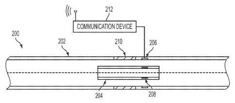
of the
wellbores. To obtain an angle of inclination to drill directional wells,
downhole drilling
motors can include adjustable housing assemblies. An adjustable housing
assembly
can allow the drill operator to change the inclination of a housing assembly
without
replacing the entire bent housing section. An amount of bend downhole of an
adjustable housing assembly can be challenging to obtain.
Brief Description of the Drawings
[0004] FIG. 1 is a cross-sectional view of one embodiment of a system
that
includes an adjustable motor assembly for which bend measurements can be
determined using magnetometers.
CA 02924358 2016-03-14
WO 2015/102599 PCT/US2013/078420
2
[0005] FIG. 2A is a cross-sectional side view of one embodiment of an
assembly for determining bend measurements of an adjustable motor assembly
using magnetometers.
[0006] FIG. 2B is a cross-sectional end view of the embodiment in FIG. 2A
in
which there is no bend in the adjustable motor assembly according to one
example.
[0007] FIG. 20 is a cross-sectional end view of the embodiment in FIG. 2A
in
which there is a bend in the adjustable motor assembly according to one
example.
[0008] FIG. 3A is a cross-sectional side view of another embodiment of an
assembly for determining bend measurements of an adjustable motor assembly
using magnetometers in which there is no bend in the adjustable motor assembly
according to one example.
[0009] FIG. 3B is a cross-sectional side view of the embodiment in FIG.
3A in
which there is a bend in the adjustable motor assembly according to one
example.
[0010] FIG. 4A is a cross-sectional side view of another embodiment of an
assembly for determining bend measurements of an adjustable motor assembly
using magnetometers in which there is no bend in the adjustable motor assembly
according to one example.
[0011] FIG. 4B is a cross-sectional side view of the embodiment in FIG.
4A in
which there is a bend in the adjustable motor assembly according to one
example.
[0012] FIG. 40 is a cross-sectional end view of the embodiment in FIG. 4A
in
which there is no bend in the adjustable motor assembly according to one
example.
[0013] FIG. 5 is an example of a flow chart of a process for determining
bend
measurements of an adjustable motor assembly using magnetometers according to
one embodiment.
CA 02924358 2016-03-14
WO 2015/102599 PCT/US2013/078420
3
[0014]
FIG. 6 is a block diagram depicting an example of a computing device
for determining bend measurements of an adjustable motor assembly using
magnetometers.
Detailed Description
[0015]
Certain aspects and features of the present disclosure are directed to
determining bend measurements of adjustable motor assemblies using
magnetometers. The adjustable motor assembly can include a first motor housing
assembly member. The adjustable motor assembly can further include a second
motor housing assembly member. The second motor housing assembly member
can be coupled to the first motor housing assembly member so that the first
motor
housing assembly member can bend relative to the second motor housing assembly
member at a bend location in a wellbore. The adjustable motor assembly can
also
include a magnet and a sensor. In one embodiment, the magnet can be positioned
on the first motor housing assembly member so a sensor can detect the strength
of
the magnetic field emitted by the magnet. The magnet can be an electromagnet.
In
such an embodiment, the sensor can be magnetically coupleable with the magnet
and positioned on the second motor housing assembly member to detect the
strength of the magnetic field emitted by the magnet. The
sensor is a
magnetometer.
[0016] In
another embodiment, the adjustable motor assembly can further
include a third motor assembly member located inside the first or second motor
housing assembly members. The third motor assembly member can be a mandrel.
In one such embodiment, a magnet can be positioned on the third motor assembly
member so that the sensor can detect the strength of the magnetic field
emitted by
CA 02924358 2016-03-14
WO 2015/102599 PCT/US2013/078420
4
the magnet. The sensor can be positioned on the first or second motor housing
assembly members for detecting the strength of the magnetic field emitted by
the
magnet. In another embodiment, the magnet can be positioned on the first or
second motor housing assembly members. The sensor can be positioned on the
third motor assembly member to detect the strength of the magnetic field
emitted by
the magnet. In some embodiments, the third motor assembly member can rotate
around a rotation axis.
[0017] The distance between the sensor and the magnet can change as the
first motor housing assembly member bends relative to the second motor housing
assembly member. The sensor measurement of the strength of the magnetic field
emitted by the magnet can change as the distance changes. The changed sensor
measurement can be used to determine the amount of bend or bend direction of
the
first motor assembly housing member relative to the second motor assembly
housing
member.
[0018] In one example, an adjustable motor assembly can be a part of a
bottom hole drilling assembly deployed in a wellbore. The first and second
motor
housing assembly members can be drill motor housing assembly members of the
adjustable motor assembly. A drill operator can cause the adjustable motor
assembly to bend at a bend location in the wellbore such that a first motor
assembly
housing member bends relative to a second motor assembly housing member at the
bend location. As the first housing member bends relative to the second
housing
member, the distance between a magnet and a sensor can change. The strength
measurements from the sensor can be used to determine the amount of bend and,
in
some embodiments, the bend direction of the first motor housing member
relative to
the second motor housing member. Assemblies according to some embodiments
CA 02924358 2016-03-14
WO 2015/102599 PCT/US2013/078420
can allow the drill operator to confirm that the adjustable motor assembly is
functioning properly or predict how the bottom hole assembly will perform in a
formation.
[0019] These illustrative examples are given to introduce the reader to
the
general subject matter discussed here and are not intended to limit the scope
of the
disclosed concepts. The following sections describe various additional
features and
examples with reference to the drawings in which like numerals indicate like
elements, and directional descriptions are used to describe the illustrative
aspects
but, like the illustrative aspects, should not be used to limit the present
disclosure.
[0020] FIG. 1 is a cross-sectional view side of one embodiment of a
system
100 that includes an adjustable motor assembly 122 for which bend measurements
can be determined using magnetometers. In this example, the system 100 is a
well
system (e.g., an oil or gas well for extracting fluids from a subterranean
formation).
The system 100 can include a wellbore 112 drilled out of a formation 120 from
a
surface 114. A drill string 124, which can contain a bottom hole assembly for
drilling,
can be located in the wellbore 112. The bottom hole assembly can include an
upper
connection 110, a power section 108, and a drill bit 102. The power section
108 can
include a motor assembly 122 with an adjustable housing 104 that can bend at a
bend location 106.
[0021] The system 100 can also include a computing device 116 for
receiving
bend measurements or direction measurements. The computing device 116 can be
positioned at the wellbore surface 114, below ground, or offsite. The
computing
device 116 can include a processor interfaced with other hardware via a bus. A
memory, which can include any suitable tangible (and non-transitory) computer-
readable medium such as RAM, ROM, EEPROM, or the like, can embody program
CA 02924358 2016-03-14
WO 2015/102599 PCT/US2013/078420
6
components that configure operation of the computing device 116. In this
example,
the computing device 116 can further include input/output interface components
and
additional storage.
[0022] The
computing device 116 can receive bend measurements or
direction measurements via a communication device 118. The communication
device 118 can represent one or more of any components that facilitate a
network
connection. In this example, the communication device 118 is wireless and can
include wireless interfaces such as IEEE 802.11, Bluetooth, or radio
interfaces for
accessing cellular telephone networks (e.g., transceiver/antenna for accessing
a
CDMA, GSM, UMTS, or other mobile communications network). In
other
embodiments, the communication device 118 can be wired and can include
interfaces such as Ethernet, USB, or IEEE 1394.
[0023]
FIG. 2A is a cross-sectional side view of one embodiment of an
assembly for determining bend measurements of an adjustable motor assembly 200
using magnetometers. The adjustable motor assembly 200 can include a housing
202 that can bend via an adjustable ring 210. The adjustable motor assembly
200
can include a mandrel 204 inside the housing 202. The adjustable motor
assembly
200 can further include a magnet 208 positioned on the mandrel such that the
magnetic field emitted by the magnet 208 can be detected by a sensor 206. The
sensor 206 can be positioned on a housing 202 so that the sensor 206 can
detect
the magnetic field emitted by the magnet 208. As the housing 202 bends, the
distance between the magnet 208 and the sensor 206 can change. As the distance
changes, the strength of the magnetic field measured by the sensor 206 can
change.
The change in the magnetic field measured by sensor 206 can be used to
determine
an amount of bend or bend direction of the adjustable motor assembly 200.
CA 02924358 2016-03-14
WO 2015/102599 PCT/US2013/078420
7
[0024] In
other embodiments, the magnet 208 can be positioned on a
rotating shaft, rather than mandrel 204, such that the magnetic field emitted
by the
magnet 208 can be detected by the sensor 206. The rotating shaft can rotate
around a rotational axis. A change in the magnetic field detected by the
sensor 206
can indicate an amount of rotation by the rotating shaft.
[0025] The
sensor 206 is a magnetometer. A magnetometer according to
some embodiments can measure the total strength of the magnetic field to which
the
magnetometer is subjected, but not the direction of the magnetic field.
Examples of
this type of magnetometer include a proton procession magnetometer, an
Overhauser effect magnetometer, and a caesium vapor magnetometer. A
magnetometer according to other embodiments can measure both the total
strength
of the magnetic field and the direction of the magnetic field relative to the
spatial
orientation of the magnetometer. Examples of this type of magnetometer include
a
Hall effect sensor, a magnetoresistive device, a fluxgate magnetometer, a
superconducting quantum interference device, and a spin-exchange relaxation-
free
atomic magnetometer. In some embodiments, the sensor 206 can include a
communication device 212 for communicating with a computing device, e.g. the
computing device 116 depicted in FIG. 1.
[0026] In
some embodiments, multiple sensors and multiple magnets can be
used in the configuration shown in FIG. 2A. For example, as shown in FIG. 2B,
three magnets 208a-c and three sensors 206a-c can be equally spaced around the
circumference of the mandrel 204 and the housing 202, respectively, such that
each
sensor 206a-c can detect a magnetic field from a particular magnet 208a-c. In
other
embodiments, the three magnets 208a-c can be equally spaced around the
circumference of the housing 202 and the three sensors 206a-c can be equally
CA 02924358 2016-03-14
WO 2015/102599 PCT/US2013/078420
8
spaced around the circumference of the mandrel 204, such that each sensor 206a-
c
can detect a magnetic field from a particular magnet 208a-c. Magnetic field
measurements from each sensor 206a-c can be used to determine a relative bend
direction and bend amount of the first motor housing assembly member to the
second motor housing assembly member. When there is no bend, the distance of
each magnet 208a-c to its sensor 206a-c can be roughly equal and,
consequently,
sensor measurements can be roughly equal.
[0027] FIG. 20 is a cross-sectional end view of the embodiment in FIG. 2A
showing a bend in the adjustable motor assembly 200 according to one example.
When there is a bend in the adjustable motor assembly 200, the distance of
each
magnet 208a-c to its sensor 206a-c can change. The amount of change can be
based on the amount of bend or bend direction of the first motor housing
assembly
member relative to the second motor housing assembly member. As the distance
of
each magnet 208a-c to its sensor 206a-c changes, so too can the magnetic field
measurements by the sensors 206a-c. The changed magnetic field measurements
can be used to determine the bend direction and bend amount of the first motor
housing assembly member relative to the second motor housing assembly member.
[0028] In some embodiments, the computing device 116 depicted in FIG. 1
can determine one or both of a bend direction and a bend amount based on
changes
in magnetic fields measured by one or more of the sensors 206a-c. For example,
the computing device 116 can determine a first set of magnetic field
measurements
at the respective sensors 206a-c. The computing device 116 can associate the
first
set of magnetic field measurements with a first bend direction or bend amount
(e.g.,
an absence of bending in any direction for an un-bent motor assembly 122), for
example, associating the first set of magnetic field measurements with a first
vector.
CA 02924358 2016-03-14
WO 2015/102599 PCT/US2013/078420
9
Further, the computing device 116 can determine a second set of magnetic field
measurements at the respective sensors 206a-c based on a bending of the motor
assembly 122. The computing device 116 can associate the second set of
magnetic
field measurements with a second bend direction or bend amount, for example,
by
associating the second set of magnetic field measurements with a second
vector. In
some embodiments, computing device 116 can determine a change in the bend
angle or direction by comparing the first vector with the second vector, for
example,
by comparing the direction cosines of the first and second vectors.
[0029] In
other embodiments, the computing device 116 can determine a first
or second bend direction or bend amount by other means. For example, an
increase
in the magnetic field measurement at the sensor 206a and a decrease in the
magnetic field measurements at the respective sensors 206b, 206c can indicate
a
bend in the direction of the sensor 206a. The computing device 116 can
correlate a
bend amount with one or more of an amount by which the magnetic field
measurement at the sensor 206a increases and the amounts by which the magnetic
field measurements at the respective sensors 206b, 206c decrease.
[0030] In
additional or alternative embodiments, a computing device 116 can
determine an amount of rotation based on changes in magnetic fields measured
by
one or more of the sensors 206a-c. For example, the computing device 116 can
determine a first set of magnetic field measurements at the respective sensors
206a-
c. The computing device 116 can associate the first set of magnetic field
measurements with a first angular orientation of a rotating shaft to which the
magnets 208a-c may be attached. The computing device 116 can determine a
second set of magnetic field measurements at the respective sensors 206a-c
based
on a rotation of the shaft. For
example, an increase in the magnetic field
CA 02924358 2016-03-14
WO 2015/102599 PCT/US2013/078420
measurement at the sensor 206a and a decrease in the magnetic field
measurements at the respective sensors 206b, 206c can indicate a rotation
toward
the sensor 206a and away from the sensors 206b, 206c. The computing device 116
can correlate an amount of rotation with one or more of an amount by which the
magnetic field measurement at the sensor 206a increases and the amounts by
which
the magnetic field measurements at the respective sensors 206b, 206c decrease.
[0031] FIG. 3A is a cross-sectional side view of another embodiment of an
assembly 300 for determining bend measurements of an adjustable motor assembly
300 using magnetometers 302 in which there is no bend in the adjustable motor
assembly according to one example. The adjustable motor assembly 300 can
include a bendable housing 306. A sensor 302 can be positioned on a first side
of a
bend location 310 and a magnet 304 can be positioned on a second side of the
bend
location 310. In one embodiment, the magnet 304 and the sensor 302 are
equidistant from the bend location 310. In another embodiment, the magnet 304
can
be on the outside of the bendable housing 306 and the bendable housing 306 can
be
magnetically penetrable. The magnet 304 can include an electromagnet and an
associated power source 308.
[0032] In some embodiments, a multitude of magnets 304 can be positioned
on the first side of bend location 310 and a multitude of sensors 302 can be
positioned on a second side of bend location 310. In one such embodiment, the
multitude of magnets 304 can be equidistant around the circumference of the
bendable housing 306 on the first side of the bend location and the multitude
of
sensors 302 can be equidistant around the circumference of the bendable
housing
306 on the second side of the bend location.
CA 02924358 2016-03-14
WO 2015/102599 PCT/US2013/078420
11
[0033] When there is no bend in the housing 306, the distance of a magnet
304 to a sensor 302 can be at a maximum. If housing 306 bends, as shown in
FIG.
3B, the distance between the magnet 304 and sensor 302 can decrease, causing a
magnetic field strength measurement at the sensor 302 to change. The changed
magnetic field strength measured by the sensor 302 can be used to determine
the
bend direction and bend amount in the adjustable motor assembly 300.
[0034] FIG. 4A is a cross-sectional side view of another embodiment of an
assembly 400 for determining bend measurements of an adjustable motor assembly
400 using magnetometers 406a, 406b. The adjustable motor assembly 400 can
include a housing 402 that can bend via an adjustable ring 410. In some
embodiments, the adjustable motor assembly 400 can include a mandrel inside
the
housing 402. The adjustable motor assembly 400 can further include a first
magnet
408a positioned on the housing 402 at a first side of a bend location 414. The
adjustable motor assembly 400 can further include a second magnet 408c
positioned
on the housing 402 at a second side of the bend location 414. A sensor 406a
can be
positioned on a housing 402 for detecting the combined magnetic field emitted
by the
magnets 408a, 408c. In some embodiments, the combined magnetic field of two
cylindrical magnets can be determined by the following equation:
[EgA2 (1? Rns 1 1 2
F = 1_7
ritoL2 Lx- (x 2Ly2 L)2
Where L is the length of the magnets, B is the magnetic flux, x is the
distance
between the magnets, and F is the resulting force between the two magnets.
Bending the housing 402 can change the distance between the first magnet 408a
and the second magnet 408c, causing the combined magnetic field between the
two
magnets to change. Changing the combined magnetic field can alter the strength
of
CA 02924358 2016-03-14
WO 2015/102599 PCT/US2013/078420
12
the magnetic field measured by the sensor 406a. The change in magnetic field
measured by sensor 406a can be used to determine an amount of bend in the
housing 402.
[0035] A third magnet 408b, a fourth magnet 408d, and a second sensor
406b
can be positioned on the opposite side of the housing 402 from the first
magnet
408a, second magnet 408c, and first sensor 406a. The third magnet 408b can be
positioned on the housing 402 on a first side of a bend location 414. The
fourth
magnet 408d can be positioned on the housing 402 on a second side of the bend
location 414. The second sensor 406b can be positioned on the housing 402 for
detecting the combined magnetic field emitted by the magnets 408b, 408d.
Bending
the housing 402 can change the distance between the third magnet 408b and the
fourth magnet 408d, altering the combined magnetic field. Altering the
combined
magnetic field can change the strength of the magnetic field measured by the
second sensor 406b. The change in magnetic field measured by sensor 406b can
be used to determine an amount of bend in the housing 402. Further, the
changes in
sensors 406a, 406b can be combined to determine a bend direction.
[0036] For example, as depicted in FIG. 4B, bending the motor assembly
400
can increase the distance between the first magnet 408a and the second magnet
408c, and decrease the distance between the third magnet 408b and the fourth
magnet 408d. The increased distance between magnet 408a and magnet 408c can
cause a decrease in the combined magnetic field measured by the sensor 406a.
The decreased distance between magnet 408b and magnet 408d can cause an
increase in the combined magnetic field measured by the sensor 406b. The
changed magnetic field measurements can be used to determine a bend amount or
bend direction.
CA 02924358 2016-03-14
WO 2015/102599 PCT/US2013/078420
13
[0037] FIG. 40 is a cross-sectional end view of the embodiment in FIG. 4A
in
which there is no bend in the adjustable motor assembly according to one
example.
In this example, a first set of magnets 408c-e are positioned on the housing
402 on a
second side of a bend location 414. Sensors are positioned on the housing 402
behind the first set of magnets 408c-e. Further, a second set of magnets are
positioned on the housing 402 and behind the sensors 406a-c on the first side
of a
bend location 414. When there is no bend in the adjustable motor assembly 400,
the
distance of each first magnet 408c-e to its associated second magnet is
relatively
equal. The sensors can measure the combined magnetic field emitted by each of
the respective magnet pairs. A computing device, such as the computing device
116
of FIG. 1, can associate the set of magnetic field measurements with a first
bend
direction or bend amount, for example, by associating the magnetic field
measurements with a first vector.
[0038] When there is a bend in the adjustable motor assembly 400, the
distance of each first magnets 408c-e to associated second magnet can change.
For example, bending the motor assembly 400 as shown in FIG. 4B can increase
the
distance between magnet 408c and its associated second magnet and decrease the
distance between magnet 408d and its associated second magnet. The increased
distance between magnet 408c and its associated magnet and can cause a
decrease in the combined magnetic field measured by the sensor positioned
between them. The decreased distance between magnet 408d and its associated
magnet can cause an increase in the combined magnetic field measured by the
sensor positioned between them. The changed magnetic field measurements can
be used to determine a second vector, which can be used to determine a bend
CA 02924358 2016-03-14
WO 2015/102599 PCT/US2013/078420
14
amount or bend direction. Further, in some embodiments, the second vector can
be
compared to the first vector to determine a change in bend amount or bend
direction.
[0039] As
another example, bending the motor assembly 400 horizontally to
the right can increase the distance between magnet 408c and its associated
magnet
and decrease the distance between magnet 408d and its associated magnet. The
distance between magnet 408e and its associated magnet should remain
relatively
the same. The changed distances can cause a change in the combined magnetic
fields measured by the sensors. The changed magnetic field measurements can be
used to determine a vector, which can be used to determine a bend amount or
bend
direction.
[0040]
FIG. 5 is an example of a flow chart of a process 500 for determining
bend measurements of an adjustable motor assembly using magnetometers
according to one embodiment.
[0041] In
block 502, a magnet emits a magnetic field that can be detected by a
sensor that is a magnetometer. The magnet is positioned so that the magnetic
field
emitted by the magnet is strong enough that it can be detected by the sensor.
The
magnet can be an electromagnet coupled to a power source. In one embodiment,
the sensor can filter out background magnetic fields generated by sources
other than
the magnet. In some embodiments, the sensor can detect both the magnitude and
direction of the magnetic field emitted by the magnet.
Further, in some
embodiments, components of the adjustable motor assembly can be magnetically
penetrable.
[0042] In
some embodiments, the magnet can be positioned on a first motor
housing assembly member so the magnetic field emitted by the magnet can be
detected by the sensor. The sensor can be positioned on a second motor housing
CA 02924358 2016-03-14
WO 2015/102599 PCT/US2013/078420
assembly member for detecting the strength of the magnetic field emitted by
the
magnet. In other embodiments, the magnet can be positioned on a third motor
assembly member inside the first or second motor housing assembly member, like
a
mandrel, so the magnetic field emitted by the magnet can be detected by the
sensor.
The sensor can be positioned on the first or second motor housing assembly
members for detecting the strength of the magnetic field emitted by the
magnet. In
another embodiment, the sensor can be positioned on a third motor assembly
member inside the first or second motor housing assembly member, like a
mandrel,
for detecting the magnetic field emitted by the magnet. The magnet can be
positioned on the first or second motor housing assembly members so that the
sensor can detect the strength of the magnetic field emitted by the magnet.
[0043] In block 504, the sensor detects a strength of the magnetic field
emitted by the magnet. The sensor is a magnetometer. The strength of the
magnetic field as detected by the sensor is a function of both the strength of
the
magnet and the distance between the magnet and the sensor. The detected
magnetic field strength can decrease with increasing distance between the
magnet
and the sensor. In some embodiments, the sensor can further detect the
direction of
the magnetic field emitted by the magnet. The magnetic field strength
detection can
be used as a baseline measurement against which subsequent magnetic field
detections can be compared to determine an amount of bend or bend direction of
an
adjustable motor assembly (such as, but not limited to, the motor assemblies
200,
300, or 400).
[0044] In block 506, the strength of the magnetic field detected is
communicated, by a communication device 212, to a computing device 116. The
communication can further include the direction of the magnetic field emitted
by the
CA 02924358 2016-03-14
WO 2015/102599 PCT/US2013/078420
16
magnet. The computing device 116 can be located at any suitable location
(e.g., at
the surface of the wellbore, below ground, or offsite).
[0045] In block 508, a first motor housing assembly member bends relative
to
a second motor housing assembly member at a bend location in a wellbore 112.
In
one such embodiment, a drill operator can cause the first motor housing
assembly
member to bend relative to the second motor housing assembly member in order
to
navigate around a bend in the formation of the wellbore 112. In some
embodiments,
the first motor housing assembly can bend relative to the second motor housing
assembly member automatically in response to encountering a bend in the
formation
of the wellbore 112. In another embodiment, the drill operator can cause the
first
motor housing assembly member to bend relative to the second motor housing
assembly member to drill along a designated drilling trajectory. As the first
motor
housing assembly member bends relative to the second motor assembly housing
member, the distance between the sensor and the magnet can change. As the
distance changes, the strength of the magnetic field emitted by the magnet as
detected by the sensor can change.
[0046] In block 510, the sensor detects a subsequent parameter of the
magnetic field. The sensor can detect a magnetic field strength or direction
that has
changed from the baseline magnetic field strength detection.
[0047] In block 512, the sensor communicates, by a communication device
212, to a computing device 116 the subsequent parameter of the magnetic field
detected.
[0048] In block 514, the amount of bend and a bend direction of the first
motor
housing assembly member relative to the second motor housing assembly member
is determined. In some embodiments, the bend direction and bend amount can be
CA 02924358 2016-03-14
WO 2015/102599 PCT/US2013/078420
17
determined based on a comparison of the baseline magnetic field strength
detected
to the subsequent magnetic field parameter detected. The amount of change in
the
sensor measurements can be indicative of the amount of bend and bend direction
of
the first motor housing assembly member relative to a second motor housing
assembly member. In one embodiment, the sensor can determine the amount of
bend and a bend direction of the first motor housing assembly member relative
to the
second motor housing assembly member. In other embodiments, the computing
device 116 can determine the amount of bend and a bend direction of the first
motor
housing assembly member relative to the second motor housing assembly member.
[0049] In
some embodiments, the computing device 116 can receive the
amount of bend and bend direction via a communication device 212 and compare
it
with a designated drilling trajectory. Should the amount of bend and bend
direction
received by the computing device 116 need to be altered to conform with the
designated drilling trajectory, the computing device 116 can cause the amount
of
bend or bend direction of the second motor housing assembly member relative to
the
first motor housing assembly member to change.
[0050]
FIG. 6 is a block diagram depicting an example of a computing device
116 for determining bend measurements of an adjustable motor assembly using
magnetometers. The computing device 116 includes a processing device 602, a
memory device 604, and a bus 606.
[0051] The
processing device 602 can execute one or more operations
determining bend measurements of an adjustable motor assembly using
magnetometers. The processing device 602 can execute instructions 608 stored
in
the memory device 604 to perform the operations. The processing device 602 can
include one processing device or multiple processing devices. Non-
limiting
CA 02924358 2016-03-14
WO 2015/102599 PCT/US2013/078420
18
examples of the processing device 602 include a Field-Programmable Gate Array
("FPGA"), an application-specific integrated circuit ("ASIC"), a
microprocessor, etc.
[0052] The processing device 602 can be communicatively coupled to the
memory device 604 via the bus 606. The non-volatile memory device 604 may
include any type of memory device that retains stored information when powered
off.
Non-limiting examples of the memory device 604 include electrically erasable
programmable read-only memory ("ROM"), flash memory, or any other type of non-
volatile memory. In some aspects, at least some of the memory device 604 can
include a medium from which the processing device 602 can read instructions. A
computer-readable medium can include electronic, optical, magnetic, or other
storage devices capable of providing the processing device 602 with computer-
readable instructions or other program code. Non-limiting examples of a
computer-
readable medium include (but are not limited to) magnetic disk(s), memory
chip(s),
ROM, random-access memory ("RAM"), an ASIC, a configured processor, optical
storage, and/or any other medium from which a computer processor can read
instructions. The instructions may include processor-specific instructions
generated
by a compiler and/or an interpreter from code written in any suitable computer-
programming language, including, for example, C, C++, C#, etc.
[0053] In some aspects, an assembly for determining bend measurements of
an adjustable motor assembly using magnetometers is provided according to one
or
more of the following examples.
[0054] Example #1: An assembly for determining bend measurements of an
adjustable motor assembly using magnetometers can include a first motor
housing
assembly member. The assembly can also include a second motor housing
assembly member, a magnet, and a sensor. The second motor housing assembly
CA 02924358 2016-03-14
WO 2015/102599 PCT/US2013/078420
19
member can be coupled to the first motor housing assembly member and bendable
relative to the first motor housing assembly member at a bend location in a
wellbore.
The magnet can be positioned such that the sensor can detect the strength of
the
magnetic field emitted by the magnet. The sensor can be magnetically
coupleable
with the magnet and positioned to determine an amount of bend of the second
motor
housing assembly member relative to the first motor housing assembly member by
detecting a strength of the magnetic field emitted by the magnet.
[0055] Example #2: The assembly of Example #1 may feature
magnetometers further positioned to determine a bend direction.
[0056] Example #3: The assembly of any of Examples #1-2 may feature a
communication device communicatively coupled with a computing device.
[0057] Example #4: The assembly of any of Examples #1-3 may feature the
first motor assembly housing member or the second motor assembly housing
member including a motor operatively coupleable to a drill bit.
[0058] Example #5: The assembly of any of Examples #1-4 may feature a
magnet positioned on a first side of the bend location and the sensor
positioned on a
second side of the bend location.
[0059] Example #6: The assembly of any of Examples #1-5 may feature the
magnet positioned on the exterior of the first motor assembly housing member.
[0060] Example #7: The assembly of any of Examples #1-6 may feature the
first motor assembly housing member being magnetically penetrable.
[0061] Example #8: The assembly of any of Examples #1-7 may feature the
sensor positioned on the exterior of the second motor assembly housing member.
[0062] Example #9: The assembly of any of Examples #1-8 may feature the
magnet and the sensor located equidistant from the bend location.
CA 02924358 2016-03-14
WO 2015/102599 PCT/US2013/078420
[0063] Example #10: The assembly of any of Examples #1-9 may feature the
magnet being included in a multitude of magnets that are positioned on the
first side
of the bend location.
[0064] Example #11: The assembly of Example #10 may feature the
multitude of magnets equidistantly spaced around the circumference of the
first
motor housing assembly member.
[0065] Example #12: The assembly of any of Examples #10-11 may feature a
sensor being included in a multitude of sensors that are positioned on the
second
side of the bend location and magnetically coupleable with the multitude of
magnets.
[0066] Example #13: The assembly of Example #12 may feature the
multitude of sensors equidistantly spaced around the circumference of the
second
motor housing assembly member.
[0067] Example #14: The assembly of any of Examples #1-5, 7, 9-10, and 12
may feature a third motor assembly member inside the first motor housing
assembly
member or the second motor housing assembly member.
[0068] Example #15: The assembly of Example #14 may feature the magnet
positioned on the third motor assembly member.
[0069] Example #16: The assembly of Example #15 may feature the magnet
being included in a multitude of magnets that are positioned on the third
motor
assembly member.
[0070] Example #17: The assembly of Example #16 may feature the
multitude of magnets equidistantly spaced around the circumference of the
third
motor assembly member.
[0071] Example #18: The assembly of any of Examples #14-17 may feature
the third motor assembly member being rotatable around a rotation axis.
CA 02924358 2016-03-14
WO 2015/102599 PCT/US2013/078420
21
[0072] Example #19: A method for determining bend measurements of an
adjustable motor assembly using magnetometers can include emitting a magnetic
field from a magnet. The sensor can detect the strength of the magnetic field.
The
sensor can communicate, by a communication device, to a computing device the
strength of the magnetic field detected. A first motor housing assembly member
can
bend relative to a second motor housing assembly member at a bend location in
a
wellbore. The sensor can detect a subsequent parameter of the magnetic field
emitted by the magnet. The sensor can communicate, by a communication device,
to a computing device the subsequent parameter of the magnetic field detected.
Finally, the assembly can determine an amount of bend or bend direction of the
second motor housing assembly member relative to the first motor housing
assembly
member based on the strength of the magnetic field emitted by the magnet.
[0073] Example #20: The method of Example #19 may feature determining
an amount of bend second motor housing assembly member relative to the first
motor housing assembly member by associating the strength of the magnetic
field
detected by the sensor with a first bend amount. The computing device can
associate the subsequent parameter of the magnetic field detected by the
sensor
with a second bend amount. Further, the computing device can determine the
difference between the first bend amount and the second bend amount.
[0074] Example #21: The method of any of Examples #19-20 may feature
determining a bend direction of the second motor housing assembly member
relative
to the first motor housing assembly member by associating the strength of the
magnetic field detected by the sensor with a first bend direction. The
computing
device can associate the subsequent parameter of the magnetic field detected
by the
CA 02924358 2016-03-14
WO 2015/102599 PCT/US2013/078420
22
sensor with a second bend direction. Finally, the computing device can
determine
the difference between the first bend direction and the second bend direction.
[0075] Example #22: The method of any of Examples #19-21 may feature
determining if the bend direction and bend amount should be altered to conform
with
a designated drilling trajectory. Further, the method may feature causing the
amount
of bend or bend direction of the second motor housing assembly member relative
to
the first motor housing assembly member to change.
[0076] Example #23: A
computing device for determining bend
measurements of an adjustable motor assembly using magnetometers can include a
processing device and a memory. The memory can include instructions executable
by the processing device. The instructions can include receiving a strength of
a
magnetic field detected by a sensor, and receiving a subsequent parameter of
the
magnetic field detected by the sensor.
Further, the instructions can include
determining an amount of bend or bend direction of a second motor housing
assembly member relative to a first motor housing assembly member based on the
strength of the magnetic field detected by the sensor.
[0077] Example #24: The computing device of Example #23 may feature
instructions for associating the strength of the magnetic field detected by
the sensor
with a first bend amount and associating the subsequent parameter of the
magnetic
field detected by the sensor with a second bend amount. The computing device
may
further feature instructions for determining the difference between the first
bend
amount and the second bend amount.
[0078] Example #25: The computing device of any of Examples #23-24 may
feature instructions for associating the strength of the magnetic field
detected by the
sensor with a first bend direction. The computing device may feature
instructions for
CA 02924358 2016-03-14
WO 2015/102599 PCT/US2013/078420
23
associating the subsequent parameter of the magnetic field detected by the
sensor
with a second bend direction. Finally, the computing device may feature
instructions
for determining the difference between the first bend direction and the second
bend
direction.
[0079] Example #26: The computing device of any of Examples #23-25 may
feature instructions for determining if the amount of bend or bend direction
should be
altered to conform with a designated drilling trajectory and causing the
amount of
bend or bend direction of the second motor housing assembly member relative to
the
first motor housing assembly member to change.
[0080] The foregoing description of certain embodiments, including
illustrated
embodiments, has been presented only for the purpose of illustration and
description
and is not intended to be exhaustive or to limit the disclosure to the precise
forms
disclosed. Numerous modifications, adaptations, and uses thereof will be
apparent to
those skilled in the art without departing from the scope of the disclosure.