Language selection

Search

Patent 2962694 Summary

Third-party information liability

Some of the information on this Web page has been provided by external sources. The Government of Canada is not responsible for the accuracy, reliability or currency of the information supplied by external sources. Users wishing to rely upon this information should consult directly with the source of the information. Content provided by external sources is not subject to official languages, privacy and accessibility requirements.

Claims and Abstract availability

Any discrepancies in the text and image of the Claims and Abstract are due to differing posting times. Text of the Claims and Abstract are posted:

  • At the time the application is open to public inspection;
  • At the time of issue of the patent (grant).
(12) Patent: (11) CA 2962694
(54) English Title: LAYING AND PROTECTING CABLE INTO EXISTING COVERING SURFACES
(54) French Title: DEPOSE ET PROTECTION DE CABLE DANS DES SURFACES DE RECOUVREMENT EXISTANTES
Status: Granted
Bibliographic Data
(51) International Patent Classification (IPC):
  • E02F 5/08 (2006.01)
  • E02F 5/10 (2006.01)
  • F16L 1/032 (2006.01)
  • H02G 1/06 (2006.01)
  • H02G 9/02 (2006.01)
(72) Inventors :
  • MILLER, DANIEL PAUL (United States of America)
(73) Owners :
  • QUANTA ASSOCIATES, L.P. (United States of America)
(71) Applicants :
  • CERTUSVIEW TECHNOLOGIES, LLC (United States of America)
(74) Agent: RIDOUT & MAYBEE LLP
(74) Associate agent:
(45) Issued: 2019-01-15
(22) Filed Date: 2010-09-23
(41) Open to Public Inspection: 2011-03-31
Examination requested: 2017-03-29
Availability of licence: N/A
(25) Language of filing: English

Patent Cooperation Treaty (PCT): No

(30) Application Priority Data:
Application No. Country/Territory Date
61/244,954 United States of America 2009-09-23

Abstracts

English Abstract

To construct an underground cable line in-situ, cut and immediately evacuate a void in the existing covering surface. Next, lay or apply cable(s) into the void. Then, flow a non-shrinking composition into a portion of the void around the cable to fill a portion of the void. Upon rigidification the cable is encased in the void by the non-shrinking composition. Last, apply a topping material to the exposed surface of the composition in such volume as to fill any remaining portion of the void.


French Abstract

Construire une ligne de câble sous-terrain sur place, couper et immédiatement excaver un espace vide dans une surface de recouvrement existante. Puis, le câble est déposé ou posé dans lespace vide. Puis, une composition non rétrécissante est coulée dans une portion de lespace vide autour du câble pour remplir une portion de lespace vide. À la rigidification, le câble est enveloppé dans lespace vide par la composition non rétrécissante. En dernier, un matériau de recouvrement est appliqué sur la surface exposée de la composition en un volume tel à remplir toute portion restante de lespace vide.

Claims

Note: Claims are shown in the official language in which they were submitted.


CLAIMS:
1. A method for constructing an underground cable line in-situ through an
existing covering
surface disposed over a subsurface below the existing covering surface, the
existing covering
surface comprising a first material selected from a group consisting of
pavement, paving,
concrete, asphalt, blacktop, cobblestone and brick, and the subsurface
comprising a second
material different from the first material, the method comprising:
A) cutting the existing covering surface to create a void through the existing
covering
surface and into the second material of the subsurface below the existing
covering surface and
thereby creating a volume of debris, wherein the void has a depth greater than
the existing
covering surface and a width between 1.27 cm and 3.8 cm;
B) evacuating the volume of debris from at least the void;
C) laying a cable into the void;
D) flowing a non-shrinking composition into a portion of the void so as to
encase the
cable; and
E) after hardening of the non-shrinking composition, applying a topping
material to a
remaining portion of the void.
2. The method of claim 1, wherein evacuating the volume of debris from at
least the void
comprises:
vacuuming the volume of debris concurrently with cutting the existing covering
surface to
create the void through the existing covering surface and into the second
material of the
subsurface below the existing covering surface.
3. The method of claim 2, wherein vacuuming the volume of debris
concurrently with
cutting the existing covering surface to create the void through the existing
covering surface and
into the second material of the subsurface below the existing covering surface
comprises:
cooling a cutting blade used in cutting the existing covering surface to
create the void
through the existing covering surface and into the second material of the
subsurface below the
existing covering surface and;
capturing a stream of loose debris created by the cutting blade.
9

4. The method of claim 1, wherein flowing a non-shrinking composition into
a portion of the
void so as to encase the cable comprises:
pumping said non-shrinking composition into the void.
5. The method of claim 1, wherein flowing a non-shrinking composition into
a portion of the
void so as to encase the cable comprises:
pouring said non-shrinking composition into the void.
6. The method of claim 1, wherein after hardening of the non-shrinking
composition,
applying a topping material to a remaining portion of the void comprises:
allowing a period of time not to exceed twelve hours to pass for setting and
rigidifying of
said non-shrinking composition prior to applying the topping material.
7. The method of claim 1, wherein said non-shrinking composition is
substantially
impermeable upon drying.
8. The method of claim 7, wherein a hydraulic impermeability of the non-
shrinking
composition is less than 0.0000001 cm/s upon drying.
9. The method of claim 1, wherein the act of cutting the existing covering
surface to create
a void through the existing covering surface is carried out continuously in
one and only one
swath from a starting point to a finishing point, and wherein the length of
the swath is at least
45.72 meters.
10. The method of claim 1, wherein the act of cutting the existing covering
surface to create
a void through the existing covering surface comprises cutting the existing
covering surface
such that the width of the void is approximately 1.5 inches.
11. The method of claim 1, wherein the non-shrinking composition is
configured to shrink
less than one percent upon drying at ambient temperatures.

12. The method of claim 1, wherein the non-shrinking composition is
configured to begin to
rigidify within one hour of being flowed into the portion of the void.
13. The method of claim 1, wherein the non-shrinking composition is
flowable.
14. The method of claim 13, wherein the non-shrinking composition is
configured to be
viscid and have a viscosity that facilitates flowing.
15. The method of claim 1, wherein the non-shrinking composition is
selected from a group
consisting of a grout and a mortar substance.
16. The method of claim 1, wherein the non-shrinking composition is
configured to be non-
compressible.
17. The method of claim 1, wherein the non-shrinking composition is
configured to be non-
expanding.
18. The method of claim 1, wherein the topping material is configured to
adhere to the non-
shrinking composition.
19. The method of claim 1, wherein applying a topping material to a
remaining portion of the
void comprises:
heating the topping material to 177 degrees centigrade before applying the
topping
material.
20. The method of claim 1, wherein the topping material is selected from a
group consisting
of blacktop, asphalt, and bitumen.
21. The method of claim 1, wherein the topping material includes a mastic
material.
22. A method for constructing an underground cable line in-situ through an
existing covering
surface, the method comprising:
11

A) cutting the existing covering surface to create a void through the existing
covering
surface and thereby creating a volume of debris, wherein the void has a width
between 1.27 cm
and 3.8 cm;
B) evacuating the volume of debris from at least the void;
C) laying a cable into the void;
D) flowing a non-shrinking composition into a portion of the void so as to
encase the
cable; and
E) after hardening of the non-shrinking composition, applying a topping
material to a
remaining portion of the void,
wherein the act of cutting the existing covering surface to create a void
through the
existing covering surface comprises cutting the existing covering surface such
that the void has
a depth of approximately 12 inches.
23. A method for constructing an underground cable line in-situ through an
existing covering
surface, the method comprising:
A) cutting the existing covering surface to create a void through the existing
covering
surface and thereby creating a volume of debris;
B) evacuating the volume of debris from at least the void;
C) laying a cable into the void;
D) flowing a non-shrinking composition into a portion of the void so as to
encase the
cable; and
E) after hardening of the non-shrinking composition, applying a topping
material to a
remaining portion of the void,
wherein the act of cutting the existing covering surface to create a void
through the
existing covering surface comprises cutting the existing cutting surface such
that the void has a
depth of approximately 12 inches and a width of between approximately 0.5
inches and
approximately 1.25 inches.
24. The method of any one of claims 1 to 23, comprising performing A) and
B) concurrently,
evacuating substantially all of the volume of debris in a single pass, and
leaving the void and
surrounding area substantially free of the debris.
19

25. The method of any one of claims 1 to 24, substantially free from
diffusing, circling, or
recycling the debris back into the void.
26. The method of claim 25, wherein:
A) comprises using a cutting blade, or the cutting blade when dependent on
claim 3, to
perform the cutting;
the cutting blade is a circular blade; and
in A), the cutting comprises rotating the circular blade to move a cutting
edge of the
circular blade contacting the existing covering surface and the second
material away from the
void thereby removing the debris without diffusing, circling, or recycling the
debris back into the
void.
27. The method of claim 26, wherein:
in A), the cutting comprises rotating the circular blade to move the cutting
edge of the
circular blade upwardly where the cutting edge contacts the existing covering
surface, and to
move a lowermost point of the cutting edge away from the void.
28. The method of any one of claims 1 to 27, wherein A) comprises forming a
stream of
loose debris, or the stream of loose debris when dependent on claim 3,
travelling in a cutting
direction of the cutting.
29. The method of claim 28 when dependent on claim 3 or 26, wherein the
cutting direction
of the cutting is a direction of travel of the cutting blade.
30. The method of any one of claims 1 to 29, wherein:
B) comprises vacuuming the volume of debris concurrently with A) by suctioning
at a
suctioning location where the debris emerges from the void.
31. The method of claim 30 when dependent on claim 28 or 29, comprising
forming the
stream of loose debris at the suctioning location.
13

32. The method of claim 30 or 31, wherein A) is performed at a cutting
location, and the
suctioning location is in front of the cutting location relative to a cutting
direction of the cutting, or
the cutting direction when dependent on claim 28.
33. The method of claim 3, or any one of claims 24 to 32 when dependent on
claim 3,
wherein the cooling comprises moving a volume of air over the cutting blade.
34. The method of claim 33, when dependent on claim 2 or 30, wherein the
vacuuming
causes at least in part the moving of the volume of air over the cutting
blade.
14

Description

Note: Descriptions are shown in the official language in which they were submitted.


CA 2962694 201/-03-29
LAYING AND PROTECTING CABLE INTO EXISTING COVERING SURFACES
[0001] This application is a divisional application of Canadian patent
application
number 2,774,988, filed September 23, 2010.
[0002] (This paragraph intentionally left blank).
[0003] (This paragraph intentionally left blank).
[0004] (This paragraph intentionally left blank).
[0005] (This paragraph intentionally left blank).
1

CA 2962694 2017-03-29
BACKGROUND
[0006] Problems are encountered when attempting to lay the "last mile" of
underground cables such as, for example, a fiber optic cable or an electrical
cable.
The problem is accentuated in urban areas due to the dense build-out of the
surrounding area, traffic congestions, and on-going road repairs occurring in
urban
areas.
[0007] Such cables may or may not be enclosed in a pipe or a conduit
depending on customer needs. One or more cables may be enclosed in such a pipe

or conduit depending on customer needs.
[0008] Prior systems used for the construction of underground paths for the
insertion of underground cable were cumbersome. For example, operators had to
make multiple passes to cut a slot prior to adequate insertion of the cable.
SUMMARY
[0009] An efficient system and method .for laying the "last mile" of
underground cables creating minimal disruption to property owners or less
impact to
the neighborhood is needed.
[0010] The following steps are carried out in the system and method. First,
cut and immediately evacuate a void in the existing covering surface. Next,
lay or
apply cable(s) (cable, ducts and/or conduits) into the void (i.e.
underground). Then,
flow a non-shrinking composition into a portion of the void around the cable
to fill a
portion of the void. Upon rig idification the cable is encased in the void by
the non-
shrinking composition. Last, apply a topping material to the exposed surface
of the
composition in such volume as to fill any remaining portion of the void. This
seals
the void now filled with an underground cable line as encased by the
composition.
2

CA 2962694 2017-03-29
BRIEF DESCRIPTION OF THE SEVERAL VIEWS OF THE DRAWINGS
[0011]
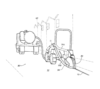
Fig. 1 is an elevation view of a cutting and evacuating machine making a
channel
through the covering surface in a neighborhood.
Fig. 2 is an elevation view of a grouting machine flowing grout into the
channel of the
covering surface within a neighborhood.
Fig. 3 is a sectional view of a channel through a covering surface filled with
cables,
grout and topping material.
Fig. 4 is a perspective view of one embodiment cutting and evacuating a void
in an
existing covering surface within a neighborhood.
Fig.5 is an elevation view of an embodiment of a portable cutting and
evacuating
machine with the blade of the cutter raised for inspection or transport.
Fig. 6 is a schematic view in section of an embodiment of a cutter and vacuum
system cutting and evacuating a void which is being cut into an existing
covering
surface.
DETAILED DESCRIPTION OF THE PREFERRED EMBODIMENT(S)
[0012] Referring to Fig. 1, an underground cable line 14 (Fig. 3) may be
constructed or installed into an existing covering surface 10. The covering
surface
is normally pre-existing and hence the challenge for construction of the
underground cable line 14. Such existing covering surface 10 could be, but is
not
limited to, pavement, paving, concrete, asphalt, blacktop, cobblestone, brick,
other
road base, grade or surface, or the like, or any combination of the foregoing
(e.g.
combination of asphalt laid over concrete).
[0013] To construct the underground cable line 14, operator(s) cut and
evacuate a void, channel or passage 12 into the existing covering surface 10
(having
sub-surface 11). It is advantageous to avoid making multiple passes (as done
in
prior systems) in order to cut the void 12. Therefore the void 12 is cut in
one and
3

CA 2962694 2017-03-29
only one pass or swath from, referring to Fig. 4, a first position or starting
point A to a second
position or finishing point B (which may, for example, be separated by
somekilometers or in
another example by 45.72 meters (150 feet), i.e., cut in one and onlyone pass
by a distance
more than a few centimeters). Some of the advantages to using this technique
include that
the base is not disturbed as with multiple passes; less time is consumed in
construction the
void; the void is constructed with a simpleuniform cut. Therefore the
technique of cutting the
void 12 in one and only one passis quite advantageous.
[0014] One embodiment of a machine 30 which may be used to cut and evacuate
in
one and only one swath includes, for example, a cutter 32 with a narrow
rotating blade 33 (Fig.
5) that will cut the existing covering surface 10 leaving a void 12 behind.
The machine 30 is
portable via, for example, wheels 38 (Fig. 5), and has an operator control
station 39. Operator
control station 39 (Fig. 5) includes a seat for the operator and a steering
wheel to turn the
machine 30. Each of the wheels 38 has an inner sidewall, an outer sidewall,
and a
circumferential area that contacts the covering surface 10. The
circumferential area of each of
the wheels 38 may include a grooved portion with a groove extending from the
outer sidewall to
the inner sidewall and may also include a portion free of grooves that is
substantially free of
tread. Outer sidewall and inner sidewall of wheels 38 may be substantially
planar.
[0015] Accompanying the cutter 32, the machine 30 also immediately cleans
or
evacuates the void 12 such as by blowing, vacuuming, and/or sweeping the void
12. In the
embodiment shown, a vacuum system 34 (e.g., including two evacuation ducts 50A
and 50B
and a Y-duct 51) accompanies the cutter 32 and is partially mounted to the
machine 30.
Preferably, but not limited to, the vacuum system 34 is in juxtaposition with
respect to the cutter
32 and is mounted upper-lower, respectively and in relation to the cutter 32
such that the step of
vacuuming occurs concurrent with the step of cutting the void 12. The vacuum
system 34 may
be connected to an independent portable vacuuming system 36 (Fig. 4) mounted
to a vehicle
and connected via a Y-duct 51.
[0016] In cutting the void 12 the action of the cutter 32 cuts and moves
material and/or
soil from the covering surface 10. This creates a stream or volume of debris
(designated by
arrows 18, Fig. 6) that generally has momentum from and travels in the
direction of the cutter 32
(at least initially). The vacuum system 34 in juxtaposition to the cutter 32
concurrently,
immediately and directly suctions the stream of debris 18 (preferably all or
at least substantially
4

CA 2962694 2017-03-29
all of the debris 18) through an inlet shroud 35 that includes one or more
vents 37 and which
overlaps the path of the stream of debris 18. This prevents the stream of
debris 18 (containing
cuttings, remnants, and/or excavated matter from the covering surface 10) from
diffusing,
circling with, and or recycling with the cutter 32 back into the void 12 and
from creating dust in
general. In the embodiment shown, the cutter 32 actually assists in moving the
stream of debris
around and into the cubic feet per second airflow suction of the vacuum system
34.
[0017] The blade 33 of the cutter 32 must have a width and diameter
sufficient to cut a
void 12 having a width and depth as follows. The width of the void 12 should
be narrow, i.e., as
narrow as possible to fit cable(s) or duct(s) 14 within the void 12. This
allows vehicles to
traverse the void 12 while the underground cable line 14 is being constructed
at the installation
site. One example of an acceptable width is 1.75 cm (11/16ths of an inch). For
purposes of
limiting the changing of the cutter 32 blade 33 it may be useful to offer
standard width
voids/channels 12, and normally the width of the void 12 will be selected from
either a range of
1.9 cm to 2.54 cm (0.75 in. - 1 in. wide), or a 3.175 cm (1.25 in.) wide void.
However, the width
of the void 12 is not limited to these certain standard ranges. The width of
the void 12 should be
less than about 3.8 cm (1.5 inches) in any case and preferably less than or
equal to 3.175 cm
(1.25 in.). It has been discovered that if the width of the void 12 is too
large, the asphalt will not
properly bridge making the disclosed technique ineffective. On the lower end,
voids 12 having a
width of 1.27 cm (0.5 in.) have been successfully implemented, but 1.27 cm
(0.5 in.) is not
necessarily limiting at the lower end.
[0018] The void 12 must be greater than 10.16 cm (four inches) deep into
the covering
surface 10. Presently the preferred depth of the void 12 is 30.48 cm (twelve
inches) deep. This
avoids the penetration of existing utility lines (and further thereby speeds
the permitting
process). Excessive depth of the channel may inhibit evacuation of the
cuttings or penetrate to
undesirable areas but otherwise the depth of void 12 is not limited.
[0019] As described above the evacuating step pertains to the removal from
the void
12 of any cuttings, etc. in the stream of debris 18 resulting from the cutting
of the existing
surface 10. Vacuuming simultaneously or instantaneously with the cutting of
the void 12 is
critical or quite advantageous to the effectiveness of the technology. By
suctioning while cutting
less dust is created, the action of the moving volume of air cools the cutting
blade 33, removes

CA 2962694 2017-03-29
materials that could create greater friction on the spinning blade 33, and
creates a void 12 free
of loose debris/cuttings. Vacuuming is one example of a procedure to be used
for evacuating.
[0020] One embodiment of a machine 30 which is acceptable for use for
carrying out the
steps of cutting and evacuating is commercially available from DITCHWITCHTm of
Perry,
Oklahoma, USA.
[0021] The cable(s) (cable, ducts and/or conduits) 14 must be laid or
applied into the
void 12. This may be performed by hand or machine (e.g. by machine 30). The
cable(s) 14 are
preferably placed into the bottom of the void 12. More than one cable 14 may
be placed in the
void 12. By way of example, ten to twelve small cables 14 each of which run to
individual
residences 40 may be placed in the void 12 together with another main cable
14a. Each cable
14 may contain, for example, one-hundred and forty-four fibers.
[0022] A composition 16 is flowed into the void 12 and over the cable(s)
14. Generally,
the composition must be a flowable composition 16 and non-shrinking upon
drying. The
composition 16 fills a bottom portion of the void 12 and bonds or encases the
cable(s) 14. The
composition 16 is preferably a plaster, grout, or mortar substance.
[0023] For flowing and encasing it is currently preferable to flow a
composition 16 in the
form of a grout 16a into the void 12 and over the cable(s) 14. To apply, the
operator will ensure
the duct 44 is held down into the void 12. Next, the grout 16a is pumped of
poured into the void
12 using, for example, a traditional grouting machine 42 having a pump 43 so
that it will flow
through the duct 44 and into the void 12. Preferably the operator will not
fill the void 12 with the
composition 16 up to the top level of the "covering surface" 10.
[0024] In describing the composition 16, by referring to it as "flowing" or
"flowable", this
means the composition 16 is viscid (i.e. has a sticky and fluid consistency)
yet having a viscosity
that does not prevent it from flowing into the void 12 on top of, around and
under (i.e.
surrounding) the cable(s) 14. The composition 16 flows under the cable(s) 14
and the cable(s)
14 could even experience some rise as the composition 16 flows around that
cable(s) 14
depending upon specific gravity of the cable(s) 14 relative to the composition
16. Due to the
flowability, no air-bubbles or spaces are created in the filled portion of the
void 12 below the
top surface 17 of the composition 16.
6

CA 2962694 2017-03-29
[0025] In describing the composition 16, by referring to it as "non-
shrinking",
this means the composition 16 is non-compressible, non-expandable, with no
contraction. By way of example, the composition 16 should shrink less than one

percent upon drying at ambient temperatures. As the composition 16 dries, no
air-
bubbles or spaces are created in the filled portion of the void 12 below the
top
surface 17 of the composition 16. There is no requirement to tamp the
composition
16.
[0026] The composition 16 undergoes rigidification or solidification upon
drying or setting. Upon drying, the cable(s) 14 are encased within the
composition
16 within the void 12.
[0027] The composition 16 should be fast drying. The composition 16 should
begin to rigidify within the first hour allowing the topping material 20 to be
applied
within approximately three to twelve hours after the composition 16 has been
pumped or poured into the void 12.
[0028] The dried, rigidified composition 16 is impermeable meaning its
hydraulic permeability is less than 0.0000001 cm/s. It has been discovered
that
groundwater does not negatively affect the integrity of the composition once
it is
rigidified within the void 12.
[0029] The currently preferred composition 16 is a grout 16a sold under the
TM
name SUPERGROUT, but other sufficiently flowable, non-shrinking materials may
be implemented into the respective embodiment(s) of the technology discussed
TM
herein. SUPERGROUT is commercially available via the owner of domain name
"supergroutproducts.com" or from MTsupergrout.com of Saginaw, Michigan. In
preparation, the grout 16a should be fluid when mixed with water. Blend, for
example, nineteen liters (five gallons) of potable water per seventy pound bag
of
TM
SUPERGROUT. The grout 16a sets in four hours, and sets as a rigid body. Such
grout 16a may be topped off with a topping material 20 within one hour of
pumping
or pouring.
7

CA 2962694 2017-03-29
[0030] The composition 16 and the remaining top portion of the void 12
should
be filled with a topping material 20 (e.g. blacktop) to cover and seal the
composition
16 and the void 12. The topping material 20 preferably adheres to the
composition
16. Preferably the topping material 20 is aesthetically invisible to the
untrained eye.
[0031] It may be preferable to add or blend aggregate into the topping
material
20 prior to its application. One having ordinary skill in the art knows how to
apply
such a topping material 20 which may, for example, be blacktop, asphalt or
bitumen
heated to 177 centigrade (350 Fahrenheit), and then applied or flowed into
the
remainder portion of the void 12.
[0032] A currently preferred topping material 20 (blacktop or asphalt) is a
mastic repair material commercially available from (with specifications as
provided
by) Deery American Corporation, such as that, for example, sold under the
brand
TM TM
name DEERY LEVEL & GO repair mastic or the like. Then, aggregate may be
mixed in prior to application.
[0033] An operator having ordinary skill in the art may desire to cut a
bend or
curve when cutting a void 12. The operator may for example achieve cornering
with
a 12.2 meter (forty ft.) bending radius, or may make two cuts intersecting at
ninety
degrees, for example, to form a corner.
[0034] The various embodiments disclosed may be used with dirt roads or a
soil surface as the technology is not necessarily limited to use on asphalt or
other
hard road surfaces.
[0035] After construction is completed and in the event that future road
repairs
or the like are needed, the applicable surface may be worked, planed, milled
and/or
removed without damage to the integrity of the cable(s) 14 and normally
without
damage to the integrity of the rigidified composition16.
8

Representative Drawing
A single figure which represents the drawing illustrating the invention.
Administrative Status

For a clearer understanding of the status of the application/patent presented on this page, the site Disclaimer , as well as the definitions for Patent , Administrative Status , Maintenance Fee  and Payment History  should be consulted.

Administrative Status

Title Date
Forecasted Issue Date 2019-01-15
(22) Filed 2010-09-23
(41) Open to Public Inspection 2011-03-31
Examination Requested 2017-03-29
(45) Issued 2019-01-15

Abandonment History

Abandonment Date Reason Reinstatement Date
2018-09-24 FAILURE TO PAY APPLICATION MAINTENANCE FEE 2018-12-05

Maintenance Fee

Last Payment of $263.14 was received on 2023-09-12


 Upcoming maintenance fee amounts

Description Date Amount
Next Payment if standard fee 2024-09-23 $347.00
Next Payment if small entity fee 2024-09-23 $125.00

Note : If the full payment has not been received on or before the date indicated, a further fee may be required which may be one of the following

  • the reinstatement fee;
  • the late payment fee; or
  • additional fee to reverse deemed expiry.

Patent fees are adjusted on the 1st of January every year. The amounts above are the current amounts if received by December 31 of the current year.
Please refer to the CIPO Patent Fees web page to see all current fee amounts.

Payment History

Fee Type Anniversary Year Due Date Amount Paid Paid Date
Request for Examination $800.00 2017-03-29
Registration of a document - section 124 $100.00 2017-03-29
Application Fee $400.00 2017-03-29
Maintenance Fee - Application - New Act 2 2012-09-24 $100.00 2017-03-29
Maintenance Fee - Application - New Act 3 2013-09-23 $100.00 2017-03-29
Maintenance Fee - Application - New Act 4 2014-09-23 $100.00 2017-03-29
Maintenance Fee - Application - New Act 5 2015-09-23 $200.00 2017-03-29
Maintenance Fee - Application - New Act 6 2016-09-23 $200.00 2017-03-29
Maintenance Fee - Application - New Act 7 2017-09-25 $200.00 2017-09-25
Reinstatement: Failure to Pay Application Maintenance Fees $200.00 2018-12-05
Final Fee $300.00 2018-12-05
Maintenance Fee - Application - New Act 8 2018-09-24 $200.00 2018-12-05
Registration of a document - section 124 $100.00 2019-05-16
Maintenance Fee - Patent - New Act 9 2019-09-23 $200.00 2019-09-20
Maintenance Fee - Patent - New Act 10 2020-09-23 $250.00 2020-09-18
Maintenance Fee - Patent - New Act 11 2021-09-23 $255.00 2021-09-20
Maintenance Fee - Patent - New Act 12 2022-09-23 $254.49 2022-08-19
Maintenance Fee - Patent - New Act 13 2023-09-25 $263.14 2023-09-12
Owners on Record

Note: Records showing the ownership history in alphabetical order.

Current Owners on Record
QUANTA ASSOCIATES, L.P.
Past Owners on Record
CERTUSVIEW TECHNOLOGIES, LLC
Past Owners that do not appear in the "Owners on Record" listing will appear in other documentation within the application.
Documents

To view selected files, please enter reCAPTCHA code :


To view images, click a link in the Document Description column. To download the documents, select one or more checkboxes in the first column and then click the "Download Selected in PDF format (Zip Archive)" or the "Download Selected as Single PDF" button.

List of published and non-published patent-specific documents on the CPD .

If you have any difficulty accessing content, you can call the Client Service Centre at 1-866-997-1936 or send them an e-mail at CIPO Client Service Centre.


Document
Description 
Date
(yyyy-mm-dd) 
Number of pages   Size of Image (KB) 
Cover Page 2017-05-16 2 41
Description 2017-03-29 8 312
Maintenance Fee Payment 2017-09-25 1 33
Examiner Requisition 2017-10-12 5 271
Amendment 2018-04-10 14 654
Claims 2018-04-10 6 198
Final Fee 2018-12-05 2 47
Maintenance Fee Payment / Reinstatement 2018-12-05 2 59
Representative Drawing 2018-12-31 1 9
Cover Page 2018-12-31 1 38
Change of Agent 2019-05-10 5 118
Office Letter 2019-05-21 1 27
Change of Agent 2019-06-13 5 116
Office Letter 2019-06-27 1 24
Abstract 2017-03-29 1 12
Claims 2017-03-29 4 139
Drawings 2017-03-29 6 124
Amendment 2017-03-29 3 144
Representative Drawing 2017-04-12 1 13
Divisional - Filing Certificate 2017-04-24 1 92