Note: Descriptions are shown in the official language in which they were submitted.
CA 03028931 2018-12-20
Containment building separation system at a nuclear power plant
Field of the invention
The invention is related to safety systems of nuclear power plants
(NPP) which can be used in various operational modes, including emergency
mode, and is aimed at controlling air flows inside NPP containment building.
Background of the invention
Inside buildings and premises with the sources of ionizing radiation
and/or other hazardous emissions, forced-flow exhaust ventilation systems are
usually installed. A ventilation system is arranged so to ensure the directed
flow
of air out of non-contaminated manned rooms to contaminated unmanned
rooms. No. backflow of air which can cause contamination of manned rooms are
allowed. Pressure relief valves are installed in the vent holes between the
rooms
to prevent the air backflow through the vent holes, therefore, the pressure in
each room downstream the airflow is lower than in the previous room, located
upstream. The rest wall openings and openings in the floor slabs are equipped
with doors, shutters and other devices which are to be kept closed.
The external walls of the building act as a containment which protects the
environment from the hazardous emissions which may escape from the building.
NPP reactor buildings are designed the same way. In case of emergency caused
by sharp pressure rise inside the building (for example, explosion, blast of
pressure vessels, pipes and circulation systems etc.) the blast wave should be
directed to all the premises inside the building. In this case the overall
pressure
onto the walls and floor slabs will be lower than the blast pressure localized
inside just one of the premises.
CA 03028931 2018-12-20
NPP reactor buildings are designed according to the same construction
principles: there is a gap between the wall of the building and the floor
slab,
through this gap the blast wave spreads across the whole building to all the
premises; through this gap the water sprayed with sprinkler systems is drained
to
water catch pits; through the same gap the hydrogen generated during a severe
accident goes up to the dome where there are a lot of hydrogen igniters.
To meet all the above conditions the gap should be designed with a
special shutter device which is to comply with the following requirements:
the gap is to be shut off the shutter is to be on in the normal operational
mode equipment operation and during equipment failures not causing pressure
rises inside the building;
the shutter should withstand the pressure drop generated between the
rooms by the ventilation system in normal operational mode;
the shutter should automatically open when the pressure rises in one of the
premises as a result of an accident; opening of the shutter will ensure
pressure
relief for the floor slabs and external walls of the building and connecting
all the
internal rooms in the whole airspace.
if an emergency occurs and the pressure rises inside the building, a shutter
should open across the whole cross-section of the gap to prevent the air
pockets
to appear where hydrogen may accumulate.
the cross-section of the gap should not be blocked when the shutter is
open in order not to reduce the gap.
Wherein the heat generated by the equipment located in the lower rooms
causes the temperature inside these rooms to be much higher that in the upper
rooms, this creates additional lifting force; this is the reason why it is
impossible
to ensure reliable isolation of airspace inside the premises during normal
operational mode without shutting them down, only by means of forced-flow
and exhaust ventilation systems. Therefore, an important goal is to design a
containment building separation system at (NPPs) with a possibility to ensure
2
CA 03028931 2018-12-20
isolation of the airspace inside the containment building rooms during normal
operational mode, and able to connect the airspace between the premises in
case
of a severe accident in one of the premises inside the containment.
Various technical solutions were introduced to achieve this goal before
today.
There is information about a containment building of an advanced water-
cooled nuclear reactor (US patents No. 09502142 published on 21.01.2016).
This containment building is divided into several containment zones which are
separated from each other with partitions in a way to be able to localize the
accident within one of the containment zones. At this point the partitions
have
the same durability and thermal insulation as the containment zones. The
advantage of this solution is possibility to ensure safe radiation background
through all the containment zones when an accident occurs in one of them. A
disadvantage of this solution is increased pressure onto the containment
building
walls because the pressure is concentrated within only one of the containment
zones and accumulation of explosion-dangerous hydrogen in this zone.
There is also information about technical solutions with the use of rupture
diaphragms. There is information about a shutter device for NPP containment
buildings (application PCT/EP/2007/000572 published on 13.09.2007). This
shutter device is a gas-tight partition which divides the containment building
into two zones, one of this zones accommodates the reactor pressure vessel and
the primary coolant circuit, and the other zone is a manned room accessible by
personnel during normal operational mode; the gas-tight partition has several
bypass openings which are closed with an element containing a rupture
diaphragm or a burst valve initiated at pressure drop.
The closest equivalent to the alleged invention is a passive-cooled nuclear
reactor (application EP 0476563 published on 25.03.1992). In this installation
a
steel containment building is divided into two rooms: a lower room with a
reactor and pressurized water, and upper room with an operational floor. The
3
õ .sv+r= .
CA 03028931 2018-12-20
rooms are isolated from each other with a partition which contains a burst
valve
initiated at a certain value of pressure drop which occurs during a severe
accident, initiation of this burst valve allows to connect two rooms to reduce
pressure during a severe accident.
The two above solutions allow the airspace of upper and lower rooms to
be instantly connected if a high value of pressure drop occurs as a result of
an
accident, having two rooms connected into one airspace is a way to reduce
pressure onto the containment building walls and prevent accumulation of
hydrogen by ensuring further convection of steam and gas mixture inside the
containment building, however, these solutions have some disadvantages. In
particular, constantly increasing pressure on one side cause delayed
initiation of
these systems, if they will be initiated at all. Additionally, rupture
diaphragms
upon bursting are able to provide a relatively small cross-section for the
airspace
in one room to be connected to the airspace inside the other room. Even more,
upon a sharp pressure drop inside one of the containment zones, only those
rupture diaphragms will be initiated which are located close to the zone where
the pressure drop occurred, and the rest diaphragms remain intact, this will
cause
hydrogen to accumulate in those closed zones and will lead to impaired
convection of steam and gas mixture, as well as the operation of sprinkler
systems. On top of that, rupture discs have one disadvantage: their burst
pressure
depends on the direction of pressure force. In the described equivalents it is
assumed that the excessive pressure will occur in the lower level, meanwhile
there can be accidents when the excessive pressure occur in the upper level,
above the containment building separation systems, i.e from the side of manned
premises. However, there is information about some accidents when the
excessive pressure occurred in the lower level of containment building. After
bursting the rupture discs and diaphragms cannot be used again for separation
of
airspace inside the containment building rooms without their removal and
4
CA 03028931 2018-12-20
replacement. All these factors have a negative impact on the status of NPP
operational safety.
Summary of the invention
The object of this invention is to design a containment building separation
system for NPP which would allow to enhance NPP operational safety both
during normal operation and in emergency mode by means of having the
airspace of all NPP containment building rooms connected in their wider cross-
section and along the whole perimeter of the containment in case any accident
occurs inside the containment.
The technical result of this invention if enhanced NPP operational safety
both in normal operational mode and in emergency by means of having the
airspace of all NPP containment building rooms connected in their wider cross-
section and along the whole perimeter of the containment in case any accident
occurs inside the containment.
The technical result is achieved by introducing a containment building
separation system applicable for NPPs and dividing the NPP containment
building into isolated rooms. The system includes the following components and
functionality: it is installed on the floor slab between the rooms and located
in
the circular gap between the floor slab and the containment building wall. The
system includes, at least, one isolating valve to ensure insulation of the
airspace
in the containment building rooms, and is configured to connect the airspace
in
the containment building rooms following the pressure drop which may occur.
Additionally the system contains an air supply unit connected to the manifold
ring. The manifold ring is connected to each of the valves in the containment
building separation system. At this point each of the valves is designed as an
air-
inflated shutter aimed at providing insulation of the airspace inside the
5
CA 03028931 2018-12-20
containment building rooms when inflated and at connecting the airspace when
deflated.
It is recommended to have air-inflated shutters made of fabric.
It is feasible to have air-inflated shutters made of rubber-coated fabric.
It is recommended to have air-inflated shutters designed adjacent to each
other.
It is recommended to provide the containment building separation system
with a support structure elements installed on the floor slab between the
rooms;
the air-inflated shutters are to be fixed to the support structure elements.
It is sensible to arrange vertical service tunnels between some of the air-
inflated shutters.
The air supply unit is recommended to be designed as a blow fan or an air
blower.
It is feasible to have at least two air supply units integrated in the
containment building separation system.
A return valve is recommended to be installed at the outlet of the air
supply unit.
It is sensible to have the containment building separation system equipped
with pressure transmitters installed in various areas of the containment
building,
and with a control module connected with the pressure transmitters and with
the
air supply unit.
It is recommended to have a manifold ring equipped with a continuously
operating pressure relief nozzle.
The advantage of this system is enhanced NPP operational safety both in
normal operational mode and in emergency. Providing a containment building
separation system with an air supply unit connected to the manifold ring
which,
in turn, is connected to the valves. The valves are designed as air-inflated
shutters made of fabric: when inflated they ensure insulation of the airspace
inside the containment building, when deflated they connect the airspace of
the
6
CA 03028931 2018-12-20
containment building rooms. The containment building separation system
contributes to the enhanced level of radioactive safety during normal
operational
mode by isolating the containment building rooms with different radioactive
background from each other. In case of emergency the shock wave passes
through the fabric shutters and bends them in the direction of the room where
the pressure is lower, this helps to reduce the pressure onto the containment
building walls. After the accident the shutters get deflated. The containment
building separations system fully closes the circular gap between the premises
and ensures convection process and uniform distribution of explosion-dangerous
products left after the accident. Using rubber coated fabric as a material for
producing air-inflated shutters provides for enhanced NPP operational safety
because this material will prevent the shutters from contamination which may
appear during normal operation and makes the shutters heavier. Having the air-
inflated shutters adjoining each other or adjoining the vertical service
tunnels
between them provides for enhanced NPP operational safety during normal
operational mode due to improved insulation of the premises with different
radiation background. Having the air supply unit designed as a blow fan or an
air blower contributes to enhanced NPP operational safety because the
functioning of the air supply units does not depends on the processes inside
the
containment. Using at least two air supply units provides for enhanced NPP
operational safety due to having a redundant air supply unit. Using a return
valve at the outlet of the air supply unit provides for NPP operational safety
because it allows to maintain pressure in the air-inflated shutters during
normal
operational mode with this particular air supply unit functioning as a
redundant
one. Having the containment building separation system equipped with
additional pressure transmitters installed in different zones of the
containment
building, and a control module connected to the air supply unit provides for
the
enhanced NPP operational safety, because it was made possible to deactivate
the
air supply units in case the pressure inside the containment rises,
deactivation of
7
the air supply units causes the shutters to deflate and the circular gap gets
fully open. Adding a
continuously operating pressure relief nozzle to the manifold ring provides
for NPP operational safety in
emergency due to increased speed of the air release from the shutters and more
instant opening of the
circular gap.
Brief description of figures and drawings
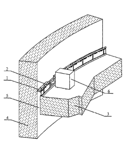
Fig. 1 represents a general view of the containment building separation system
at NPP in a
preferable embodiment which includes the following components: air-inflated
shutters 1 installed on a
support structure elements which are attached to the floor slab 3; the
shutters are connected with a
manifold ring 2 connected to an air blower 6 installed on the floor slab 3 The
air-inflated shutters 1 are
filled with air and are designed to close the circular gap 5 between the floor
slab 3 and the containment
building wall 4.
Fig. 2 represents a preferable embodiment of an air-inflated shutter 1
installed on a support
structure element and connected to a manifold ring 2 by means of a pipe, the
shutter shown in the figure is
ON.
Fig. 3 represents a sectional view of the containment building separation
system during the
normal operational mode. The containment building separation system is
installed between the floor slab
3 and the containment building wall 4 inside the circular gap 5 and includes
the air-inflated shutters I
connected to the manifold ring 2, the circular gap 5 is fully closed with the
air-inflated shutter I.
Fig. 4 represents a sectional view of the containment building separation
system at the moment of
shock wave impact. The containment building separation system is installed
between the floor slab 3 and
the containment building wall 4 inside the circular gap 5 and includes the air-
inflated shutters I connected
to the manifold ring 2, the circular gap 5 is partially opened after the shock
wave impact resulted from the
pressure drop in the lower premises.
Date Recue/Date Received 2020-12-01
Fig. 5 represents a sectional view of the containment building separation
system after the air-
inflated shutter 1 is deflated. The containment building separation system is
installed between the floor
slab 3 and the containment building wall 4 inside the circular gap 5 and
includes the air-inflated shutters 1
connected to the manifold ring 2, the circular gap 1 is fully opened.
Embodiments
The preferable embodiment of the containment building separation system
consists of the
following components: a containment building separation package located in the
circular gap 5 between
the floor slab 3 which divides the containment building rooms one from
another, and the containment
building wall 4. The containment building separation package is represented
with air-inflated shutter 1
tightly adjoining each other, this arrangement makes it possible to have the
circular gap 5 fully closed
during normal operational mode. Air-inflated shutters 1 are installed on a
support structure which is
attached to the floor slab 3 dividing the containment building rooms from each
other. Wherein air-inflated
shutters 1 by means of pipes are connected to the manifold ring 2 through
which the air is supplied to the
shutters from the air supply unit. The air supply unit, in the preferable
embodiment, is represented with 2
blower fans 6, one of them supplies the air to the manifold ring 2, and the
other one is redundant. Wherein
both of the blower fans are equipped with return valves to prevent the air
backflow through the redundant
blower fan. The containment building separation system includes also a control
module not shown in the
figure, connected to the pressure transmitters not shown in the figure, which
are located in various zones
of the containment building.
In one of the embodiments it is possible to connect the manifold ring 3 to the
ventilation system
of NPP containment building, instead of using an independent blower fan 6
Date Recue/Date Received 2020-12-01
-
CA 03028931 2018-12-20
NPP containment building separation system in the preferable
embodiment functions as following: In normal operational mode one of the
blower fans 6 injects pressure into the manifold ring 2 via a return valve.
The
air-inflated shutters 1 are, therefore, filled with air and fully close the
circular
gap 5 between the floor slab 3 and the containment building wall 4, as shown
in
Figure 3. Thus, the upper room of the containment building is fully isolated
from the lower one, where the radioactive background is higher, and NPP
personnel can attend this upper room for servicing the machines and plants
inside this room. According to the calculations, to ensure reliable insulation
between the upper room and the lower room it is enough to have the circular
gap
5 95% closed, in this case the forced-flow exhaust ventilation system will
generate the pressure drop between the room which will be sufficient to
prevent
upstream airflows from the lower room to the upper room. A system control
module monitors the indications of the pressure transmitters inside the
containment. In case one of the blower fans 6 fails, the control module
activates
the second blower fan 6 to have the circular gap 5 fully closed, this will
allow
the NPP personnel to carry out instant field repair of the collapsed blower
fan 6
without being exposed to any radioactive hazard.
If a severe accident occurs, for example, a breakage of a pressurized water
supply pipeline located in the lower section of the containment took place,
this
damaged pipe caused a high pressure zone of steam and gas mixture to appear,
the mixture includes hydrogen among other gases, this high pressure zone
generates a shock wave which rushes through the air-inflated shutters I at one
of
the circular gap 5 segments, as shown in Figure 4. This became possible
because
the air-inflated shutters I are made of fabric, and, therefore, they are
flexible and
vulnerable to shock wave impact. The shock wave impact is distributed within
both of the containment zones, and the pressure onto the containment building
walls 4 is reduced. The pressure transmitters indicate sharp pressure rise
which
is registered by the control module. The control module deactivates both of
the
CA 03028931 2018-12-20
blower fans 6. In practice when the pressure inside the containment rises
above
0.129 MPa so called setpoint pressure' all electric systems are deactivated,
which means that blower fans 6 are switched off as well. When NPP ventilation
system is used for supplying air to the containment building separation
system,
it is also deactivated following the above the pressure rise. As a result all
air-
inflated shutters 1 along the whole perimeter of the containment get deflated
and
return to a vertical position, as shown in Figure 5, so the circular gap 5
becomes
fully open. In the preferable embodiment the air-inflated shutters 1 are made
of
fabric to ensure instant deflation through the pores of the fabric when No.
air is
supplied from the blower fans 6. This ensures uniform distribution of hydrogen
concentration and pressure of steam and gas mixture throughout the whole
containment to protect the walls 4 of the containment and keep them free of
damage. Besides that, the water which was sprayed by sprinkler systems located
under the dome of the containment flows through the open circular gap 5
directly into the catch pits tanks of the containment.
After a severe accident has been localized and the consequences were
eliminated, it is possible to instantly close the circular gap 5 by activating
the
blower fans 6. This will provide for the insulation of the manned upper room
of
NPP containment from the source of radioactive emissions, and due to this
insulation it will be possible to arrange the process of NPP recovery to
restore
normal operational mode as soon as possible.
In one of the embodiments it was offered to add to the manifold ring a
pipe for uninterrupted discharge of air into the containment airspace. In this
case
the pressure produced by the operating blower fan 6 will be sufficient to keep
the shutters inflated, after the blower fans get OFF as a result of any severe
accident, the shutters will be deflated and the air will be discharged through
this
pipe. Using the pipe for continuous air discharge is not a pre-requisite for
implementation of this invention, but it makes the process of air discharge
from
the shutters 1 faster, and therefore, opening of the circular gap 5 also
becomes
11
.5 YY, y .44/ Yi===
CA 03028931 2018-12-20
faster. Another embodiment offers to use the air discharge pipe activated with
a
command from the control module following the pressure drop or if the pressure
inside the containment reaches the setpoint value.
Using blower fans or air blowers 6 for supplying air to the containment
building separation system is a recommended choice as compared with using the
plant ventilation system, as they make a containment building separation
system
independent of the ambient conditions inside the containment.
In the preferable embodiment the containment building separation system
contains vertical service tunnels located between some of the air-inflated
shutters.
It is also acceptable to use metal shutters instead of air-inflated fabric
shutters 1, however, this embodiment has some disadvantages. In particular,
metal shutters are quite heavy, so to have them capable to let the shock wave
impact through, a complicated mechanism is required, which includes special
louvers, and this complicated design will influence the reliability of the
shutters.
It is assumed that the service life of air-inflated shutters 1 made of fabric
is longer than the NPP service life, the design of air-inflated shutters 1
makes it
possible to replace the shutters very quickly. A factory-made design includes
an
air-inflated shutter 1 made of fabric and attached to the support structure
used
for installation of the whole system onto the support base, the shutter is
fixed to
the support structure with two pins.
Industrial applicability
NPP containment building separation system provides for the enhanced
safety level both in normal operational mode, and during severe accidents, and
is
applicable for any type of containments.
12