Note: Descriptions are shown in the official language in which they were submitted.
Background of the Invention
The present invention relates to a novel reinforcement
member for flexible drive belts and, more particularly, to a
novel reinforcement member and method of manufacturing timing
belts. The present application is related to the subject matter
of U.S. Patent No. 4,681,5~8, filed in the name of the present
inventor and assigned to the assignee of the present invention.
Timing belts are flexible drive belts, similar to
pulley-type belts, which have teeth on one or more sides of the
belt which permits the belt to perform much as gears perform in
transmitting precise precision motion. Timing belts, also known
as synchronous belts, generally do not transmit the amount of
power that a gear will transmit, but offer light weight and
alignment flexibility with the advantage of non-slip precision
motion transmission. In such precision motion transmission, the
motion is transmitted by the pulley teeth meshing with the belt
teeth and during the meshing operation of the engagement and
dlsengagement of the teeth, relative movements take place between
the pulley teeth and the belt teeth. Accordingly, several prior
art structures and compositions have been suggested for
manufacturing belt structures which provide a high degree of
flexibility while maintaining the necessary wear and life
characteristics of the belt.
Belts for transmitting motion have been known for many
years, as evidenced by U.S. patents 1,928,869, 1,611,829,
3,464,875 and 4,266,937 which describe processes in which the
cogs or teeth are preformed in some manner and placed about a
drum and then the remaining portion of the belt components or
belt sleeve is wrapped around the teeth to form the completed
uncured belt sleeve. More recently U.S. patent 4,487,814
describes a belt construction and the method and manufacture of
the same.
Conventional timing belt constructions for industrial
use, which include V-belts and drive belts constructions, are
~enerally comprised of a polymeric matrix material,
3~i~
--2--
such as, rubber or polyurethane, and the like, reinforced
with a higher strength material, primarily glass, fabric
or an arumid, and ~ith an even higher Young's modulus
filament, primarily metal, so as to resist stretching and
malntain precise belt-tooth spacing under operating load
conditions. Moreover, such timing belts, containing glass
or fabric reinforcements, generally do not possess
sufficient Young's modulus coefficients to withstand
stretching or elongation of the belt during operating
loads. Thus, the preferred reinforcement is generally
a metal, such as steel.
~ lthough, timing belts comprised of rubber reinforced
with metal filaments, such as stee] cables and the like
have been suggested, such belt structures present problems
relating to corrosion of the metal within the belt,
slipping and fatigue of the metal during operating load,
adhesion problems with respect to the metal to the rubber
reinforced belt construction and the difficulty of
producing a belt construction possessi~g the necessary
flexibility and stretch required in order to effectively
utilize steel as a reinforcing member of the belt. The
flexibility of the belt is necessary to prevent, during
the operating load conditions of the belt motion
transmitted from the pulley teeth meshing with the belt
teeth, the engagement and disengagement of the pulley teeth
and the belt teeth with respect to each other, which action
results in substantial teeth wear in that portion of the
belt construction.
Importantly, also, and perhaps the most important
difficultly associated with the use of steel as the
reinforcement tensile member within a belt construction,
relates to the difficulties associated with the use of
steel in the method of manufacturing for timing belts.
In general, timing or drive belts are manufactured by
applying an inner rubber reinforced layer from a continuous
sheet around a mandre] drum havin~ an outer surface
longitudinally grooved, which arooves provide the internal
teeth molded structure in the timing belt construction.
3~
Thus, initially, a continuous layer of uncured rubber
reinforced material is positioned and layed around the
mandrel to form a tubular sleeve of material.
Conventionally, a reinforcement cord or filament is then
wrapped about the inner reinforced sheet of rubber
continuously across down the length of the tubular sleeve.
Next, an outer rubber protective layer is stitched and
wrapped about the reinforcement cord or filament wrap and
the resultant uncured long layered tube of rubber
reinforced material is placed in a curing apparatus to
cure the composite structure. Thereafter, c~tting knives
are positioned adjacent the sleeve to cut predetermined
widths of the timing belts off of the formed and cured
composite sleeve to produce the dimensioned timing belt,
as desired. ~owever, during the cuttina operation of the
layered and cured sleeve, the reinforcement material is
cut and exposed at the sides of the cut belt. Such exposed
steel ends behave poorly in use and cause difficulty during
the cutting operations. Moreover, such structures permit
corrosion and the tendency of the steel fila~ent cord to
move out of the side of the belt, to catch moving parts
of the mechanical device. Such difficulties result in
a timing belt construction which is unsatisfactory and
a timing belt that possesses a short operating lifetime.
It follows that great manufacturing difficulties are
introduced to overcome the above described deficiencies
of having the reinforcement material emerge from the belt
assembly sidewalls.
The above-described drawbacks and shortcomings of
the prior art belt constructions and the conventional
method of manufacturing timing belts and other types of
V-belts or drive belts, and the secondary difficulties
associated with the manufacture of such belt structures
will be hereinafter described with reference to FIGS. 1-7.
As shown in FIG. 1, a cylindrical metal mold or
mandrel 18 having longitudinally extending grooves 18a
or teeth 19 on the outer surface thereof is provided as
the former for the belt construction. In FIG. 2, a strip
o~
of uncured polymeric matrix material 20 is positioned about
the outer surface of the metal mandrel 18 to provide the
gear tooth engaging wear surface 14 portion of the prior
art belt construction or assembly 30. The strip of
polymeric matrix material 20 may be wrapped several times
around the mandrel 18 to provide a wear and friction
surface Dortion of a belt assembly and is comprised of
a reinforcing fiber material 22 disposed substantially
uniformly throughout the polymeric matrix material 20 to
provide the gear-tooth wear surface portion 14 of the belt
assembly 30. During manufacture, the application of the
strip of polymeric matrix material 20 is sufficient to
provide the desired buildup and thickness of the gear-tooth
wear surface portion of the prior art belt assembly 30.
As shown in FIG. 3, the next step in the process for
manufacturing a cog or tooth-type belt construction or
assembly 30 is the positioning of the reinforcing cord
or filament 24 about the strip of polymeric matrix material
20. Generally, as described in U.S. patent 3,188,254,
the reinforcing cord 24 is spirally spun around the
periphery of the strip of polymeric matrix material 20
and applied under high tension. The reinforcing cord 24
may be of such material such as nylon, rayon, polyester,
glass fibers or steel and the application of the cord about
the mandrel assists the polymeric matrix material 20 in
flowing into the grooves 18a between the longitudinal teeth
19 of the mandrel 18.
After the reinforcing cord or filament 24 has been
wound about the mandrel 1~, as shown in FIG. 4, an
additional sheet or cover layer 22 of a plastomeric or
rubber material, of a type known to those skilled in the
art, is positioned around the wound reinforcing cord and
matrix material and stitched thereon to complete the raw
uncured tubular sleeve of belting material. Thereafter,
tubular sleeve and mandrel assemhly is positioned in a
conventional steam vulcanizing process, which is well known
in the art, to complete the vulcanizing process of the
belt assembly. During curing or vulcanization, there is
aclditional flow of rubber or elastomeric material
throughout the composite structure to provide a cured
integral belt sleeve, the composite 2S shown in
cross-section in FIG. 5. Thereafter, as shown in FIG. 6,
the cured belt sleeve on the mandrel is removed from the
curing mold and cut by knives 26 into individual belt
constructions or assemblies 30, as shown in FIG. 7 and
disclosed in U.S. Patent ~,487,814. As shown in FIGS. 3
and 7, because the reinforcing cord or filament 2~ is
spirally wound about the mandrel, when the individual belts
are cut from the cured sleeve, the cutting operation
necessarily provides a plurality of areas on the cut side
of the belt assembly 30 where the steel reinforcing cord
or filament 24 is exposed along the side and at the ends,
as shown by 28 in FIG. 7. These exposed ends permit
corrosion within the belt assembly, which reduces operating
lifetimes of the belt assembly 30, and permit the steel
filament or other reinforcing cord to move out of the side
of the belt to catch on the mechanical devices driving
the drive belt.
Summary of the Invention
One object of the present invention is to provide
a novel reinforced belt assembly or construction which
is cut from a cured belt sleeve wherein the reinforcing
cord or filament material is positioned and sealed within
the body of the belt construction.
A further object of the present invention is to
provide a reinforcing cord or filament material comprised
of a reinforcing member associated with a carrier member,
with the carrier member being continuous in length in the
form of a ribbon, tape or extrudate ancl wherein the
reinforcing member possesses a Young's modulus greater
than the material comprising the extrudate or tape and
wherein the extrudate, tape or ribbon holds in a regulated
array the reinforcing member within or on the carrier
member. Such a reinforcement material permits discrete
winding thereof upon a mandrel to provide a structure which
permits the subsequent cutting of belt assemblies wherein
t3 ~;; L~
the reinforcing cord or member is positioned and sealed
within the body of the belt construction.
Still another ob~ect of the present invention is to
provide a novel method of manufacturing belt assemblies
5 or constructions.
A further object of the present invention is to
provide a laminated reinforcing material comprised of sheet
or ribbon oE a carrier member having foil strips of a
reinforcing memb r mounted thereon, possessing a Young's
modulus greater than the carrier sheet, and which provides
a laminated reinforcing m~terial which may be
circumferentially wound about a mandrel to permit
subsequent cutting of belt assemblies wherein the
reinforcing member is positioned and sealed within the
body of the belt construction.
A further object of the present invention is
to provide a novel reinforcing cord or filament material
containing a reinforcing member maintained in a regulated
array by an elastomeric or polymeric carrier member, which
carrier member is compatible upon curing with the rubber
or polymeric material composition which comprises the
reinforced belt construction.
srief Description of the Drawings
FIG. l is a perspective view illustrating of the
cylindrical metal mandrel utilized in manufacturing
reinforced belt assemblies or constructions;
FIG. 2 is a perspective view illustrating the
application of a polymetric matrix material to the metal
mandrel in accordance with the prior art;
3n FIG. 3 is a perspective view illustrating the winding
of a reinforcing cord or filament around the mandrel during
a step in the manufacture of a reinforced belt assembly
in accordance with the prior art;
FIG. 4 is a perspective view illustrating the securing
of an outer rubber layer material to the wrapped belt
assembly shown in FIG. 3;
FIG. 5 is a cross-sectional view taken along lines
5-5 of FIG. 4;
:.-.. : .
.
FIC-. 6 i.s a fraamentary isometric view illustr~ting
the cutting of the belt sleeve after curing to produce
an endless reinforced belt construction in accordance with
the prior art;
FIG. 7 is a fragmentary isometric view with parts
in cross section illustrating a typical belt construction
in accordance with the prior art;
FIG. 8 is a fragmentary isometric view with part in
cross section of one embodiment of a reinforcina cord or
filament material in tape form illustrating a reinforcing
member embedded within an extruded carrier member or body
in accordance with the present invention;
FIG. 9 is a fragmentary perspective view illustrating
the circumferentially positioning of the reinforcing cord
or filament material about the mandrel during a step in
the manufacture of a reinforced belt assembly in accordance
with the present invention;
FIG. 9A is a cross-sectional view taken along lines
9A-9~. of FIG. 9;
FIG. 10 is a fragmentary isometric view with part
in cross section illustrating a reinforced belt
construction or assembly in accordance with the present
nvent lon;
FIG. 11 is a fragmentary i.sometric view of a further
embodiment of the reinforcing cord or filament material
comprising a reinforcing cable element held in a regulated
array on an elas~omeric or polymeric carrier sheet member
or tape in accordance with the present invention;
FIG. 12 is a fragmentary isometric view of a further
embodiment of a reinforcing cord or filament material
comprising strips of a re.inforcing member deposited in
a regulated array on a carrier sheet member in accordance
with the present invention;
FIG. 13 is a cross-sectional view taken along lines
13-13 of FIG. 14; and
FIG. 14 is a perspective view illustrating the
depositing of the embodiment of the reinforcing member
of FIG. 12 one upon the other to provide a laminated
. ~ .
. . .
reinforcing material in accordance with the present
invention.
Detailed Description
Referring now to the drawings of FI~. 8~ wherein
like numerals have been used throughout the several views
to designate the same or similar parts, in FIG. 8 there
is shown a reinforcing cord or filament material or portion
24 which is in the form of a continuous length of tape
or ribbon. The reinforcing cord or filament material 24
is comprised of a plurality of reinforcing members or means
12 embeddea within an extruded carrier mem~er or body 16
in a regulated array. The carrier member or body 16 may
be in the form of a tape or ribbon which is utilized in
the present lnvention hy circumferentially winding the
reinforcing cord or filament material 24 about the applied
strip of polymeric matrix material 20, which is first
applied during the manufacturing of the reinforced belt
assembly or construction 10.
The continuous length of reinforcing material 24 is
circumferentially wrapped about the strip of polymeric
material 20, that has been positioned on the outer surface
of the mandrel 18, as shown in FIGS. 3 and 9. The
resultant configuration of the wound reinforcing material
24 is schematically depicted and shown in cross section
in FIG. 9A. As depicted in FIG. 9A, the reinforcing cord
or filament material 24 is circumferentially wrapped around
the mandrel 18 ~not shown) having the strip of polvmeric
matrix material 2~ positioned thereon. The reinforcing
cord or filament material 2~ is circumferentially wrapped
in an overlapping relationship to provide at least more
than one convolution of the reinforcing cord or filarnent
material 2~ around the mandrel and strip material 20 to
provide the novel reinforced belt construction in
accordance with the present invention. As schematically
shown in FIG. 9A, the reinforcing cord or filament material
is wrapped twice about the mandrel 18. ~hus, it is
preferred that more than one convolution of the reinforcing
filament material is desired to reduce frettinq and to
3~
increase flexibility of the cured reinforced belt assembly
or construction 10.
As sho-n in FIG. 9A, the dotted lines 31 represent
the area between the positioning of the ribbon of
reinforcing cord or filament material 24 about the mandrel
and represent the cutting lines or area engaged by knives
25 which cut the cured belt sleeve to provide the
reinforced belt assembly or construction 10 in accordance
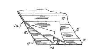
with the present invention. Additionally, as shown in
1~ FIG. 10, the side walls lOA and lOB of -the completed and
cut belt assembly or construction 10 do not have any
reinforcing member 12 extending outwardly therethrough
and the novel reinforced belt assembly or construction
10 in accordance with the present invention provides a
sealed and uniformly reinforced belt construction. Also,
as schematically shown in FIG. 10, the reinforced belt
assembly 10 includes a reinforcing cord or filament
material 24 having 5 reinforcing cable members 12 embedded
within the extruded carrier body 16 wound twice upon
itself. The reinforcing members 12 may be brass coated
steel cord having a plurality of filaments stranded into
a cable r as is well known in the cable stranding art.
The extruded carrier body 16 may be comprised of a rubber
based material which will substantially cure and fuse with
the remainin~ body portion of the belt assembly during
curing or vulcanization of the belt assembly sleeve.
E70wever, for polyurethane belt assemblies, the extruded
carrier body 16 may be comprised of polyurethane or a like
material which is compatible with the matrix or body
component of the belt assembly.
FIG. 11 illustrates a further embodiment of the
present invention wherein the reinforcing cord or filament
material 24 include a reinforcinq member or portion 12
deposited on and held in a fixed array upon a carrier sheet
or member 16. The reinforcing member 12 may be comprised
of a wire, strand, braid, or ~oven tape deposited in a
regulated and continuous array on the carrier sheet 16
and is held in fixed array thereon by an adhesive or other
--10--
sealing means. As previously set forth with respect to
the embodiment shown in FIGS. 8-10, the novel reinforcing
cord or filament material 24 is circumferentially wound
around the mandrel 18, having the polymeric matrix material
20 deposited on the outer surface of the mandrel,
preferably, more than one convolution, to build up the
desired reinforcing cord or filament material within the
body of the reinforced belt construction. Again, the
carrier sheet 1~ may be comprised of a rubber based
composition or other polymeric matrix material, such as
polyurethane. It being sufficient that the carrier sheet
or tape member 16 possesses the property and function of
being compatible with the composition of the cured
reinforced belt construction to provide a unitary
reinforced belt assembly 10.
FIGS. 12-14 illustrate a Eurther embodiment of
the present invention wherein the reinforcing cord or
filament material 24 includes thin foils or strips of-steel
12 deposited in a regulated and fixed array onto a thin
carrier member or sheet 16. The carrier member or sheet
16 may be comprised of any polymeric matrix material such
as rubber, polyurethane or other plastic and be in the
form of a tape or ribbon. The deposited thin steel foil
strips are, preferably, spring steel of approximately
25 1/1,000 of an inch thick which are held in fixed array
on the carrier sheet 16. The reinforcing cord or filament
material 24 is circumferentially wrapped about mandrel
18, as previously set forth, to provide a laminated type
reinforcing material, as shown in cross-section in FIG. 13,
contains at least 5 wraps of the thin foil reinforcement
material 24. The overlapping wraps of the reinforcing
filament material 24 align the thin foil strips of steel
one on top of the other and permit the buildup or
lamination of the reinforcing material 24 within the
reinforced belt construction to provide a laminated
reinforced belt construction, which is heretofore been
unattainable in the art. For example, thin foil strios
of spring steel l~l,OOOth of an inch in thickness, when
deposited on a plastic carrier sheet and wrapped 10 times
around the mandrel, produces a reinforcing cord or filament
material 24 having a thickness of approximately 10/l,OOOth
of an inch in thickness, a structure which possesses
5 superior flexibility and resistance to fretting than a
reinforcing cable member having a dimension of 10/l,OOOth
of an inch in thickness. Such a laminated reinforced cord
or filament material 24, when aligned and positioned about
the mandrel, permits cutting between the wound laminated
reinforced material on the reinforced belt sleeve to
provide a reinforced belt assembly or construction 10
having the laminated reinforcing material 24 embedded
completely within the cut side walls of the belt assembly,
a result that has heretofore been unattainable in the art.
It is within the scope of the present invention
that the reinforcing material 24 stock, which is in a tape
or ribbon form, may be comprised of a width greater than
the width of a reinforcement array necessary for a single
belt assembly which stock may be circumferentially wound
onto the mandrel 18 during the manufacturing of the
reinforced belt assembly 10.
A further embodiment of the present invention
includes a strip of reinforcing materia] 24 for use in
reinforced belt constructions or assemblies 10 which
includes a substantially flat braid of metal filaments.
The braid of metal filaments may include a carrier member
12, therein and extending the length thereof, comprised
of non-metallic material, such as, polymeric filaments,
glass filaments, natural filaments or mixtures thereof.
The striP of reinforcing material is circumferentially
wound around the mandrel 18, having the polymeric matrix
material 20 deposited thereon, under tension for more than
one convolution to build up the desired laminated
reinforcing material 24 within the body of the belt
construction, as has been set forth above, to provide the
belt assembly 10.
Additionally, another embodiment of the present
invention includes a strip of reinforcing material 24 for
use in reinforced belt constructions or assemblies 10 which
includes a woven tape of metal filaments, meta~ cable or
metal braid. The woven tape of metal filaments may include
a carrier member 12, therein and extending the length
thereof, comprised of non-~etallic material, such as,
polymeric filaments, glass filaments, natural filaments
or mixtures thereof. The woven strip of reinforcing
material is circumferentially wound around the mandrel
18, having the polymeric matrix material 20 deposited
thereon, under tension for more than one convolution to
build up the desired laminated reinforcing material 24
within the body of the belt construction, as has been set
forth above, to provide the belt assembly 10.
~ hat has been described is a novel reinforced
belt assembly or construction containing a laminated
reinforcing material therein and a novel method of
manufacture of such reinforced belt assemblies which
provides for reduced fretting, increased belt flexibility
and the elimination of exposed reinforce~ent ends cut
sidewalls of the belt assembly.