Note: Descriptions are shown in the official language in which they were submitted.
METHOD AND APPARATUS FOR THAWING OF ORE OR CONCENTRATE
CONTAINED IN A RAILROAD CAR
This invention relates to thawing of ore or
concentrate which freezes in railroad cars during
transportation in cold weather.
Transportation of wet ore or concentrate in
railroad cars in cold weather results in freezing of the
water in the ore or concentrate and this ice must be
meltsd before unloading of the railroad cars. Thawing of
ore or concentrate is normally done by entering the cars
into so called thaw sheds which are large enough to
accommodate a number of cars and heating up the cars using
steam heaters or direct-fired hot-air heaters. This
operation is expensive because a lot of energy is-lost in
heating the shed and the cars.
It is therefore the object of the present
invention to provide a new method of thawing ore or
concentrate wherein the heating energy is applied directly
to the ore or concentrate in the cars instead o~ being
applied to the aars to heat up the material inside the
cars.
The method in accordance with the present
invention comprises tha steps of inserting current
conducting electrodes in the ore or concentrate in the
railroad car, and applying a voltage source to the
electrodes to cause a current of sufficient value to flow
through the electrodes to produce heat and melt the ice
around the electrodes.
The temperature o~ the ore around the electrodes
.~
f~
-2-
or the amount of current flowing khrough the electrodes is
preferably monitorad to limit the ~low of current through
each electrode so as to prevent boiling of the melted ice
around the electrodes.
The system for carrying out the method in
accordance with the present invention comprises means for
inserting current conducting electrodes through the ore or
concentrate in the railroad car, and means for connecting
a voltage source to such electrodes for flowing an
electric current of sufficient amplitude through the
electrodes to produce heat and melt the ice around the
electrod~s.
The voltage sourcP preferably comprises a three-
phase transformer with a star connected secondary winding
so as to allow connection of the neutral common point of
the secondary winding of the transformer to the car
structure.
Thermocouple~ may be inserted into the ore or into
a hollow electrode to monitor temperature o~ the ore
around the electrodes. Similarly, current transformers may
be connected to tha electrodes to monitor the current flow
into the electrodes. The output of the thermocouples and
o~ the current transformers may be used to control the
f~ow of current through the electrodes to prevent boiling
of the melted ice around the electrodes.
~ datalogger may be provided to register
temperature, current and voltage data. This data may also
be stored into a microprocessor for analysis or treatment.
~;2~
-3-
The invention w~ll now be dlsalosed, by way o~
example, with reference to the accompanying drawings in
which:
Fiyure 1 i]lustrates a schematic diagram o~ a
system which may be used ~or thawing of ore or concentrate;
Figures 2 a and b illustrate location of the
electrodes, current trans~ormers and thermocouples in a
railroad car;
Figures 3 and 4 illustrate the variation o~
current in selected eleotrodes versus time; and
Figure 5 illustrates the variation of temperature
and the energy consumed in a typical electrode versus
time.
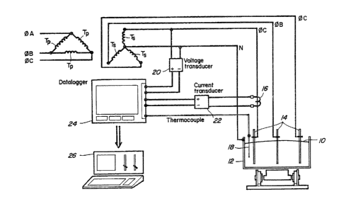
Referring to Figure 1, there is shown a schematic
diagram o~ a system which could ba used ~or thawing ore or
concentrate lo contained in a railraod car 12. A~ shown in
Figures 2a and 2b, three rows of electrodes 14 are driven
into the ore up to a few inches,from tha bottom o~ the
car. The electrodes are connected to the secondary
2Q windings Ts of one or several three-phase trans~ormers
depending on the electrical load and their connection is
evenly distributed ~o as to balance the load hetween the
phases ~A, ~B and ~C. The secondary windings Ts of the
transformers are preferably skar connected so as to permit
connection o~ the neutral N to the car structure.
Current transformers 16 may be pro~ided for
monitoring the current flowing through selected
electrodes. Thermocouples 18 are also inserted at
d ~
selected locations into the ore to monitor the temperature
of the ore at such location. The voltage and current
parameters are detected by transducers 20 and 22,
respectively, and fed to a datalogger 24. The thermo-
couples are also connected to the datalogger in order toregister all the data at various time intervals during
thawing. A microprocessor 26 may also be provided for
registering all data on magnetic discs for analyses or
treatment.
Prior to making full thawing tests, a few
preliminary tests were done to determine where the heat
was generated during thawing. The concentrate tested
contained 12.7% of water, 24.9% Cu, 0.12%Pb, 0.7% Zn, 0.1
oæ. per ton Au and 2.35 oz. per ton Ag. It has been found
that the main heat source is due to the contact resistance
between the electrodes and the ore which surrounds the
electrodes. This resistance varies between a fraction of
an ohm to a few ohms from one electrode to the other
because the ore is not uniformly distributed th~oughout
the car and thus the ore contact area with each eleatrode
is not the same.
It has been found that the ore itself is a good
conductor and that very little heat was generated by the
flow o~ current through the ore. It was also found that
the contact resistance between the car and the ore was
also low. Furthermore, the heat generated by suoh contact
resistance is dissipated on a large su~ace area which
tends to minimize its e~ect.
1~;2~
--5~
The results of a ~ull scale test on thawing of a
concentrate o~ the above composition contained in a
railroad car are illustrated in the following Tables
wherein Table 1 gives the temperature measured by thermo-
couples located at selected locations TJl-TJ16 as
indicated in Figure 2b of the drawings at various time
intervals, and Table II gives the currents I measured in
phases ~A and 0C and I4-I9 measured in selected
electrodes as also indicated in Figure 2b. The voltage
applied, power dissipated, and electrical energy consumed
as the test proceeded are also illustrated in Table II.
~62~jt~
--6--
TAB L~ I
~o
- U O O O ~ ~ ttl Ul ~O O `O O O ~ I~ ~ O ~ CO N 0. _ O M N O O N 1 `O ~t O -- `:t O O t~ N ~ N 1~ ~ Il~
t- _ _ _ N ~ `O 0~ X o o O o o o o o N o N 8 ~g Z~ ` CO ~ ~ Ul N 0~ O ~ N O 0~ _
m N N 1`- `O ~t _ M 00 0 `O O `O ~ ~ 0 ~ 1~ 1'7 N _ _ O . O O N O N _ N _ t l _ ~ N r ~
U ~0 '.0 1~ lil 11~ 11'1 ~ ~ '1 ~ 7 N N ~ -- i O O O O O O O _ N ~ `O ~ 0~ 0~ O O O
o 0 0~ N ~O _ ~ _ _ ~ 11'~ ~O `O CO O _ _ ~ O~ O O --~ ~ N O~ I~') O U~ `O O ~ CO 1`. 00 N ~ O
U `O U~ t ~ N _ ,0 0 0 0 0 0 N M N ~ ; 1~ N N
M _ _ 1~. Ul ~r o N `O 0~ U~ O 1~ 111 1~ N N _ N . ~ N M O ~ O ~ O `O N Ul O 1~ 0~ IUl 00 CO U~ `O Ul ~0 N ~0 1~
~ ~ ~ ~ ~^ N ---- -- O O o o O O O O O M ~ `O ~ 0~ M ~ CO ON X ON~ M M M N N N ~I N--
N ~ 1/~ `.0 M _ In N i~ O o 1~ M N ~ N 1~ 0~ M ul O O` M M U~ N ~ ~ ~0 `O 00 O ~ ~ ~ t ~ N N M O`
0 `O ~ N O O O O O O O O O a~ ~ R N M M ~; M 5 ~ M ~ ~ ~N 0~
-- ~ It~ ttl -- N ~ O ~ CO O ~ M 0 ~r `O 0~ ~ O 1'~1 N ~ 0~ 1~ O O ~ 1~') ~ `O ~ 11~ O` ~ N O M 0~ Ul ~ _ ~0 `O
t- --_ _ _ _ _-- _--_ _ _ _ _ _ _ _ _ _ _ _ _ _ _ _ _ _ _ _ _ _ ~ _
O ~N~t_ O N _ N N0~NN _ OO ON _N N~ ~ 1~ O1~! O 0~ ~O N_ O~--N~0~ 00~
7 # `0 `O U~ U~ ~ ~ M N ~ O , o o o o O o o o o O o O O O U~ 0~ N ~ `0 ~ N N~ ~N ` ` 2; N N UN~ N N
O O N ~ ~ N O `O ~ ~ r_ ~ t'l a~ ~ ~ `O 0 ~ N ~ M O ~ `;1 `O CO N ~0 0 _ ~ ~t O N U~ ~ O 0~ N ~r
_ ~ ~ `t ~ o ~ U~ ~ ~ ~ `D ~ N ~ U~ ` N N N O æ ~ ~ O N N N N N O ~
____ ____________ ~____~--____
~ O ~ u'l 0~ N _ _ _ O _ O _ O _ --~ _ N _ ~ 1~ O 0~ N _ M ~ CO ~ O
7 # ~ 1~ ~ ~ ~ 111 U~ ~ M N --_ _ O O O O O O O O O O O O O O O O O O O ~ N ~ U~ `O t~ ~
_ _ _ .-- _
_ O M _ O O 00 ~a 00 N `O M 11 _ _ _ ~ `O ~ U~ M `O N r~ a~ N _ N 0~ `O Cll O `O U~
t- ~ ' ~ ~ . . ' ' ~ ' ' ' . . ' --N ~ ~ ~ `;t ~ ~ u~ ) M 11 1-~ N N N
~It~OCO~ NU~N1~N0~M1.'1NMU~O1~00~1'~O~--M1~000~00NN
7 ~ ~MMNN___OOOOOO_~_N~NO_N~ N_N~O~_~
t~ -....' -~ NM~$~MNNN_
O~MMN~O~-~_N ~M~N~M~
# ,OOOOOO~ooo~ o~ ~MO
~_O~ ~MO~MMN_NM_ONN~MMN~N~_~NO~
7 # ~M~MNNN____ooooOOOoOooooooooooooo_~oNNMMN
t- .~............. --.--.... - ______
~O~N~N_O~_~N~O~O~N_NO_NN~
M ~ MMM~M~MNNN______OOOOOOOOOOO_O.O_OoooOOOo__
t- .-.---......... ....-.... ... .
N ~ OO~N~M~O~M~N~NN~O_~_~N~O~
t~ ,joiooooooooooN~oo-NNMMNNN
, ~ O~N~-~O~M~N~_~N~_N~_o_o~N
~ ~O_OO___NN~_~MMNN~O
Ul OOOOO~OOOOOOOOOOOOOOOOOOOOOOOOOOOOOOOOOOOO
N~ N~ NM~-N~-x~-~-~o~o~o~o~o~o
NNNNNNNNNNNoooo----NNNN~
. .
T~B L;~ I I
-
O t~i N l_ ~ $ ~g o ~ ~ ~ o ~ ~ ~ r~ ~-- N U~ ~
O N ~ ~ 0 ~ ~ _ ~ N ~ co ~ ~ ~a $ æ 5 N ~ N ~ ~
C~
3 0 ~ N ~ ~ 3 æ ~ ~ ~ ~ ~ O O
al 3 0 ~O O~ ~ ~ O ;~ N o ~ Ul N N ` ~ tO N U O O O O O
O ~ ~ O N 0:~ ~3 M ~ ~ U~
~o e _ N N æ N N _ _ N N N N N N N N N M M M N r 1 ~ ~ R M M M M t
.s r l ~ ~ ~s u~ 11'1 ~ $ i~ ~ o~ o _ o N M ~ 111
~t 3 o` ~ R `o u~o o o o o o o o o o o O
~1
3 ~ g ~ ~ N $ ~ o 7 U~ ~;; M ~ o
0 ~N ~ ~ ~ N 0 N `O 0~ ~ 0 N O
OOOOQOOOOOOOOOOO~OOOOOOOOOOOQOOO o
N ~2 ~ ~ X N ~ 'i ~ N ~ ~ `D ~N 'j~ 1` UNl ~ U~ ~ Ul U~ ~ U~ _ Ul O U~ O
: N N N N N N N ~N _ N N N N 1~ 11 ~ ~ ~ ~ In ~ U~
'
--8-
As shown in Table II and illustrated in Figures 3
and 4, the current in the electrodes increases (2 to 3
times its initîal value) as the ore heats up around the
eleatrodes. This is due to an improved contact between the
s electrodes and the ore as thawing proceeds and also to the
improvement in the conductivity of the ore as a funckion of
increase in temperature. The electrodes which make better
contact right at the beginning o~ thawing have a tendency
to experience a faster current incrQase than the others.
Consequently, more heat is developed around these
eleatrodes which increasss their conductivity even more.
This may be observed by comparing currents I4 and I9 in
Figure 3 and currents I6 and I7 in Figure 4. If the above
process continues without control, there will be enough
heat developed around the electrodes having lower contact
resistance to cause the water around the electrodes to
boil. This phenomenon must be avo~ded because the energy
re~uired to vaporize water is useless. This is illustratad
in Figure 4 wherein the temperature at TJ5 exceeded 100C
shortly after 2~4 hours of operation. If boiling is
continued, it will dry the ore around the electrode and
this may eventually cause a short-circuit. Thus, it is
preferable to limit the current in the electrodes to
prevent ~oiling and allow a more uniform thawing of the
ore. This may be done by means of a thyristor located in
the ~eed of each electrode. The current through each
electrode may be controlled khrough a feedback circuit
connected to the ~iring gate of the thyristor and
lt;7
, .
responsive to a thermocouple measuring the temperature
of the ore around the electrode or to a current
transfomer measuring the aurrent flowing through the
electrode.
In the above test, the average temperature of the
ore was raised from -5C to +15C in about 7 hours. The
energy required was about 1.1 MWh to thaw about 80% of a
car containing 96 tons of ore. Based on theoretical
calculation, it was found that the efficiency of the test
was about 90%. This efflciency would have been increased
if boiling around the electrodes had been controlled.
Subse~uent tests have proven that it was possible
to insert electrodes in frozen ore by the combined action
of pressure and heat generated by the electrode~ To that
effect, a group of sixteen 3/4 in electrodes were
installed on a supporting structure which was held above
a car of frozen ore by chain blocks. The supporting
structure was loaded with about 7,000 pounds of cement
blocks making up a }oad of about 430 pounds per electrode.
A three phase voltage of 100 V was applied on the
eleckrodes upon contact with the ore. The temperature was
about -5~C at the surface of the ore, -3C inside the ore
and the ambient air temperature -7C. Thawing was very
rapid near the point of the electrodes thus facilitating
their insertion into the ore. After 35 minutes, ~he
electrodes were fully inserted into the ore.
Although the invention has been disclosed with
refere.nae to a preferred embodiment, it is to be
--10--
understood that it is not limited to such embodiment and
that other alte.rnatives are also envisaged within the
scope of the ~`ollowing claims.