Note: Descriptions are shown in the official language in which they were submitted.
~262~7~
23,754 - 1 - PATEN'r
MULTI-LEVEL FUSER ~,AMP
TECHNICA~ FIELD
The present invention relates in general to tubular
incandescent lamps, and pertains, more particularlyl to such
lamps as applied in heating or photoreproduction processes.
BACKGROUND
A photocopy machine typically employs two different types
of lamps, one being referred to as an exposure lamp and the
other as a fusing lamp. The exposure lamp is purely for light
emitting purposes during the exposure phase of operation~ The
fusing lamp on the other hand is primaxily for heating purposes
to "set" the toner employed in the photocopy machine. In
accordance with the present invention, the principles thereof
are applied primarily in connection with a fusing lamp, but may
also be applied to other general heating purposes.
~Z6~7C~
23,754 - 2 - PATENT
Fusing lamps are typically of single filament construction
and have a length corresponding to the ma~imum size (length) of
paper that is to be reproduced. One infrared lamp, in
particular, has utilized two filaments disposed and
electrically connected in parallel within a quartz envelope in
order to allow substantially higher operating wattages to be
achieved by simultaneously energizing both filaments (see U.S.
Pat. No. 3,443,144 to Robert Freeze). According to Freeze, the
use of parallel filaments provides higher heat density per unit
area of envelope wall. The lamp in Freeze, as described, does
not provide for selective activation of the filaments (i.e.,
dual level fusing), to adjust for different incremental wattage
output requirements. Finally, the Freeze lamp provides a
series of spacers disposed along the length of the filaments to
prevent them from sagging against the guartz envelope, but does
not isolate the filaments from each other to prevent shorting.
In some photocopier applications it would be desirable to
have different levels of energy available for fi~ing the toner
(i.e., fusing) onto the copy of the original document. A high
le~el of energy is desirable at the time of starting to make
the first copy, as at that point the fusinq system is cold.
Typically, some time is required to bring the fusing system up
to operating temperature and may limit the speed in which the
first copy is supplied, which is one measurement criteria used
in photocopying machine evaluation. In U.S. Pat. No 4,442,374
to Morris et al, a dual length filament incandescent lamp is
provided that allows for two different lengths of fusing
usually at a prescribed amount of energy per length in order to
set toner on short paper and long paper equally, i.e., energy
per square centimeter of paper would be the same for both short
and lons paper. This then will result in two levels of total
lamp energy, but one level of fusing energy per length of paper.
l;~f;2 1 70
2 3, 7 5 4 - 3 - PATENT
It is believed, therefore, t~at a tubular incandescent lamp
provid~ng ~ul~iple levels o~ ~nergy fo~ heati~g ap21ications
whlle pro~oting co~pactness and ~anu~actur~ng ea~e would
con6titute a 6ignifica~t adva~cement in the art.
DISCLOSU~E OF THE INVENTION
It is, therefore. a primary ob~ect of thiG inven~ion to
enhance t~e tubular incandescent lamp art and particularly t~at
art invo~ving lamps having more than o~e ~ilament.
It is another object of this invention to provide a~
improved incande~cent lamp wherein the lamp is readily adapted
for use in application~ requiring multiple levels of energy for
heati~g.
Still another object of the invention i6 So provide an
improved incandescent la~p.which is compact, ca~ be produced
~oth at a lower co~t and on a mass production basis.
Xn accordance with one aspect of thi~ invention, there is
provided a tungste~-~alogen incandescent la~p ,compri6ing a
tubular quart~ e~elope having fir~t and second press sealed
end portions, a pair of coiled tungsten ~ilaments extendi~g
longitudinally through the interior of the tubular envelope and
a fill gas mixture di~posed within the envelope. The la~p
further include~ fir~t contact mean~ as~ociated with the f irfit
pres~ ~eale~ end portion and electrically coupled to a ~ir~t
end o~ each of the filaments, second contact ~eans as60ciated
~ith ths second press sealed end portion and electrically
coupl~d to a second end of one of the filaments, the ~ilament
being energized upon application o~ a predetermined voltage
across the fir~t and ~econd contact mean~. and third contact
means associated with the ~econd pre~ sealed end portion and
~30 electrically coupled to an unattached second end of one of the
:~2~
23,754 - 4 - PAT~N~
filament~, t~e filament being ene~gi~ed upon ~ppllcation of
predeter~i~ed ~oltage across the ~irst and third cont~ct
~eans. Pinally. the lamp al60 includes means for electrically
isolati~g ~ach of ~he filament~, the electrically i~olating
~ean~ diEp~6ed within and extendin~ lo~gitudinally through the
interior of the envelope.
B~IEF DESCRIPTION OF ~HE D~A~INGS
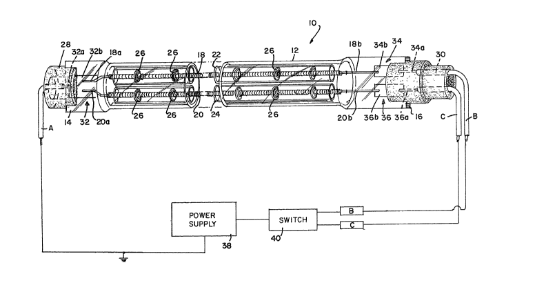
FIG. 1 is a 6ide view, partly in ~ection, illu6~ating one
embodiment of the in~tant invention and ~urthermore
illustrating the electrical ~witching control a~ociated with
t~e lamp; and
PIGS. 2A-~C illu~rate several view~ of another embodiment
of the instane inven~ion.
BEST ~ODE FOR CAR~YING OUT THE INVENTION
For a better under~tanding of the present invention,
together with other and further objects, advantage~ and
capabiliti~s thereof, reference i~ made to the following
disclosure a~d appended Claims in connection ~it~ t~e
above-de~crib~d drawing~.
~ith particular attention to ~IG. 1. a lamp 10 i~
illu~trated which comprises a tubular envelope 12 of vitreou6
material ~aving ~irst and second press-~ealed end portions 14
and 16. re~pectively. ~nds 14 and 16 are located at the
oppo6ed end~ of envelope 12 and are formed by utilizing
presfiing operations and apparatus known in ~he art. Envelope
12 should preferably be made of a material having a high
melt~ng point~ such as ~used ~ilica or quartz.
12~;2~7C)
23,754 - 5 - ~ATENT
La~p 10 i~ o~ the tung6ten-halogen var1ety~ there~ore it
ha~ a fill ga6 mixture containing an inert ga6 and a h~logen or
halide. In the pre6ent i~vention, t~e lamp~ are filled at
about o~e atmosphere Q~ argon (a~ the inert g~8 ) and ~ave about
200 miceogra~ of bromine (speci~ically methyl bromide). The
precedi~g ill constituen~s 6hould serve only to illustrate
wha~ the ~ompositio~al ma~e-up ~f a fill ga~ ture nor~ally
con6i6t6 of and not ~erve to limit the pLesent invention. Lamp
10 furt~er include6 a pair of tun~6ten filaments, 18 and 20,
which are dispo~ed wit~in envelope 12 and extend lo~gitudi~ally
through t~e interior of t~e envelope.
Previou~ lampsO especially the lamp in the Freeze patent
(U.S~ Pat. No. 3,443,144), have typically included ~eans ~or
6pacing or ~upporting the filament to prevent it ~rom touching
the envelope wall. The drawback~ to utilizing the ~pacer xeans
provided in Freeze involY~ the dif~iculty of inserti~g such a
6pacer within a ma~s produced lamp envelope and the
in6u~icie~cy of electrical i601ation between filament6 to
prevent po~6ible ~horting. Accordingly, the in~tant invention
uniquely provides mean~ for electri~ally i601ating the
filaments while promoting compactne~s a~d simplifying assembly
of the la~p.
In accorda~ce with the teachi~g~ of the present inv~n~ion,
filament~ 18 and 20, a~ illustrated in FIG. 1, are electrically
i~olated from one another by i801ating mean6. compri~ing tvo
tubes, 22 and 24. that are dispo~ed longitudinally within
envelope 12. Filament~ 18 and 20 extend longitudinally through
tubes 22 and 24, respectively. Tuba6 22 and 24 should be ~ade
o~ electrically infiulative material that is transparent and has
a high melting poin~, 6uch as quartz. Tu~es ~2 and 24 extend
the length of the interior of anvelope 12 to about 1 milli~eter
(mm) from pre6s sealed end portions 14 and 16. T~e filaments
- 6 -
could conceivably be sufficiently electrically isolated by
using one tube about one of the filaments. The filaments are
also hermetically sealed within end portions 14 and 16.
Supporting filaments 18 and 20 at preselected points (about
25.4 mm apart) along the length thereof are a plurality of
support members 26 (illustrated in FIG. 1), each comprising a
coil element having one end wound about (and thus secured to)
each of filaments 18 and 20 and the other end (of greater
diameter) positively engaging the interior wall of tubes 22 and
24, respectively. In the embodiment illustrated in FIG. 1,
filaments 18 and 20 possessed an overall length of about
350 mm. In addition, envelope 12 is T-5 quartz tube having
an outer diameter of about 15 mm with a thickness of about
1 mm. Tubes 22 and 24 are T-2 quartz tubes having outer
diameters of about 6 mm and thickness of about 1 mm.
To facilitate positioning of lamp 10 within the photocopier
designed for utilizing same, ceramic bases or end caps 28 and
30 are preferably used. Accordingly, it is only necessary in
the respective photocopier to provide some means for accepting
this component. Understandably, such a means can be of
relatively simple design. Ceramic bases 28 and 30 are also
preferably of substantially cylindrical configuration and
include a slot therein designed for having the flattened
press-sealed end portions, 14 and 16, inserted therein.
Filaments 18 and 20 are energized by means of applying a
predetermined voltage across contact means located within the
press sealed end portions of lamp 10. Specifically, first
contact means 32 is associated with end portion 14, while
second contact means 34 and third contact means 36 are
associated with end portion 16. First contact means 32 is
comprised of a first lead-in conductor 32a, which extends
externally from and internally within end portion 14, and a
1~;2~7~
23,754 - 7 - PATENT
foil portion 32b disposed within portion 14 and electrically
coupled to both conductor 32a and to a first end 18a and 20a of
filaments 18 and 20, respectivel~. Second contact means 3~ is
comprised of a second lead-in conductor 34a, which extends
externally from and internally within end portion 16, and a
foil portion 34b disposed within portion 16 and electrically
coupled to both conductor 34b and to a second end 18b of
filament 18. Finally, third contact means 36 is comprised of a
third lead-in conductor 36a, extending externally from and
internally within end portion 16, and a foil portion 36b
disposed within end portion 16 and electrically coupled to both
conductor 36a and to an unattached second end 20b of filament
20.
Lead-in conductor 32 is coupled to a lead wire A, which is
in turn coupled to the common terminal of a power source 38.
Lead-in conductors 34 and 36 are coupled to lead wires B and C,
respectively, while wires B and C are then coupled to a control
switch 40 that is coupled to power source 38. Leads A, B and C
are stranded 16 AWG (AWG - American Wire Gauge)
pol~tetrafluoroethylene insulated wire which is rated at 600V
and 200C. Lead wires B and C, through switch 40, are adapted
to apply a voltage across filaments 18 and 20, individually or
simultaneously. Filaments 18 and 20 may be of v~rying
wattages, but the total wattage output of filaments 18 and 20
together must be greater than either individually. In one
embodiment of the present invention, filament 18 is rated at
about 375 watts (120V) and filament 20 is rated at about 1250
watts (120V); the overall wattage output possible in lamp 10
would thus be about 1625 watts The overall length of lamp 10
is about 420 mm.
Referring now to FIGS. 2A-2C, a lamp 50 is illustrated
which is made in accordance with the teachings of the present
invention. The elements of lamp 50 that are common with those
.~a~.
,~, ,'~"
1'~62~70
23,754 - a - PAT~NT
of lamp 10 have been ~i~il~rly nu~bered and a d~tailed
description of these element~ i~ not believed necessary here
( ee FIG 2A). La~p 50 has an envelope 52 vhich contains
~erein i~olating means 54, ~hich isolates filament 18 fr
fila~ent 20. that extends lo~gitudinally ~herethrough.
i~olating ~ean6 54 co~prises an insulati~e divider which form6
at lea~t t~o chamber~ hin envelope 52 (~ee FI~. 2B). In
lamp 50, divider 54 i~ structu~ally a part oP envelope 52 and
extends to press sealed end por~ion~ 14 and 16 Sas partially
illu8trated in FXG. 2C). A8 illu8trated in FIGS. 2A and 2B,
divider 54 i~ 6ubstantially planar in configuration and forms
dual cham~ers within envelope 52 which are sealed a~ end
portion6 14 and 16.
In la~p 50, envelope 52 and divider 54 are formed fro~
quartz and may be formed in a single manufaceuring ~tep by
forming a quartz tube ~i~h dual bore~ or chamber~. A~ 6een in
FIGS. 2B and 2C, the quartz tube (or envelope 52~ ~ay ~ave an
elliptical shape with ~wo dome-~haped chambers wi~hin. In -
thi6 embodiment of lamp 50 (~ee FIG. 2B~, the tube has a
diameter "D" of about 15 ~m (millimeter6), ~ith an inner
diameter "d". of about 13 mm. Divider S4 has a length ~L~ of
abcu~. 11 ~m and the diameter of eac~ c~amber is about 6 mm.
Divider 54 of lamp 50 need not be a part of envelope 52, but
need simply be an insert that provide~ a 6i~ilar function as
de~cribed earli@r. Accordingly, the in~tant invention uniquely
provides ~eans for i~olating the filament~ while promoting
compactnes~ and ~i~plifying assembly of the lamp.
~ amp ~0 i~ similar to lamp 10 with re~pec~ to filament
lengths and wattages, fill ga~ mixture, overall lamp length,
lead wire cDnnections and lamp-circuit connection. Lamp~ 10
and 50 are lamps which provide infrared heating primarily for
photocopier machine application~ but are not li~ited to ~uch
23,754 - 9 - PATENT
application6. T~ese l~ps provide ~ultiple leYel6 o~ ~usi~g
energy per ~quare cQnt~e~ee of paper eegardlQs~ of the design
length, depending on the deman~s arising ~ro~ ehe particular
application, without unneces6arily co~plicat~ng the production
of such a la~p. Presently, the filament lengt~ may be designed
at a fixed length as needed for the particular application, but
~eans are provided for varying the amount of energy per ~quare
centimeter of paper by burning either filament separately or
~i~ultaneously to provide at least three level~ o~ fusing
. 10 energy total and per ~quare centimeter of paper.
Infrared lamp~ ~ade in accordance to the teachings o~ the
present invention ~ill ~igni~icantly improve a photocopy
machine fu~i~g ~ystem' 5 ~peed in achieving start-up
temperatures. For example, using the wattages already
descri~ed earlier for lamps 10 and 50, at start-up 1625 watts
of energy (both filament~ energized) is supplied to the fusing
system. Shortly thereafter (about 1 or 2 photocopies later)
the energy needed would 6hift to 1250 watts (one filament) and
then perhaps to 375 waets (alternate filament), 6till supplying
enouqh energy to fix t~e toner properly to ~he paper.
Depending on the fu~ing sy~tem, the higher ~attage filament may
be used ~or fusi~g and switching could be controlled by a
thermo~tat that could ~witch between filaments of differe~t
wattages as needed.
~hile t~ere have been shown and described what are at
present co~sidered the preferred embodiments of t~e inve~tion,
it will be obvious to those skilled in the art that various
chan~es and modifica~ions may be made ~herein ~i~hout departing
~rom the scope of ~he invention as defined by the appended
clai~