Note: Descriptions are shown in the official language in which they were submitted.
BREATH-SYNC~ONIZED CONCENTRATE~-OXYGEN SUPPLIER
This invention relates to a breath-synchronized
concentrated-oxygen supplier, and more particularly to
an apparatus which supplies oxygen-enriched gas to a
patient in synchronism with the inhalation phase of his
05 respiration.
With the recent progress in the medical art,
an increasing number of oxygen concentrators have been
used in inhalation therapy for patients suffering from
respiratory ailment or circulatory diseases. Particularly,
oxygen concentrators for home use have become remarkably
popular these days, because they are capable of concen-
trating the oxygen gas in air by the use of a household
electric power source through a simple operation, and
supplying such concentrated oxygen gas for medical use.
In the United States of America, a s~andard for the
home oxygen concentrator, namely American National
Standard Institute (ANSI) Z79. 13, 1981, has been
established under the guidance of Federal Food and Drug
Administration (FDA). Further, an international standard
for it, e.g., International Organization for Standardiza-
tion ISO 5059, is now ready to be published. In countries
where medical treatment at home.~revials, such oxygen
concentrators are used to eliminate the inconvenience
involved in the conventional oxygen distribution by use
.
-- 2 --
llV~
~ 3
of heavy pressure vesse]s such as gas cylinders.
In general, there are two kinds of rnethocls
for treating patients by inha`lation of oxygen gas or
the l-ike; ~amely, the so-called "closed circuit method"
05 and the so-called "open circuit method".
The closed circuit method uses a "facemask
apparatus" on ~he face or an endotracheal tube inserted
into the trachea of the patient and supplies the gas to
~he patient through a passage, which is airtightly
s~parated from the atmosphere and extends between the
breathing device, i.e.~ the respirator or the gas
supply system, and the patient's respiratory system.
This closed circuit method has an advantage in its high
inhaling efficiency, because the gas can be inhaled at
about the same concentration as that of the gas supplied
to the closed passage and the patient's breathing can
be assisted or adjusted by regulating the pressure of
the gas inside. However~ the closed circuit methocl has
a shortcoming in that it may cause irritation or
discomfort on the side of the patient becawse of the
covering of his mouth and nose and the direct insertion
of foreign swbstance in his trachea, Accordingly, the
closed circuit method has been used mainly for seriously
sick and unconscious patients or patients under anesthesia,
On the other hand, the open circuit method
uses a breathing passage which is open to the atmosphere,
In this method, the tip of the gas supplying tube is
inserted into the nostril or the mouth of the patient
~f~
SO clS to fee(l the gas Wi thout using any airtight connec~
tion between the apparatlls and the Eace or upper airway
of the patien~, and the irritation or discomfort on the
side o~ the patient are reduced and the patient is
05 allowed to speak, eat or drlnk during the inhalation
treatment by this method. Accordingly, this open
circl1it method is mainly used for mild cases in which
self-breathing is possible.
In the closed circuit type breathing apparatus,
oxygen or gas mixture for inhalation may be supplied in
response to the patient's spontaneous breathing by
detecting ~he gas pressure changes in the closed
respiratory circuit, because the latter can be used as
a triggering mechanism. ~lowever, in the conventional
open circuit type breathing apparatus, it is diEficult
to detect the ample pressure change enough to trigger
the gas supply in the open respiratory circuit, and in
most cases, the gas is supplied at a constant flow rate
regardless of the patient's breathing. Accorclingly,
the ~as is forced to the Ratient even during his exhala-
tion and cliscomfort has been caused to -the patient.
Besides, a large part of the constant]y fed gas is
wasted because the gas s-upplied during patient's exhala-
tion is discharged to the atmosphere without being used.
Besides, the open circuit type breathing
apparatus is suscep-tible to undue dilution of oxygen
concentration with air because it is open to the
atmosphere. To cope with such partial pressure reduction
,~.
''
,;'
,:
~ 3
of oxyg~n, it has b~erl prac~icecl to increas~ the 1.ow
rate of the const~nt.Ly fed gas. ~owever, the inventors
have ~ound that the transclltaneous tisswe parti.al
pressure oE o~ygen (tcPO~) :i.ncreases with the flow rate
onl.y up to 3 Q/min, and the oxygenation :in vivo hardly
Eurther increases even when the oxygen flow rate of
insuffl.ation exceecls ~he above value, as shown in
Table 1.
Table 1 TranscutanPous Tissu~ O~ygen Partial
Pres~ure for Di~ferent Constant Oxygen
Flow Rates through a Nas~l Cann~la
_ . _
Flo~ rate 0.5 1.0 2.0 3.0 4.0
_ ___ _ _ __
Oxygen partial
pressure 89.9~3.4 93.1+4.5 129.7+13.9 145.2+5.8 151.0~4.8
_ (~lg) , _ _ , __
,
Thus, when the oxygen flow rate is excessively high in
3wch an open c:ircuit type breathing apparatus, a l.arge
amount of the oxygen gas will be wastecl to the atmosphere
without being used by the livi-ng body. Furthe:rmore,
with a high f-low rate of oxygen, the stimulation to the
patient becomes too strong and patient's discomfort
increases. Accordingly, there is a limitation in the
constant flow rate oxygen ins-ufflation system in clinical
practice.
~ To overcome the shortcomings of the conventional
:'.
~.
, .
~ ~ ~q~ ~ ~ 3
open circu:i.t type breath-ing system, the .Japanese f)~tent
L~yi.ng-open Publ-icati.on No. 8,~72/8~ proposed a breath-
synchronized open circuit type breathing system.
In the breath-synchronized type~ oxygen gas ls supp'lied
'. 05 only during inhalations of the patient~ so that thi.s
type breathing system has advantages in that the patient's
comfort is ens-ured du-ring the inhalation treatment and
' that the oxygen concentrator can be made small due to
the reduced use of oxygen.
The oxygen concentrators can be classified
into two types, i.e., ~he so-called membrane type and
., the so-called molecular adsorption type. The membrane
;' type oxygen concentrator passes the air through a
., special membrane which transmits oxygen more easily
. 15 than nitrogen, so that the oxygen concentration is
," enhanced by increasing the number of oxygen molecules
,~`' relative to the number of nitro~en molecules. Wi.th
", this membrane type~ the maximum attainable oxygen
., concentration is :Limited to about 40% a-t most. Thus,
'' 20 the mem'brane type concentrator is rather suitab,Le for
closed circuit type 'breathing system in which the
oxygen gas is inhaled at about the same concentration
'' as supplied by the oxygen concentrator.
~', In the molecular adsorption type (also referred
. 25 to as "pressure swing adsorption" type), the air is
`~ passed through an adsorption cylinder filled with a
'' special substance (adsorbent~ while increasing ancl
.,, decreasing the air pressure, and nitrogen and moisture
' - 6 -
:
.~:
'~'
2~3
in the ~ir are removed by repeate(l adsorption arld
clesorptiorl processes so as to procluce highly concentrated
oxygen. With t-.tliS type concentrator, an oxygen concen-
tration hlgher than 90% c~n be obtained. Thus, the
05 molecular adsorption type concentrator is suitable for
l,ong inhalation treatments by using an open circuit
type breathing system allowing the mixing of open air
with the concentrated oxygen gas for inhalation.
However, -the molecular adsorption type has a
shortcoming in that when the outflow o-f the oxygen-
enriched gas increases, the amount of purge gas for
regenerating the adsorbent decreases, resulting in a
gradual reduction of the oxygen concentration of the
oxygen-enriched output gas. Such reduction o-f the
oxygen conentration is contrary to the very purpose of
the oxygen concentrator. As a countermeasure, it has
been tried to use oxygen concentrators of larger size
and to improve their technical performance, 'but there
have 'been certain limits in such trial.
2~ To solve such shortcoming of the molecular
adsorption type oxygen concentrator, t'he Japanese
Patent Application Publication No. 5,571/82 corresponding
to U.S. Patent No. 4,331,455 proposes an oxygen concen-
trator using two adsorption cylinders, which cylinders
are alternately operated in such a manner that during
the adsorption cycle of one cylinder~ a part of the
oxygen-enriched output gas from that cylinder is used
as the purge gas for the other cylinder. Such oxygen
/
~ 2 ~
concen~rcltor wi.th the twQ aclsorption cylinder.c, h,ls an
advanta~e in that, even when adsorption cy:linders of
compara~ively small capacity are used, oxygen-enriched
gas with a cles:irecl concentration can be produced over a
05 long period of time with a high stabi.lity becawse the
two cyl.inders are efficiently purged with each other.
The respiration pattern of a human being or
the like living body will be briefly reviewed now.
The oxygen partial pressure in the arterial blood
during the respiration can be effectively inc:reased by
providing a suffici.ently high peak fl.ow rate oE oxygen
at the beginning of the inhalation phase. The i.nhaled
gas at the end portion of the inha:Lation phase does not
reach the respiratory organ but fills up the so-called
dead space portion, so that it is not used effectively
in the respiratory organ. In view of the above charac-
teristics of -the respiration pattern~ the efficiency of
the oxygen-enriched gas usage in terms of its wtilization
factor can be imp:roved by using such breath-synchronized
control in which a sufficiently h:igh peak ~low rate of
. oxygen-enriched gas is superposed onto the in:itial
; porti.on of the steady state flow rate of such gas
during the inhalation phase while the oxygen-enriched
gas supply is interrupted at a certain end portion of
the inhalation phase.
The breath-synchronized open circuit type
breathing system disclosed by the above-mentioned
Japanese Patent Laying-open Publication No. 8,97~/84,
-- 8 --
:`
,
~ 3
however, uses such control ~hat a constant flow rate of
the oxygen gas with a certain concen-trat-ion :is maintained
during the inhalation phase and the interruption of the
oxygen gas supp1y near the end of the inhalation phase
05 is effected by a one-shot circuit which is actuated at
the beginning of the inhalation phase, so that the
oxygen is supplied for a predetermined period of time.
Thus 3 with this breathing system, the oxygen partial
pressure of the blood may not be raised so effectively
; lO ancl the utilization rate oE the oxygen gas may not be
sufEiciently high. Further, the duration of oxygen gas
supply for ~he inhalation phase is set at a certa~n
value but is no-t variable in response to the patient's
tespiration, so that the breathing system cannot respond
well to irregularity of the respiration and it may
sometimes become out of synchronism with the patient's
respiration, resulting in a still lower utilization
rate.
~; The respiration pattern of a human being
inherently varies rom person to person, and even for
one person, the speecl and magnitude of the respiration
vary depending on circumstances. Even under the same
conditions, actual measurements of the durations of
inclividual inhalations and exhalations show dispersions.
Ideally, the timing and duration of the oxygen gas
supply from the breathing sys-tem should be automatically
controlled so as to be in synchronism with each of the
~; ever varying inhalation timing and duration depending
. ,.~
i. _ g _
':
;',
,,
,, .
, :
. .
,.. .
. . .
on the persona:L, circumstanticl'L and :individual resp:i.ratory
clif~erences.
The oxygen concentrator disc'Losed in the
above-mentioned Japanese Patent Laying open Publication
05 No. 5,571/8~ produces an almost constan-t flow rate of
the oxygen gas wi.th a certain concentration, so ~hat it
has shortcomings in that its utilization rate in terms
of usage by the living body may be relatively low and
that i-t may still cause irri.tation and discomEort on
lo the side of patients or the like.
Therefore, an object of the invention is to
obviate the above-mentioned dif-ficulties of the prior
art by providing a novel breath-synchronized concentrated-
oxygen supplier which is capa'ble of increasing the
utilization factor of oxygen-enriched gas, minimizing
the irritation3 respiratory resistance and discomfort
on the side of patient or the like living body, and
reducing the size, weight and energy consumption of the
supplier.
A preferred em'bodiment of the breath-
synchronized concentrated-oxygen supplier accorcling to
the present invention wses an oxygen concentrator
producing and storing oxygen-enriched gas, and a 'buffer
-tank which temporarily stores the oxygen-enriched gas
from the oxygen concentrator, A valve is mounted on
the outlet of the buffer -tank so as to control the flow
of the oxygen-enriched gas from the buffer tank toward
-the respiratory sys-tem of a living body through a path
- 10 -
~ 3
that is open to the atrnosphere. Furt:her, a suitab:le
sensor is exposed to respiration of the living body, so
as to generate an output signal indicative o~ inhalation
(inspiratory) phase and exhalation (expiratory) phase
05 oE the respirat:ion.
To interrupt the oxygen-enriched gas supply
at a certain end portion of each inhalation phase, an
input means is provided, so that a ratio 'between the
entire length of the inhalation phase and a specific
end portion thereof is set by an operator on the input
means. The above valve is prov.ided with such a regulator
which is adapted to detect dwration of each inhalation
phase ln succession based on the output signal from the
sensor and, to open th~ valve at the beginning of each
inhalation phase to keep the valve open Eor a period
equivalent to an average of the preceding inhala-tion
durations minus the portion corresponding to the above
' ratio set on the inp-ut means. ~here'by, the oxygen-
enriched gas is supplied to the living body during each
~ 20 inhalation phase except the a'bove speciEic end portion
thereof. The above buffer tank acts to make the initial
flow rate o the oxygen-enriched gas higher than the
steady state flow rate thereof in each inhalation phase.
In another embodiment of t'he invention, the
above-mentioned oxygen concentrator is formed of a
reservoir tank, at least two compressor-driven adsorp-tion
. cylinders, and a controller adapted to run at least one
of said adsorption cylinders at a time for producing
- 11 -
i
~'
.,
. .
. .
, .
~ 3
the oxygen-enriched gas for storing i,n sai,d reservoir
while a portion of the oxygen-enr:iched gas thus produced
is blown into relnaining adsorpt:ion cylinders at rest
for purging.
05 Each of the above compressor-driven aclsorption
cylinders may consist of an adsorp-tion cylinder and a
compressor directly connected thereto.
It is also possible to form the cQmpressor-
driven adsorption cylinders by connecting two or more
adsorption cylinders to a common compressor through a
selective valve. I-n the case of connecting -two adsorption
cylinders to one compressor, the selective valve may be
, a five-way valve adapted to connect one of said adsorption
cylinders at a time to both said compressor and sai,d
exhaust passage.
; In principle, the concentrated-oxygen supplier
: of the invention uses a combination of an oxygen concen-
trator and a breath-synchronizing means. To achieve
the synchronism 'between the ~reath and the oxygen gas
supply, the respiration of a living body -is detected,
for instance by disposing a temperature sensor, preferably
a t'hermocouple, in front of the nost,ril and monitoring
; the change in the electromotive force of the -thermocouple
due to the temperature change of the respiratory air so
as to find the inhalation phase by the temperature
reduction during that phase, and a valve is opened in
,, synchronism with the thus detected inhalation phase for
,' starting the supply of the oxygen-enriched gas as the
:,
- 12 -
:,
beg-inni,ng of the inhaLation phase.
Thus, the oxygen-enriched gas supply is
interruptecl cluring the exhalation phase, and this
interrup~ion causes the storing of the oxygen-enriched
S gas in a buffer tank at an elevated pressure. That
ele~ated pressure facilitates the superposition of a
pulse-like initial high flow rate onto the steady state
flow rate of the oxygen-enriched gas when the above-
mentioned valve is opened at the beginning of the
inhala-tion phase. For each inhalation phase of the
respiratory cycle, the duration in which the above
valve is kept open is determined by a regulator based
on a combination of averaged duration of the preceding
inhalation phases as determined by the output from the
sensor and the ratio set on the input means from the
outside. Thus, the oxygen-enriched gas supply is
interrupted with such a timing that the oxygen-enriched
` gas is not suppliecl at that end portion o the inhalation
,, phase in which the inhaled gas is filled in the dead
space without be.ing used.
For a 'better understanding of the invention,
' reference is made to the accompanying drawings, in which:
Fig. 1 is a diagrammatic illustration of a
breath-synchronized concentrated-oxygen supplier according
:? 25 to the present invention,
, Fig. 2 is an electric circuit diagram showing
,. a sequential control circuit for the controller of an
,', oxygen concentrator in the concentrated-oxygen supplier
~;
~:'
/
. .
"
~ 3
of ~-lg. l;
Fig. 3 is a block cliagram of a regulator for
controllin~ the gas supply throllgh the supp'lier of
; Fig. l;
05 Fig. 4A and Fig. 4B are graphs whic'h are used
in the description of the operation of the supplier of
Fig. l;
Fig. 5 is a flow chart of the operation of
the central processing unit CPU in the regulator of
Fig. 3;
Fig. ~ is a block diagram of another oxygen
concentra~or which can be usecl in ~he supplier of the
invention; and
Fig. 7A, Fig. 7B and Fig. 7C are graphs
illustrating the effects produced by the invention.
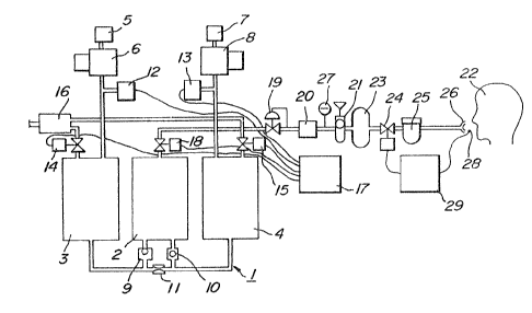
' Throughout different views of the drawings,
1, 61 are oxygen concentrators, 2 is a reservoir tank,
3, 4 are a'bsorption cylinders, 5, 7 are air cleaners,
6, 8 are compressors, 9, 10 are one-way valves~ ll is
an orifice, 12, 13 are pressure switches, 14, 15 are
' solenoid-operated release valves, 16 is a silencer,
' 17 is a controller, 18 is a shutout solenoid valve,
' l9 is a reducing valve, 20 is a bacteria filter, 21 is
a flow meter, 22 is a patient, 23 is a 'buffer tank,
24 is a breath-synchroniæing solenoid valve, 25 is a
humidifier, 26 is a nasal cannula, 27 is an oxygen
analyzer, 28 is a thermocouple, 29 is a gas-supply
regulator, 31, 32 are power source terminals, 33, 34,
'
~ ~ ~~ ~ ~ 3
35 are relays, 41 i.s a ~:lif~erentia:L amplifier, l~2~ ~3,
44 are operational amplifiers~ l~5 is a variable resi.stor,
46 ls a low-pass filter, 47 is an A/D converter, 48 is
an operational control unit, 49 is a central processing
05 unit (CPU), 50 is a timer, 51, 52, 53, 54 are memories,
5~ i5 an outside input means, 56 is an alarm, 57 is a
buzzer, 62 is a five-way solenoid valve, 63 is a sliding
valve, 64, 65 are passages, and 66 is a con-troller
means.
10Referring to Fig. 1 showing a-n embodimen-~ of
the invention, an oxygen concentrator 1 consists of one
reservoir tank 2 and two adsorption cylinders 3 and 4.
The adsorption cylinder 3 i5 com~ec-ted to a compressor 6
with an air cleaner 5, so that after being treated by
the air cleaner 5 for dust removal the air is compressed
by -the compressor 6 and the compressed air is clelivered
to the adsorption cylinder 3. Similarly, the other
adsorption cylinder 4 is connected to a compressor 8
, with an air cl.eaner 7, so that compressed air from the
¦ ~ compressor 8 is delivered to the adsorption cy:Linder L~,
The adsorption cyl:inders 3 and ~ are connec~ed to the
reservoir tank 2 through one way valves 9 and 10 respec-
tivey, and the two cylinders 3 and 4 are also comm~micated
to each other through an orifice 11, so that the oxygen-
enriched gas produced by one adsorption cylinder 3 or 4
is fed to the reservoir tank 2 through the corresponding
one-way valve 9 or 10 while a par-t of such gas i5
directed to the other adsorption cylinder 4 or 3 through
.~
- 15 -
~ 2 ~ 3
the oriEice 11 as purge gas.
Pressure switches 'l2 and 13 are mounted on
the input sicle passages of the a(lsorption cy'linders 3
~nd 4 respectively, wh:ile the input sides of the
oS adsorption cy'linders 3 and 4 a-re also connected to a
common silencer 16 through solenoid-operated release
valves 14 and 15 respectively. The output side of the
silencer 16 is open t:o the atmosphere. A contro'ller 17
is connected to the pressure swic~hes 12, 13 and the
release valves 14, 15. The controller 17 responds to
signals from the pressure switches 12, 13 so as to
control the operations of -the compressors 6, 8, which
are preferably in linear motor type for generating
oxygen-enriched gas therein in an alternate manner.
The controller 17 also controls the release valves 14
and 15, so that substances separated from the adsorbent
in the adsorption cylinders 3 or 4 'by the purge gas are
discharged -to the atmosphere together with the purge
gas through the release valves 14 or 15 and the
silencer 16.
A shutout solenoid valve 18 is mo~nted on the
output side passage of the reservoir tank 2. This valve
18 is closed when the concentrated oxygen s~pplier is
at rest while it is kept open when the supplier is in
operation, so that the oxygen-enriched gas is stored in
the reservoir tank 2 d-uring the rest period of the
: concentrated-oxygen supplier. Whereby, the reservoir
tank 2 is kept ready for immediate operation when the
- 16 -
s~lpplier is restarted ~he pressure of the oxygen-
enriched gas deliverecl through the shutout solenoid
v~lve 18 is reduced to a proper level ~or inhalation
treatment by a reduc:ing valve 19, and the gas is purified
05 by a bacteria filter 20 and its -flow rate is adjusted
at a level suitable for a patient 22 by a flow meter 21
having a needle valve type adjusting mechanism. The gas
is then applied to a buffer tank 23, and a breath-
synchronizing solenoid valve 24 controls the gas stream
from the buffer tank 23 to a patient 22 through a
humidiEier 25 and a nasal cannula 26. The humidifier 25
gives a proper humidity to the oxygen-enriched gas so
as to make it suitable for inhalation treatment of the
~ patient 22.
.. 15 An oxygen analyzer 27 may be provides at a
~r~ suitable position between the shuto-ut solenoid valve 18
i~ and -the breath-synchronizing solenoid valve 24, so as
.~: to facilitate the cletection of any malfunction of the
' oxygen concentrator 1, especially abnormality of the
adsorbent, by operators such as medicaL doctors and
nurses. ln the lllustrated embodiment, the oxygen
. analyzer 27 is provided between the bacteria filter 20
and the flow meter 21 as shown in Fig. 1.
As a sensor to detect the exhalation phase o
., 25 the respiration of the patien-t 22, this embodiment uses
a thermocouple 28 mounted on the nasal cannula 26 in
,~ such a manner that the thermocouple 28 is exposed to
l~ the respiratory air flow through the patient's nostril.
~
- 17 -
'-
~'
~`
,~,
'.''.
2~
rhe o~tp~lt ~rom the therm(>co~lple 2g is applied to a
~as-~upply regulator 29 which controls the operation o~
the breath~synchron:izing solenoid valve 2~ based on the
in~orrnation from the thermocuple 28.
05 Fig. 2 shows a sequential circuit diagram of
the controller 17 of Fig. 1. Each o~ the pressure
switches 12 and 13 has three terminals; namely~ a
common contact COM connected to a fixed end of a swingable
blade 12a or 13a, and two terminals H and I. with which
the free end of the swingable ~lade 12a or 13a selectively
comes in contac-t. In the illustrated embodiment, when
the pressure in the corresponding adsorption cylinder 3
(4) is equal to or higher -than a predetermined value,
the swingable blade 12a (13a) is kept in contact with
the terminal H, while the swingable blade 12a (13a) is
kept in contact with the terminal L as long as the
above pressure is below the above precletermined value.
The terminal COM of the pressure switch 12 is con-nected
to one power source terminal 31 while the terminal COM
;20 of the pressure switch 13 is connected to another power
source terminal 32. The power source terminals 31
and 32 are connected to a S~li table control power source
(not shown).
; A relay 33 is provided between the terminal H
of the pressure switch 12 and the terminal L of the
other pressure switch 13. The relay 33 has two normally
open relay contacts 33-1 and 33-3 and one normally
closed relay contact 33-2. The normally open relay
- 18 -
~ 2~ ~
contact 33-1 is connected between the relay 33 and the
power source terminal 3l as a se'lf-hold contact for the
re`Lay 33. The normally closed relay contact 33-2 is
serially connected to a relay 34, and the serial circwit
05 of the re'lay contact 33-2 and the relay 34 is connected
across the power source terminals 31 and 32~ The normall.y
open relay contact 33-3 is serially connected to a
relay 35, and the serial circuit of the relay contact
33-3 and the relay 35 is also connected across the
lo power source terminals 31 and 32.
The relay 34 has a normal.ly open relay contact
34-1, which contact is connected be-tween one power
source terminal 31 ancl one joint of a parallel combination
., of the compressor 6 and the solenoid-operated release
valve 15, the parallel combination having its o-pposite
joint connected to the other power source terminal 32.
The relay 35 has a normally open relay con-~act 35-1,
', which contact is connected between one power source
terminal 31 and one joint of a parallel combination of
"~ 20 the compressor 8 and the solenoid-operated -release
:. valve 14, t'he parallel combination havi.ng its opposite
jo:int connected to the other power source terminal 32.
Fig. 3 shows the elec-tric circuit of the
gas-supply regulator 2~ of Fig. 1. The outpu-t from the
thermocouple 28 acting as a sensor of respiration is
', applied to a differen-tial amplifier 41 of the regulator
: 29. Operational amplifiers 42 and 43 of the differentia'l
`,, amplifier 41 amplify the input from the thermocouple '~8
." - 19 -
"~ .
:,
:,
"',
'
.,
~ 3
ancl apply their output t.o an output stage operational
amplif:ier 4~l having a v~riable resistor 45 for g~in
adjustment. The ou~put f-rom the operational. ampl:ifier 44
is applied to a low-pass :Eilter 46 for eliminating
05 high-frequency noise and then converted int~ digita~L
signals by an A/D converter 47, which digital signals
are applied to an operational control unit 48.
The control unit 48 has a central processing unit
(CPU) 49, a timer 50, and memori.es 51 through 54.
The CPU 49 is connected to an outside input means 55,
such as a keyboard, through which means a ratio between
the duration of an inhalation phase and the length of a
specific end portion thereof is applied to the CPU 49
as an input information.
Prefera'bly, the gas-supply regul.ator 29 has a
fool-proof mechanism; namely, the above-mentioned ratio
~, of a desired magnitude can be accepted only when it
. falls wlthin a certain predetermined range, lest a wild
.. input at the outside input means 55 by a mistake should
~' 20 cause a tota'l stop of the oxygen-enriched gas supply.
The timer 50 has three functions; natnely, a
function ot' applying interruption signals to the CPU 49
for sampling the outp-ut from the A/D converter 47 at
certain intervals, e.g,, at every 10 msec in the
; 25 illustrated embodiment, a function of measuring the
open time of the breath-synchronizing solenoid valve 24
in the inhalation phase, and a func-tion of measuring the
duration of individual inhalation phases and exhalation
- 20 -
-'
phases. The memory 51 stores the data of preceding
samp:ling, wh-ich sasnpl:ing is ef:fected in succession in a
cyc:L-ic manner by the CPU l~g The memory 52 stores
flags Eor identifying the inhalation phase and the
05 exhalation phase, e.g., a bit "l" for the inhalation
phase and a bit "0" for the exhalation phase as in the
case of the illustra-ted embodiment. The memory 53
stores time data on inhalation phases of the immediately
preceding six normal respiratory motions while updating
them. The memory 54 stores a program for controlling
the operational control unit 48.
The CPU 49 of the illustrated embodiment
carries out the operations as instructed by the program
from the memory 54 based on -the data from the A/D
~, 15 converter 47, the time data on the past six normal
inhalation phases as stored in the memory 53, and the
data from the outside input means 55, so that control
~1
, signals for the brea-th-synchronizing solenoid valve 24
are dispatched from the CPU 49 as a result of such
~ 20 operations. When an alarm 56 for indicating irregularity
: of the patient's respiration and a buzzer 57 for indicat-
ing the normal operation of the concentrated-o~ygen
supplier are provided, the CPU 49 also controls the
, operations of such alarm 56 and the buzzer 57.
: 25 The operation will be described now.
The operation of the oxygen concentrator 1 will be
explained at first by referring to Fig. l and Fig. 2.
When the concen~rator 1 is star-ted withou~ high pressure
- 21 -
,
.
,~,
`:,
~q~jzzlr~3
in the a(lsorption cylinders 3 an(l ~ the swingab'le
b'lades 12a and ]3a of the pressure switches 12 and 13
are kept on their L contacts, so that the re'Lay 3l~ is
energized. Accordingly, the normally open re:Lay contact
05 34-1 is closed, and the compressor 6 is started ancl the
solenoid-operated release valve 15 is actuated so as to
open the passage from the adsorption cylinder 4 to the
atmosphere through the silencer 16. Thus, the air
purified by the air cleaner 5 and compressed by the
lO compressor 6 is delivered into the adsorption cylinder 3,
and nitrogen in the air thus delivered ls adsor'bed by
the adsorbent filled in the cylinder 3 so as to increase
the oxygen concentration o~ the air, and the oxygen-
enriched gas from the c,ylinder 3 is stored in the
15 reservoir tank 2 through the one-way valve 9.
At the same time, a part of the oxygen-enriched
gas is delivered to the other adsorption cylinder 4
through the orifice 11 as the purge gas, so that nitrogen
and moisture carried 'by the adsorbent in the cylinder 4
20 are released by the purge gas and clischarged to the
atrnosphere through the now open release va'lve :L5 and
" the silencer 16. W~lereby, the abi'lity of the adsor'bent
in the cylinder 4 is regenerated and revived.
In response to the operation of the compressor
, 25 6, the inside pressure of the adsorption cylinder 3
,' increases. When that inside pressure reaches a cer-tain
value, the swinga'ble blade 12a of the pressure switch 12
is -turned to the terminal H, 50 -that the relay 33 is
~` - 22 -
~q~ q~
ellergize(l. Accordingly its norrnally open relay contact
33-1 is closed to complete the self-hold circuit oE the
relay 33, and the energization of the re:Lay 33 is
maintained by its own relay contact 33-1 everl when the
05 inside pressure of the adsorption cylinder 3 decreases
and the swingable blacle 12a of the pressure switch 12
is turned to the terminal L. Upon energization of the
relay 33, its normally closed relay contact 33-2 is
opened and its normally open relay contact 33-3 is
closed, so that the relay 34 is de energized and the
relay 35 is energized. The de-energi~ation of the
relay 34 causes the relay contact 34-1 to open~ and the
compressor 6 comes to res-t and the solenoid-operated
release valve 15 is -turned off and closed.
` 15 On the other hand, when the relay 35 is
energized, its normally open relay contact 35-1 is
closed, so as to start ~he compressor 8 and turn on the
. solenoid-operated release valve 14 for opening the
- passage from the adsorption cylinder 3 to the silencer 16.
Thus, the gas in the adsorption cy].inder 3 can be
discharged to the atmosphere through the release
valve 14 and the silencer 16, so as to facilitate the
desorption of nitrogen and moisture adsorbed in the
adsorbent in the cylinder 3. After the compressor 8 is
started, the air cleansed by the air cleaner 7 and
, compressed by the compressor 8 is delivered through the
adsorption cylinder 4 to the reservoir tank 2 as the
oxygen-enriched gas through the one-way valve 10.
; - 23 -
.,
",
'~'
~ 2 ~ v3
A part of the oxygen-enrich~cl gas ~from the cylinder
is a-Lso appliecl to the other cylincler 3 th-rough the
orifice lL as the pllrge gas, so as to regenerate an~3
reactivate the adsorbent in the cylinder 3 in the
05 manner descri'bed above.
When the inside pressure of the aclsorption
cylinder 4 increases and reaches a certain value, the
swingable blade 13a of the pressure switch 13 mounte~l
on the input side of the adsorption cylinder 4 is
turned ~o its terminal H, so as to de-energized -the
relay 33 in the circuit of Fig. 2. Hence, the relay 35
is de-energized and the relay 34 is energized again.
Thus, the conditions of the control circuit of Fig. 2
come back to -that at the beginning of the operation of
the oxygen concentrator 1, and one cycle of the alternat-
ing operations of the adsorption cylinders 3 and 4 is
completed. Thereafter, the above-descri'bed opera-tion
will be re-peated in a cyclic manner, and the oxygen-
enriched gas will be stored :in the reservoir tank 2.
It is noted here that the oxygen concentrator 1
of the illustrated embodiment i5 adapted to ensure
quick bwildup of a sufficiently high oxygen concentration
upon its s-tart even if its preceding operation is ceased
at an arbitrary time. More particularly, the actual
control circuit of the oxygen concentrator l is such that
even after the turning off of its start-stop swi-tch,
the above-descri'bed operation including the supply of
the purge gas is main~ained wntil the regeneration of
- 24 -
''
23
the aclsorbents in both of the adsorption cylinders 3
and 4 is comp'!eted, and upon completion of such -regenera-
tion, the operation is automGItically brought to rest.
Besides, in order to prevent the deterioration of the
05 adsorbent due to its contact with the moisture of the
open air when the oxygen concentrator l is not used,
the adsorption cylinders 3 and 4 and the associated
pipings i,n the em'bodiment of Fig. 1 are airtightly
sealed rom the open air when the concentrator 1 is not
used for any extended period of time.
The operation of the gas-supply regulator 29
will be described now. Fig. 4A shows the waveform of
the output voltage from the thermoco-uple 28 as seen at
the input side of the A/D converter 47 after the
lS amplification at the differential amplifier 41 and the
noise elimination at -the low-pass filter 46. Since the
' thermocouple 28 is exposed to the respiratory air
,' passing the patient's nostril, its output voltage
' gradually increases during the exhalation phase in
which the air is exhaled from the inside of the patien-t's
body whiLe its output gradually decreases during the
inhala~ion phase. Thus, the output vo'ltage of the
therrnocowple 28 is approximately sinusoidal.
~, The A/D converter 47 converts the output of
the thermocoupl 28 into digital signals in the following
manner. The CPU 49 samples the voltage of Fig. 4A at a
regular interval of 10 msec in response to the inter-
ruption signal from t'he timer 50 and the sampled value
- 25 -
:,
~ ~ 6~
is s~:orecl in the memory 51 as a temperature datulrl, and
th~ CPlJ l~9 compares the latest temperature as sampled
a~ainst the preceding temperature datulD retrie~ed from
the me~ory 51. If the Latest temperature as sampled is
05 higher than the preceding temperature clatum, the respira-
tion is in the exhalation phase wherein -the output
voltage of the thermocouple ~8 gradually increases as
shown ln Fig. 4A. On the other hand, if the latest
temperature as sampled is lower than the preceding
lQ temperature datum, the respiration is in the inhalation
phase wherein the output voltage of the thermocowple 28
gradwally decreases as also shown in Fig. 4A. To identify
the durations of the exhalation and inhalation phases,
a binary flag "11' for exhalation and a binary flag "0"
for inhalation are stored in -the memory 52 dwring -the
respective phases.
Let it be assumed that, at a certain instant,
the memory 52 carries a binary flag "1" indicating that
the respiration is in the exhalation phase. During the
exhalation phase, the temperature dat-um stored itl the
memory 51 is renewed by the latest samplecl temperatwre
only when such latest temperature as sampled from the
A/D converter 47 is higher than the preceding temperature
dat-um retrieved from the memory 51. If the latest
temperature as sampled is lower than the preceding
temperature datum retrieved from the memory 51, i.e.,
at the transit from the exhalation phase to the inhalation
phase, the binary 1ag in the memory 52 is changed to "0"
- 26 -
~ 2'~ ~
and thc latest lower ternperature as sampled is stored
in the memo-ry 51 as a new datum. A~ the same time, the
breath-syrlchronizing solenoid valve 24 is turned on for
opening the passage to the nasal cann~la 26, an(l the
05 sw~ply of oxygen-enriched gas to the patient 22 starts
while the buzzer 57 starts to sound. Thereafter, during
the inhalation phase, as long as the newly sampled
temperature is lower than the preceding temperature datum,
such newly sampled -temperature is stored in the memory 51
for renewing the temperatwre datum therein.
Both the duration of the inhalation phase
from the exhalation-inhalation transit to the inhalation-
exhalation transit and the dwration of the exhalation
phase from the inhalation exhalation transit to the
exhalation-inhalation transit are measured by a combina-
tion of the CPU 49 and the timer 50. Whether each of
the thus measured durations falls in a normal range or
~ not is checked by a program stored ln the memory 54.
,, In the illustrated embodiment, the normal range of the
duration of both the inhalation and exhalation phases
is assumed to be 1-15 seconds. When clurat:ions of the
~' inhalation and exhalation phases are normal~ lata on
the immediately preceding six consecwtive sound inhalation
; durations are stored in the memory 53 while renewing
them in sWccession~
On the other hand, if any of the inhalation
durations and exhalation dura-tions falls outside the
above normal range~ it is ass-umed that abnormality of
- 27 -
'~'
''
'~:
~ X 3
a kind h~s occurreci on the side of the patient 22 or
the ~hermoco~ple 28. Such abnormality is inEorMed to
doctors ~nd nurses by actuating the alarrn 56 by the
CPU 49. At the same time, the breath-synchroniz:ing
05 solenoid valve 24 is controlled in such a manner that
the oxygen-enriched gas is continuously supplied to the
pa-tient 22. The renewal o-f the data on the preceding
six consecutive sound inhalation durations is effected
when a new inhalation duration datum of the latest
0 sound respiratory cycle is made available by erasing
the oldest (seven respiratory cycles be:Eore) datum and
storing such new inhalation duratlon datum.
When the respiratory cycles are sound, the
oxygen-enriched gas is supplied only in the inhalation
phase. The duration of such supp:Ly, namely, the cluration
of the opening of the breath-synchroni~ing solenoid
valve 24 (to be referred -to as the "valve open time"~,
is co-ntrolled by a combination of a time ratio set on
the outside input means 55 and the average of the
preceding six consecutive sound inhalation durations.
iMore particularly, at the tran~it Erom the exhalation
phase to the inhalation phase, data on the immediately
preceding six consecutive sound inhalation dura-tions
are read from the memory 53 for determining the average
value thereof. A product of that average value of the
inhalation d-urations and the -time ratio set on the
outside inpu-t means 55 is calculated. The valve open
;: time is determined by subtracting the above produc-t
~ - 28 -
~,
''
trom the above averaKe value o:f the s:ix inhalation
durations.
That valve open ti.me is set on the timer 50,
and as the oxygen-enriched gas is supplie~ it is co-unted
05 down, so that when the thus set time is reduced to zero
by the counti.ng down the breath-synchronizing solenoid
valve 24 is c:Losed. Thws, the val.ve open tirne for the
breath-synchronizing solenoid val.ve 2ll for a specific
inhalation phase is shorter than the average value of
the immediately preceding six consecutive inhalation
durations by the time rat.io set on the outside input
means 55, as shown in Fig. 4B. The gas to be filled in
the trachea or other dead space of the patient 22 i.s
provided by the atmospheric air inhaled by him during
the time corresponding to the above time ra-tio.
If the actual duration of an inhalation phase
is shorter than the valve open -time set on the timer 50
for that inhalation phase, the CPU detects the transit
from the inhalation to exhalation based on the temperature
data during the above counting down at the timer 50,
and the flag :in the memory 52 is changed from "0" to
"l". Thus, in this case the breath-synchronizing
solenoid valve 24 is closed before the valve open time
is counted to zero at the timer 50.
Fig. 5 shows a flow chart of the operation of
the CPU 4g in response to the interruption signals from
the timer 50 at lO msec interval.s. The operation of
the CPU will be summarized now. Whe.n th~ operation of
r~` ~ 2 9
~q~ $ ~ ~ ~ 3
the gas-swpp'1,y regu:Lator 29 is started, the temperature
variation of the respiratory air o-f the patient or the
llke 1iving body is rnonitored as a pa-t~ern. In this
embodiment~ the breath-synchronizing solenoid valve ~4
05 is kept open at first unit six consecutive sound lnhala-
tion duration data are stored in the memory 53, so that
the oxygen-enriched gas is continuously supplied to the
patient~s respiratory organ durin~ such initial period.
In each inhalation phase after data on the six consecutive
10 sound inhalation durations are s-tored in the memory 53,
the valve open time for that inhalation phase is
determined based on the average of the -thus stored data
in the memory 53 and -the time ratio set on the outside
input means 55, and the breath-synchronizing solenoid
' 15 valve 24 is turned on from the start of that inhalation
phase for the period of the thus determined valve open
time so as to supply the oxygen-enriched gas to the
respiratory organ of the patient 22 or the like livin~
body.
As long as the souncl respiratory pattern is
maintained J the inhalation duration data older than six
respiratory cycles before the present instant are
erased from the memory 53, so as to ensure the derivation
of the average of the latest six consecutive sound
~ 25 inhalation durations. When the duration of inhalation
;, or exhalation phase falls outside of a normal duration
,' range ~to be separately set), the breath-synchronizing
'' solenoid valve 24 is immediately turned on so as to
. .
" - 30 -
;"
continuously supply the oxygen-enr:iched g~s to the
pat-ient or the like, and at the same time the alarm 56
is actuated. When the sound resp-irat-ion is resumed
thereaEter and conditions for normal operation are met,
05 the breath-synchronized operation is resumed and the
alarm 56 is turned ofE. However, unless the sownd
respiration is resumed, the continuous supply o the
' oxygen-enriched gas is main~,ained and the alarm 56 is
; continuously actuated.
In the above example, the valve open time of
the breath-synchronizing solenoid valve 24 is determined
based on the preceding six consecutive inhalation
durations. However, the invention is not res-tricted to
such preceding six inhalation durations, and an average
of an arbitrary number of the preceding inhalation
durations can be used for determining the valve open
time. As another modiEication, t'he valve open time may
, be determined by taking a product of the duration o-f
the immediately preceding inhalation phase and the time
ratio set on the outslde input means 55 and by su'btracti~K
such product from the duratio-n of the immediately
preceding inhalation p'hase. F-urther, the valve open
time for a following inhalation phase may be determined
, by taking -the average of such a calculated time determined
based on the immediately preceding inhalation dwration
and more preceding valve open times. That is, the
valve open time for the next inhalation phase is
determined by an average of the preceding valve open
- 31 -
~;
'~
time ancl the present inhalation d~lrat:ion 50 IneaSWredminus a product of it and the ratio set on the outside
input means.
Fig~ 6 shows another embodiment of the oxygen
05 concentrator to be used in the concentrated-oxygen
; supplier of the invention. The oxygen concentrator 61
of this embodiment wses one compressor 6 which is
alternately connected to two adsorption cylinders 3 and
4 through a five-way solenoid valve 62. The formation
of the oxygen concentrator 61 is similar to ~hat of the
oxygen concentrator 1 of Fig. 1 except the above five-way
solenoid valve 62 and the use of only one compressor 6.
Like parts are designated by like numerals. The five-way
solenoid valve 62 has a sliding valve 63 which can
selectively assume a first position as shown in Fig. 6
and a second position to the left thereof. At the
first position, the valve 63 connects the compressor 6
to the adsorption cylinder 3 through a passage 64 while
connecting the adsorption cylinder 4 to the silencer 16
through another passage 65. The valve 63 locatecl at
the second position connects the cvmpressor 6 to the
adsorption cylinder 4 through the passage 65 while
connecting the adsorption cylinder 3 to ~he silencer 16
. through the passage 64.
A controller means 66 shifts the valve 63
between the first position and the second position in
response to the ou-tput from the pressure switch 12.
More particularly, when the compressor 6 operates with
.,
~ 32 -
',
,,
~"
,.. .
~: .
, .
: ,
the valve 63 aL the posit:ion 1 as shown in Flg. 6, the
air cleansed by the ai r cleaner 5 and compressed by the
compre~sor 6 enters the adsorption cylinder 3 through
the passage 64, so as to produce oxygen-enriched gas.
05 As in the case of Fig. 1, the ~hus produced oxygen-
enriched gas is stored in the reservoir tank 2 throug'h
the one-way valve 9, and at the same time a part o the
oxygen-enriched gas is delivered to the other adsorption
cylinder 4 through the orifice 11 as purge gas.
The purge gas causes desorption o nitrogen and moisture
from the adsorbent in the adsorption cylinder 4, and
the desorption products are discharged to the atmosphere
together with the purge gas through the passage 65 and
, the silencer 16.
, 15 When the inside pressure of the adsorption
cylinder 3 increases and reaches a certain predetermined
~', value, the pressure switch 12 generates and transmits
such a signal to the controller means 66 that ~he
sliding valve 63 is shifted Erom the position 1 to the
2~ left as seen in Fig. 6 until reaching its second position.
- Whereby, t'he gas in the adsorption cylinder 3 is
dischargecl to the atmosphere together with desor'bed
nitrogen and moisture through the passage 64 and the
sil,encer 16. At the same ti.me, the air cleansed by the
air cleaner 5 and compressed by the compressor 6 enters
the adsorption cylinder 4 through the passage 65 for
' producing the oxygen-enriched gas. The thus produced
,' oxygen-enriched gas is stored in the reservoir tank 2
,,
- 33 -
,
tt~rougtl t:he one-way va~ve :10 "~hi1e a part of the oxygen-
enriche(l gas is cle'livered to the adsorption cyl-inder 3
th~-ough the orifice 1l as the purge gas for efEecting the
regeneration and reactivat:ion oE the adsorbent therein.
05 Therea'ter, when the inside pressure of the
aclsorption cylinder ~l increases and reaches the above-
mentioned certain predetermined value, the controller
means 66 shifts the valve 63 of the -Eive-way valve 62
to the first position as shown in Fig. 6. Whereby, the
oxygen concentrator comes back to the initial condition
and one cycle of the operation of the oxygen concentrator
of Fig. 6 is comple-ted.
Accordingly, when the five-way valve 62 is
used, one compressor 6 can alternately pressuri~e and
purge the -two adsorption cylinders as in the case of
Fig. l using two compressors. It should be noted that
the oxygen concentrator to be used in the concentrated-
oxygen supplier of the invention is not restricted to
the above adsorption type, but membrane type oxygen
concentrator can be also used in the present invention.
As descri'bed in the Eoregoing, the breath-
' sync'hronized concentrated-oxygen supplier of t'he invention
uses a comblnation of an oxygen concentrator, a buffer
tank, a breath-synchronizing solenoid valve, and a
gas-supply regulator which limits the opening time of
the above solenoid valve only to a period available for
useful usage of the oxygen gas, so that the following
outstanding effects can be achieved.
, - 34 -
,~
, .
, .
(a) Table 2 shows the resu~1.t o:f tests on t'he change of
oxygen concentrat:ion of the oxygen-enriched gas in
breathing apparatuses for two cases both wsing the
same ac{sorption type oxygen concentrator; namely,
a case of the breath~synchronized type of the
invention and anot'her case of a conventional
continuous type.
Table 2 Oxygen Concentration
and Supply Method
- r xygen Concentration (%)
Flow Rate Conti uous yAGby~n-~ed
. l 9~ 94
2 90 94
3 76 90
4 58 86
:; _
As can be seen from Tab'Le 2, the `breath-synchronized
type supply according to the invention, which
supplies the oxygen gas only during the inhalation
phase, improves the p~rformance and inhalation
efficiency of -the supplier to a great extend in
comparison with the conven-tional continuous supply
type. If breathing apparatuses of the 'breath~
synchronized supply type and the continuous supply
.
, - 35 -
.
~.
~ype are macle to obtain the sallle inhalation
eEficienc~ by using the same oxygen concentrator~
the breath-synchronized supply type can be made
much smaller in size, lighter in weight, an~ more
oS energy saving ~han t'he continuous s-upply type.
Accorclingly, the concent:rated-oxygen supplier of
the invention makes an epoch-making progress in
the art and makes the oxygen inhalation treatment
at home more readily available.
(b) A buffer tank is provided upstream of the 'breath-
synchroni~ing solenoid valve, so that the pressure
in the ~uEfer tank is raised during the exhalation
~I phase wherein -the supply of oxygen-enriched gas is
''` halted, as shown in Fig. 7A. The discharge of
.,, 15 such raised pressure at the beginning of the
~ inhalation phase resu'lts in a suf~iciently high
,
~:~, peak-like inltial flow rate of the oxygen-enriched
~l gas which is superposed on the steady flow rate in
" each inhalation phase, a9 shown in Fig. 7B. Such
. 20 pea'k-like initial high flow rate matches the steep
,~ ch~nge in the respiratory flow curve from the end
of exhalation phase to the very beg-Lnning of the
inhalation phase in the respiration of the living
~' body, as shown in Fig. 7C. Thus~ the superposition
.', 25 o ~he above initial peak of the oxygen f^low rate
suits the resplratory pattern o the living body
:
very well.
~ Oxygen inhalation efficiency in the living body
.,, - 3~ -
,~'
,i
''.'''
,j
,. .
. .,
~VZ,2~
wa5 testecl wi.th Eour mode`ls of i.nha:lation; name:l.y,
a rllodel. (1) with inhala~ion of a-i-r, a rnodel ~2)
with a continuo~ls supply o:E oxygen-enriched gas at
2 Q/min Erom an oxygen concent-rator, a moclel (3)
wi~h a supply of oxygen-enr-.ic-hed gas at 2 ~/min
only for inhal.atlon phases from an oxygen concen-
trator through a three-way valve which discharged
the oxygen-enriched gas to the atmosphere dur:ing
; exhalation phases, and a model (~) with a supply
of oxygen-enriched gas at 2 Q/min only for inhalation
phases from an oxygen concentrator through a
two-way valve which stored the oxygen-enriched gas
in a buf-fer tank during exhalation phases.
; The result is shown in Table 3.
Table 3 Transcutaneous Tissue Oxygen Partial
Pressure in Living Body for
~ifferent Inhaling Models
_. Transcutaneous Tissue 2
i Mocldel Partial Pressure (tcPO2)
.. (mmHg)
,. _ _ _
. (1) 73.1 + S.~
i (2) 122.7 + 10.5
(3) 105 5 + 15.3
(4) 163.1 + 12.6
',
Similarly, oxygen inhalation efficiency in the
living body was tested for different 10w rates of
inhaling oxygen gas under different gas supplying
- 37 -
;', .
~ 3
conditions; namely, condit.ion (:i) under cont:inuous
oxygen gas supply7 cond:ition (i:i) under interrnittent
oxygen gas supp'ly with a 100 m~ 'buffer t:arlk9
conclition (iii) wnder intermittent oxygen gas
supply with a 200 mQ huffer tank, and condition
(iv) under intermit-tent oxy~en gas supply with a
400 mQ buffer tank. The result is shown in Table 4.
Table 4 Transcutaneous Oxygen Partial Pressure in
Living Body for Di-fferent Gas Supply Rates
Transcutaneous Tissue 2 Par-tial
Pressure (tcPO2) (mmHg)
Supply Oxygen ~low Rate (Q/min)
Condi- l _ ~
tions 0 5 i 1.0 _ 2.0 3.0
(i) ~9.9~3 4 93.1+~.5 129.7~13.9 145.2+5.8
(i.i) 101.3+~.6 lOg.7*6.5 173.~+18.1 193.9~17.5
(i:ii) 101.8+3.5 112.5+12.3 175.2+18.6 lgl.7~15.6
(iv) 10~.6+3.1 108.4+4.0 173.1~12.2 19~ 0.8
As can be seen from the test results of Table 3 and
Ta'ble 4, with the intermittent supply of oxygen,
the oxygen-enriched gas can 'be inhaled at a very
high efficiency. Especially, the model (4) o-f
Table 3 shows -that the use of the buffer tank, the
capacity of which as small as 100 mQ is shown to be
effective enough in Table 4, improves the effective-
ness of the breath-synchronized concentrated-oxygen
- 38 -
.
t~
supply system to a greater extent.
(c) Since the duration of the suppLy of the oxygen-
enrichecl gas for each inha:Lation phase ls controlled
by a combination oE the preceding inhala~ion
05 durations and the time ratio of a specific end
portion of the inhalation duration as set through
an outside input means, the oxygen-enriched gas
can be supplied in excellent synchronism with the
re~piration of the patient or -the like, so that
the efficiency of the oxygel1 gas supply can be
further improved. In view of the high inhalation
efficiency thanks -to -the use of the buffer tank,
the time ratio indicating the length of the specific
end portion oE the inhalation duration, in which
end portion the gas supply is in-terrupted, can be
made comparatively large.
Thus 3 the invention facilitates fwrther miniatura-
tion, weight reduction and energy saving in the
oxygen concentrator.
(d) The oxygen concentrator in the illu5 trated embodiment
of the invention wses two adsorption cylinders
which are operated alternately in such a manner
that a part of the oxygen-enriched gas prod-uced by
one adsorption cylinder and saved by closing the
breath-synchronizing valve is delivered -to -the
other adsorption cylinder as purge gas, so -that
the oxygen concentrator can operate at a fairly
high flow rate of the oxygen-enriched gas without
- 3~ -
re(l~lcing the oxygen concentration therein.
Accordingly, the performance oE such oxygen concen
trator can be considerably improved as co~lpared
with conventional oxygen concentrators. The improved
05 performance facilitates further miniaturation,
weight reduction and energy saving in the oxygen
concentrator.
The interruption of the supply of the oxygen-enriched
gas during exhalation phasès contrihutes to speeding
lo up of the pressure buildup at the adsorption
cylinders and quickening of the switching of the
al.ternate operations of -the adsorption cylinders.
The effect of such quickened switching will be
positively combined with the above-mentioned
effect of the alternate operation of two adsorption
3, cylinders in improving the performance of the
i oxygen concentrator.
! ( f ) The thermocouple used in the above emb~d-lment Eor
sensing the pat:ient's resp:iration produces signals
which accurate:ly follow the respiration and
facil:itates accurate control. The thermocouple as
; the respira-tion sensor can be made small and light
so as to eliminate the resistance to respiration
and to reduce the patient's uneasy feeling~ and
such sensor with stable performance can be
manufact-ured at a low cost on a mass production
..
basis. In fact, it may be discarded after each
inhalation treatment.
, .
; ~o-
,
'',
'~2 ~ 3
(g) The buzzer used in the above embodiment sounds in
sync'tlronism with the operation of the breath-
s~nchroniz-ing solenoid valve, 50 as to in~orm the
patient of the orcle-rly operation oE the breathlng
05 apparatus. Whereby, the patient becomes confident
with the relia'ble operation of the apparatus.
Besides, such buzzer can be used for training the
patient in 'Learning a proper respi-ratory rhythm
suitable to him, which training is useEul in
rehabilitation from chronic respiratory ailment.
(h) When a membrane type oxygen concentrator is used,
the service life of the selectively permeable
membrane therein can be improved by minimizing the
oxygen production through suppression of wasteful ,
use of oxygen.
Although the invention has been described
with a certain degree of particularity, it is understood
that the present disclosure has been made only 'by way
of example and that numerous changes in detai'Ls of
construction and the combination and arrangement of
parts may be resortecl to without depart:ing from the
scope of the invention as hereinafter claimed.
;
:
- 41 -
~,